Note: Descriptions are shown in the official language in which they were submitted.
CA 02487568 2004-11-12
-1-
TITLE OF THE INVENTION
CONNECTOR ASSEMBLY
FILED OF THE INVENTION
The present invention relates to a connector assembly. In particular the
present
invention relates to a connector assembly for interconnecting a cable
comprised of a series of insulated conductors with the bifurcated connectors
of
a connector block.
BACKGROUND OF THE INVENTION
A variety of prior art systems exist for terminating the ubiquitous twisted
pair
cables used in telecommunication systems with a connector suitable for
insertion to a connector block comprised of a series of Insulation
Displacement
Connectors (IDCs). These prior art systems typically provide, within the
connector housing, a means for retaining the cables within the housing, for
example by means of collars or the like which, during assembly, encircle the
cable thereby hindering its retraction from the connector housing.
Additionally,
to simplify the assembly of such connectors in the field, the connectors,
which
are typically of two part construction, typically comprise a series of
bifurcated
IDC connectors arranged in one side of the connector housing into which the
ends of the twisted pairs of conductors can be inserted using a suitable tool.
As
is known in the art, such IDC connectors slice through the insulating covering
of
the individual conductors, thereby bringing the conductor into contact with
the
IDC connector. The IDC connectors are in turn connected to, or form part of, a
terminal which is exposed along a front face of the connector, the terminals
adapted for insertion into the connector block.
CA 02487568 2004-11-12
-2-
There are also disclosed prior art connectors which provide posts or the like
around which the conductors can be arranged thereby improving to some
degree the performance of the cable/connector as well as the strength of the
assembled cable/connector.
However, the above discussed prior art devices typically untwist a relatively
large amount of conductor from each twisted pair in order to align the
conductor
with and insert it into the provided IDC connector. Additionally, no effort is
made in such prior art conductors to ensure that the point of contact between
twisted pairs emerging from the exposed end of the cable, at least two of
which
must typically be crossed in order to be attached in the correct sequence with
the IDC connectors, is minimised. Furthermore, the point of insertion of the
individual conductors into the IDC connectors is typically arranged along a
parallel line, which may give rise to unwanted cross-talk and the like thereby
reducing performance of the connectors, especially at high frequencies.
As a result, the above discussed prior art devices are typically unsuitable
for
use in connectors which must meet the Category 6 performance standards.
SUMMARY OF THE INVENTION
To address the above and other drawbacks of the prior art, there is disclosed
a
connector assembly for interconnecting an end of a cable comprising one or
more twisted pair conductors, each of the conductors enveloped in an
insulating covering, with the bifurcated contacts of a connecting block. The
assembly comprises an insulated housing and a. plurality of non-contacting
conductive terminals disposed in the housing. Each of the terminals comprises
a blade exposed along a front face of the housing and adapted to be inserted
into one of the bifurcated contacts, and a piercing mechanism comprising at
least one tooth. Each of the conductors is terminated by one of the terminals,
CA 02487568 2004-11-12
-3-
the teeth puncturing the insulated covering of a free end of the conductor
thereby bringing the terminal into conductive contact with the conductor.
There is also disclosed a conductive terminal for terminating a conductor
enveloped in an insulated covering and providing interconnection with a
connector block comprising at least one bifurcated contact. The terminal
comprises a contact blade adapted for insertion between the bifurcated contact
and a piercing contact mechanism comprising at least one tooth, the tooth
adapted for puncturing the insulated covering thereby bringing the terminal
into
conductive contact with the conductor.
Additionally, there is disclosed a patchcord for interconnecting a first
connector
block comprising a series of bifurcated connectors with a device. The
patchcord
comprises a cable comprising at least one twisted pair of conductors and a
first
connector assembly adapted for interconnecting a first end of the cable with
the
bifurcated connectors of the first connecting block. The first connector
assembly comprises an insulated housing and a plurality of non-contacting
conductive terminals disposed in the housing. Each of the terminals comprises
a blade exposed along a front face of the housing and adapted to be inserted
into one of the bifurcated contacts and a piercing mechanism comprising at
least one tooth. Each of the conductors is terminated by one of the terminals,
the teeth puncturing the insulated covering of a free end of the conductor
thereby bringing the terminal into conductive contact with the conductor.
Furthermore, there is disclosed a wire guide for interposition between an end
of
a cable, the cable comprised of at least two twisted pairs of conductors, and
a
plurality of connector terminals, at least two of the twisted pairs crossing
between the cable end and the terminals. The wire guide comprises at least
two guideways, wherein each of the twisted pairs is inserted into a respective
one of the guideways, and wherein the guideways guide each of the twisted
CA 02487568 2004-11-12
-4-
pairs such that at a point of intersection the crossing twisted pairs are
maintained substantially at right angles.
There is also disclosed a method for adapting an end of a cable comprised of a
plurality of twisted pairs of conductors, each of the conductors enveloped in
an
insulating covering and having a free end, for interconnection with the
bifurcated conductors of a connecting block. The method comprises the steps
of providing a connector assembly comprising a plurality non-contacting
conductive terminals disposed in an insulated housing, each of the terminals
comprising a blade exposed along a front face of the housing and adapted for
insertion into the bifurcated conductors, and a piercing mechanism having at
least one tooth, inserting the free end of each of the conductors into the
housing, and, for each terminal/conductor pair, puncturing the insulating
covering the free end of each of the conductor with the piercing mechanism
teeth thereby bringing the terminal into conductive contact with the
conductor.
There is furthermore disclosed a method for adapting an end of a cable
comprised of a plurality of twisted pairs of conductors, each of the
conductors
enveloped in an insulating covering and having a free end, for interconnection
with the bifurcated conductors of a connecting block. The method comprises
the steps of providing an insulated housing, providing a plurality of
terminals,
each of the terminals comprised of a blade adapted for insertion into the
bifurcated conductors and a piercing mechanism having at least one tooth, and,
for each free end, arranging the free end within the housing so the free end
is
substantially in parallel to the other free ends and, using one of the
terminals,
puncturing the insulating covering of the free end with the piercing mechanism
teeth thereby interconnecting the terminal with the conductor. Once assembled,
the blades are exposed along a front face of the housing.
There is additionally disclosed an adaptor for interconnecting a cable
CA 021487568 2004-11-12
-5-
terminated with a connector plug comprising a plurality of conductive contacts
with the bifurcated contacts of a connecting block. The adaptor comprises an
insulated housing, a socket moulded in a first surface of the housing, the
socket
adapted to receive the connector plug and comprising a plurality of conductive
elements disposed therein, wherein when the plug is inserted into the socket
the contacts move into electrical contact with the elements, and a plurality
of
non-contacting conductive terminals disposed in the housing, each of the
terminals comprising a blade exposed along a second surface of the housing
and adapted to be inserted into one of the bifurcated contacts. Each of the
terminals is in conductive contact with one of the conductive elements.
There is also disclosed a connector assembly for interconnecting an end of a
cable comprising at least two twisted pair conductors, each of the conductors
enveloped in an insulating covering and having a free end, with the bifurcated
contacts of a connecting block. The assembly comprises an insulated housing
and a plurality of pairs of adjacent non-contacting conductive terminals
disposed in the housing, each of the terminals comprising a blade and a
conductive strip attached substantially at right angles towards one end of the
blade, wherein the blades are exposed along a front face of the housing. Each
of the free ends of a twisted pair of conductors is in conductive contact with
a
second end of the conductive strips of a terminal pair and the conductive
strips
of adjacent terminal pairs are attached towards different ends of the blades.
BRIEF DESCRIPTION OF THE DRAWINGS
Figure 1 is a raised front perspective view of a connector assembly in
accordance with an illustrative embodiment of the present invention;
Figure 2 is an exploded raised rear perspective view of a connector assembly
with the cover removed in accordance with an illustrative embodiment of the
CA 02487568 2004-11-12
-6-
present invention;
Figure 3 is an assembled view of the connector of Figure 2;
Figure 4 is an exploded raised rear perspective view of a terminal housing in
accordance with an illustrative embodiment of the present invention;
Figure 5 is a raised rear perspective view of a terminal in accordance with an
illustrative embodiment of the present invention;
Figure 6 is a raised rear perspective view of a wire guide in accordance with
an
illustrative embodiment of the present invention;
Figure 7 is a raised rear perspective view of an assembled connector assembly
with the insulating cover installed in accordance with an illustrative
embodiment
of the present invention;
Figure 8 is a raised rear perspective view of an assembled connector assembly
with the outer insulating protective housing installed in accordance with an
illustrative embodiment of the present invention;
Figure 9A is a front view of a connector assembly in accordance with an
illustrative embodiment of the present invention;
Figure 9B is a side cut-away view along 9B of the connector assembly in Figure
9A;
Figure 10 is a raised side perspective view of a connector assembly in
accordance with an alternative illustrative embodiment of the present
invention;
CA 02'487568 2004-11-12
-7-
Figure 11 is a raised front perspective view of a BIX connecting block; and
Figure 12 is an adaptor in accordance with an alternative illustrative
embodiment of the present invention.
DETAILED DESCRIPTION OF THE ILLUSTRATIVE EMBODIMENTS
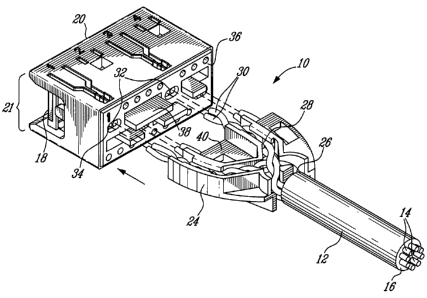
Referring to Figure 1, a connector assembly, generally referred to using the
numeral 10, is disclosed. The connector assembly 10 terminates a cable 12
comprised of a series of twisted pairs of conductors 14 covered in an
insulating
jacket 16 by a series of conductive terminals as in 18 fabricated, for
example,
from a single piece of rigid conducting material such as stamped phosphor
bronze plated with nickel or gold. Each conductor 14 is manufactured, for
example, from a conductive material such as of 23 or 24 gauge solid copper
wire covered with a suitable dielectric insulating cover, although other
gauges
and types of conductors, such as stranded conductors, could be used.
The terminals 18 are retained within an insulated housing 20 and exposed
along a front face 21 thereof, the housing fabricated, for example, from a non-
conductive material such as injection moulded plastic. In the disclosed
illustrative embodiment, the multi-conductor cable 12 comprises four (4)
twisted
pairs of conductors 14 terminated by eight (8) terminals 18, although it will
be
understood that other configurations would be possible, including those with
one, two or three twisted pairs. The housing also illustratively includes an
insulted protective covering 22 providing a gripping surface for removing and
installing the assembly 10 from/to a connector block (not shown).
Referring now to Figure 2, in order to align the twisted pairs of conductors
14
with the correct terminals 18, a wire guide 24 is disposed between the end 26
of the cable jacket 16 and the insulated housing 20. Guideways as in 28,
CA 02487568 2004-11-12
_ $ _
illustratively in the form of channels, in the wire guide 24 separate and
guide
the twisted pairs of conductors 14 and align the free ends as in 30 of the
conductors 14 with a series of pairs as in 32 of conductor accepting apertures
34 moulded in the rearward face 36 of the insulated housing 20.
During assembly, the free end 30 of each conductor 14 is inserted into its
respective conductor accepting aperture as in 34 as the wire guide 24 is
mounted onto the rearward face rearward face 36 of the insulated housing 20.
The spacing between the aperture pair 32 terminating a given twisted pair of
conductors 14 is adapted to be substantially the same as the separation
between the conductors 14 of the twisted pair in their untwisted state.
Additionally, a series of raised bosses 38 mate with corresponding cutaway
portions 40 in the wire guide 24 thereby holding it securely to the insulated
housing 20.
Referring to Figure 3, an insulated housing 20 with a wire guide 24 mounted
thereto is shown.
Referring now to Figure 4 in addition to Figure, 3, once the conductors 14
have
been inserted into the insulated housing 20 via the conductor accepting
apertures 34, the terminals as in 18 are inserted into the insulated housing
20
via corresponding slots as in 42 moulded into the insulated housing 20,
typically using a suitable tool (not shown).
Referring now to Figure 5 in addition to Figure 4, each terminal 18 is
comprised
at one end of a piercing mechanism 44 (illustratively a tri-point mechanism)
comprised of a number of sharp teeth 46. As the terminal 18 is forced into the
slot 42, typically by means of a suitable installation tool (not shown), the
teeth
46 pierce (or are punched-through) the conductor 14, which is held firmly by
an
inner surtace of the aperture 34, perforating the outer insulating cover 48
from
CA 02487568 2004-11-12
_g_
the conductor 14 thereby providing electrical contact between the conductive
core 50 and the terminal 18. Provision of this means of assembly means that
the connector is suitable for assembly by both automated manufacturing means
as well as by a technician in the field. Additionally, the use of the
piercing, or
punch-through, mechanism 44 for interconnecting each terminal 18 with a
conductor 14 ensures that the distance between the individual conductors 14 of
the twisted pairs can be rigorously maintained, thereby improving signal
quality.
Furthermore, the piercing mechanism 44 also ensures that the interconnecting
surfaces between conductor 14 and terminal 18 are minimised, thereby
reducing the deteriorating effect capacitance may have on any transmitted
signals. Also included on each conductive terminal 18 is a securing mechanism
52, illustratively in the form of a serration, which on insertion of the
terminal 18
into one of the slots as in 42, grips the housing 20 thereby retaining the
terminal 18 within the slot 42.
Still referring to Figure 5, the piercing mechanism 44 is connected to a
terminal
blade 54 by a conductive strip 56 which is attached towards one end of the
blade 54. Illustratively, the conductive strip 56 is joined substantially at
right
angles to the blade 54. Referring back to Figure 4 in addition to Figure 5, in
order to provide that the spacing "b" between the piercing mechanisms 44 of
adjacent pairs of terminals 18 is less than the distance "a" between the
blades
54 adjacent of adjacent pairs of terminals 18, a crimp as in 58 is, for
example,
formed in the conductive strips 56.
Still referring back to Figure 4, the terminals 18 are illustratively arranged
in
pairs of terminals wherein the conductive strips 56 of adjacent pairs of
terminals 18 are attached towards opposing ends of the terminal blades 54
(and as a result, when installed arranged towards opposite sides of the
insulated housing 20). In this regard, it is foreseen that the pairs of
terminals as
in 18 are installed via slots as in 42 wherein the slots of adjacent pairs of
CA 02487568 2004-11-12
-10-
terminals as in 18 are accessible through opposite first and second surfaces
of
the housing 20. Once the terminals have been inserted into their respective
slots 42 in the housing 20, the piercing mechanisms 44 of the pairs of
terminals
18 are aligned with the apertures 34 in the rear face 36 of the housing 20. In
order that the piercing mechanisms 44 are correctly aligned with the apertures
34, the pairs of apertures as in 32 are staggered, with alternating aperture
pairs
32 being closer to an opposite side of the housing 20. Arranging the terminals
18 and aperture pairs 32 in this manner permits the integrity of the
performance
of the cable/connector assembly to be maintained. Indeed, in order to transmit
a high performance signal, the quality of the signal is maintained on each
conductor of a given twisted pair due to its unique configuration. Different
characteristics will determine the transmission performance according to the
manner in which the twisted pairs are configured as well as the manner in
which the twisted pairs interact with one another. The configuration of where
and how the conductors are interconnected with the terminals, including the
displacement between adjacent pairs of terminals, is an important aspect. In
this regard, the staggering of the apertures 32 as described hereinabove, and
therefore the point where the conductors 14 of different twisted pairs are
interconnected with the terminals 18, serves to reduce the extent to which
terminals 18 terminating a given twisted pair of conductors 14 interfere with
other pairs of terminals 18, especially those terminal pairs which would
otherwise be adjacent, and therefore in relative proximity.
Referring back to Figure 3, the shape of the guideways 28 is illustratively
selected such that the twisted pairs of conductors 14 terminate opposite their
respective aperture pairs 32. Additionally, the guideways 28 guide the
conductors 14 such that, for those twisted pairs which must necessarily cross
in
order to be aligned with their respective aperture pairs 32, the conductors 14
of
these twisted pairs are held substantially at right angles at their points of
intersection 60. Maintaining the crossing twisted pairs substantially at right
CA 02'487568 2004-11-12
-11-
angles reduces the interference between the crossing twisted pairs, thereby
improving performance of the connector 10 as a whole. Also, as a connector
cable 12 is typically terminated at both ends by the same type of connector
assembly, the various components, including the wire guide 24, may be used
as part of a connector assembly 10 at either end of the cable. Furthermore, a
spacer (not shown), for example in the form of a sheath or shrink tube
surrounding one of the crossing twisted pairs at least at the point of
intersection
60 and illustratively fabricated from a shielding material, can be used to
provide
increased separation (i.e. a gap) between the crossing twisted pairs and
therefore improve performance in terms of mutual interference.
Referring again to Figure 4, by maintaining a short distance between the
rearward face 36 of the insulated housing 20 and the piercing mechanisms 44,
and thereby reducing the length of conductor 14 which must be unravelled from
its twisted pair prior to insertion into the conductor accepting apertures 34,
the
signal performance can also be improved. Indeed, as is known to persons of
ordinary skill in the art, the transmission of high quality high frequency
signals
depends to a large part on each conductor 14 of a twisted pair being
maintained in a particular configuration. Additionally, the crimp 58 formed in
the
terminals 18 allows the distance "b" between the piercing mechanisms 44 of a
pair of terminals 18, and therefore between the ends (reference 30 in Figure
2)
of the individual conductors 14 of each twisted pair to be optimised (for
example, depending on the method of fabrication of the cable 12 which is
terminated by the connector assembly 10) while maintaining the predetermined
or standardised distance "a" between the blades as in 54 of each terminal 18.
For example, in the disclosed illustrative BIX embodiment, a standardised
distance is used for "a" between the blades 54 (which are illustratively
arranged
in parallel, evenly spaced along the front face 21 of the housing 20 and in a
manner such that the blades 54 intersect the front face 21 at right angles) of
0.15 inches. On the other hand, the distance "b" between the piercing
CA 02487568 2004-11-12
-12-
mechanisms 44 of a pair of terminals 18, and therefore the ends (reference 30
in Figure 2) of the twisted pairs of conductors (reference 14 in Figure 2), is
0.04
inches (although this could be varied depending on the type of twisted pair
conductors 14 being terminated by the terminal 18).
Note that, in order to reduce the distance "b" such that it is similar or the
same
to the spacing between the conductors 14 of a given twisted pair, the use of
interconnection mechanisms other than the piercing mechanisms 44, such as
an IDC connection or a soldered interconnection, typically prove unsuitable.
Indeed, both IDC connectors and solder would typically require a much larger
displacement "b" between the terminals of a given pair in order to ensure that
the terminals are not touching. Additionally, both IDC connections and
soldered
connections would typically require a terminal 18 having a much larger surface
area at the point of interconnection as compared to the disclosed piercing
mechanism 44, which, as discussed above, due to the increased capacitive
effects would also have a negative effect on overall performance of the
assembled connector 10.
Referring now to Figure 6, a detailed view of a wire guide 24 having four
guideways 28 for guiding four twisted pairs of conductors (not shown) is
disclosed. Referring to Figure 3 in addition to Figure 6, The wire guide 24
ensures that an appropriate separation is maintained between the twisted pairs
of conductors 14 between the point where the twisted pairs exit the end 26 of
the cable jacket 16 (the guideway inlet as in 62) and where each conductor 14
comes into contact with its respective terminal 18 (the guideway outlet as in
64). In particular, by selecting an appropriate thickness to the substantially
flat
diving layer 66 dividing the upper and lower guideways as in 28 (the "Y"
direction) as well as the relative positions of the inlets 62 into the wire
guide 24
(the "X" direction) inductive interaction between the twisted pairs can be
minimised thus providing for an improved pertormance. Additionally, by varying
CA 02487568 2004-11-12
-13-
length of the wire guide (the "Z" direction) the distance between where the
twisted pairs of conductors 14 exit the end 26 of the cable jacket 16 and the
point at which each conductor 14 is attached to a terminal 18 can also be
optimised. Furthermore, within each guideway 28 a pair of protrusions 68 are
provided for retaining the twisted pair of conductors 14 within the guideway
28
during assembly.
Still referring to Figure 6, the wire guide can illustratively be fabricated
from a
dielectric such as plastic or a shielding material.
Referring now to Figure 3 and Figure 7, once the wire guide 24 is assembled to
the rearward face 36 of the insulated housing 20, the individual conductors 14
of the cable 12 fed through their respective apertures (reference 32 on Figure
2) and the terminals 18 inserted into their respective slots 42, an insulating
material 70 is illustratively moulded over the wire guide 24/conductor 14
assembly. The insulating filler material 70 improves the robustness of the
resulting assembly and is fabricated for example from a non-conducting
material such as plastic. The use of injection moulding, for example, ensures
penetration of the cover material into the guideways (channels) 28 filling
them
completely and thereby binding the conductors 14 within the guideways 28 of
the wire guide 24. This in turn ensures that the positions of the twisted
pairs of
conductors 14 within the wire guide 24 will be strictly maintained, thereby
improving the electrical transmission performance of the connector assembly
10 as well as the resulting mechanical strength of the connector assembly 10.
Referring now to Figure 8, once wire guide 24 has been covered with the
insulating filler material (reference 70 in Figure 7), the insulating
protective
cover 22 is then moulded over the insulating material 70. The insulating
protective cover 22 is manufactured, for example, from a pliable non-
conducting material such as a rubberised plastic or the like. In the surtace
72 of
CA 02487568 2004-11-12
-14-
the cover 22 a series of gripping ridges 74 are formed to provide an improved
grip when the connector assembly 10 is being inserted into or withdrawn from a
connector block. The colour of the material used to form the outer insulating
protective cover 22 may also be varied for a given application. Additionally,
and
in order to improve the mechanical robustness of the connector/cable
interconnection, a reinforcing collar 76 is also moulded between the
protective
cover 22 and the cable jacket 16.
Referring now to Figures 9a and 9b, the assembled connector assembly 10
minimises the distance "d" between the rearward face 36 of the insulated
housing 20 and the point at which contact is made between the terminal 18 and
the conductor 14 via the teeth 46 of the piercing mechanism 44. Additionally,
using the injection moulding technique the twisted pairs of conductors 14 are
encased in the plastic of the insulating material 70.
Provided requisite care is taken during the fabrication of the connector
assembly, the connector assembly 10 as described is sufficient to meet the
performance requirements of Category 6 pursuant to TIA/EIA T-568-B.2-1.
Referring to Figure 10, alternatively the insulating material 70 and outer
insulating protective cover 22 of Figure 7 could be replaced by a suitable
cover
assembly 78 comprised of a first part 80 and a second part 82 which snap fit
together to hold the wire guide and twisted pairs in place.
Referring now to Figures 1, 5 and 11, one or more connector assemblies 10
are designed to mate with a connecting block 84 by inserting the contact
regions (reference 86 on Figure 5) of the terminal blades (reference 54 on
Figure 5) between a series of bifurcated contact slots 88, for example
fabricated from a rigid conducting material such as stamped phosphor bronze
plated with nickel or gold. Illustratively, the contact regions (or forward
edges)
CA 02487568 2004-11-12
-15-
86 of the blades 54 are chamfered in order to facilitate their insertion
between
the bifurcated contact slots 88. As will be understood by persons of ordinary
skill in the art, multiple connector assemblies 10 can be arranged side by
side
on a given connecting block 84. Although the connecting block disclosed is
that
known having the designation BIX, it will be understood by persons of ordinary
skill in the art that a variety of other connecting blocks may also be used,
for
example those known in the art as 110 cross connector blocks or KRONE.
Still referring to Figures 1 and 11, in an alternative embodiment the
connector
assembly 10 and cable 12 of the present invention could assembled with a
second connector assembly 10 mounted on a second end of the cable 12
resulting in a patchcord (not shown) suitable, for example, for
interconnecting
two connector blocks as in 84, or different series of bifurcated contact slots
as
in 88 on the same connector block 84. Additionally, a connector assembly as in
10 could be assembled to the first end of a cable 12 with a device mounted on
the second end of the cable 12, for example an RJ-45 plug or the like,
providing
a patchcord allowing a connector block 84 to be interconnected with a standard
RJ-45 socket or the like. Alternatively, a device such as an electronic
testing
apparatus could be attached directly to the second end of the cable 12. Also,
the conductors 14 at the second end of the cable 12 could be exposed and
inserted directly into the bifurcated contact slots 86 of a connector block
84.
In an alternative illustrative embodiment of the present invention, one or
more
of the terminal blades 54 are adapted to move perpendicularly relative to the
front face 21 of the housing 20, with the moveable blades 54 being normally
biased (for example using an insulated spring or the like) towards the front
face
21. Such a configuration would be useful, for example, in a test setting where
a
connector 10 is repeatedly connected to and then removed from a contact slot
as in 88. Although both the terminal blades 18 and the bifurcated contact
slots
88 are both designed to endure a number of insertions and removals, repeated
CA 02487568 2004-11-12
-16-
insertion and removal will eventually cause either the terminal blades 18, the
bifurcated contact slots 88 or both to fail. Providing for the moveable blades
54
allows, for example, the terminals 18 to make contact with the bifurcated
contact slots 88 without being inserted between the bifurcated contact slots
88,
thereby reducing the wear and tear.
Referring to Figure 12, in a second alternative illustrative embodiment the
connector assembly can be modified to provide an adaptor as in 90 suitable for
interconnecting the connector block 84 of Figure 11 with, for example, a cable
terminated with an RJ-45 plug or the like. In this regard, the adaptor 90
comprises a socket 92 moulded in a first rear surface thereof having a
plurality
of conductive elements as in 94 mounted therein. Each of the conductive
elements as in 94 are interconnected with a respective one of the terminals as
in 18 exposed along a front face 21 of the adaptor 90. Insertion of cable
terminated with an appropriate plug (both not shown) into the socket 92 brings
the conductors of the cable (again, not shown) into contact with a respective
one of the elements as in 94 and as a result, the terminals as in 18. A person
of
ordinary skill of the art will now appreciate that an adaptor 90 equipped with
a
suitable socket 92 can be used to terminate a cable equipped with a plug of a
different type with, for example, the connector block 84 of Figure 11.
Although
not shown, a person of ordinary skill in the art will also appreciate that, if
twisted pairs of conductors are used to interconnect the elements 94 with the
terminals 18, the wire guides, terminals, etc., as discussed hereinabove could
also be used to advantage, thereby ensuring that the adaptor 90 meets
Category 6 performance requirements.
Although the present invention has been described hereinabove by way of an
illustrative embodiment thereof, this embodiment can be modified at will
without
departing from the spirit and nature of the subject invention.