Note: Descriptions are shown in the official language in which they were submitted.
CA 02487698 2004-11-26
WO 03/101868 PCT/GB03/02370
1
FLUIDISING APPARATUS
This invention relates to fluidising apparatus which can
be used, for example, to fluidise settled solids, within
a tank at atmospheric pressure or a pressure vessel at
greater than atmospheric pressure in order to cause the
solids to form a slurry which can be discharged from the
tank or vessel.
The slurry may pass into a slurry hydrotransport
pipeline, designed to deliver the slurry at a required
concentration over a required distance or static head
with no moving parts subjected to abrasion or erosion.
Alternatively, it may be fed directly into a slurry pump
at a constant relative density or an inductor/jet pump,
or other required processing system.
BACKGROUND OF THE INVENTION
US Patent Nos, 4,978,251, 4,952,099, 4,992.006 and
5,853,266, disclose fluidising units of the type
comprising a supply duct which is arranged to be fed with
liquid under pressure, and a discharge duct within the
supply duct, and projecting beyond the outlet of the
supply duct.
A particular disadvantage of the fluidising units
described in the above mentioned patents is that the
discharge duct is always within the slurry duct. This
can lead to a requirement to have large un.ts and in
particular large nozzles in pressure vessels etc. As the
fluidising units may require inspection and/or
maintenance the units in practice are normally designed
CA 02487698 2004-11-26
WO 03/101868 PCT/GB03/02370
2
to be removable, through nozzles or manways. The larger
the dimension of the fluidising unit the more demanding
the design of the pressure vessel becomes.
It has also been observed in practice that a large
fluidising unit installed inside a pressure vessel can
cause a hold-up of material on its top or within the
annulus, created by the fluidising unit and its pressure
vessel, by the formation of a bridge of solids.
STATEMENT OF INVENTION
According to the present invention there is provided
fluidising apparatus comprising:
a flow chamber having a fluid inlet and a fluid outlet;
means for establishing a swirling flow in a fluid passing
out of the fluid outlet; and
a transport outlet for transporting fluidised material
away from the flow chamber, the transport outlet being
situated externally of the flow chamber.
Preferably, the transport outlet is situated close to the
flow chamber. Preferably, the transport outlet is
situated on a central axis of the flow chamber. For
example, the flow chamber may be located with its central
axis substantially vertical and the transport outlet may
be situated directly above or directly below the flow
chamber.
Preferably, the said means for establishing a swirling
flow comprises an offset fluid inlet with a central axis
CA 02487698 2004-11-26
WO 03/101868 PCT/GB03/02370
3 _.
which does not intersect the central axis of the flow
chamber.
Preferably, the flow chamber comprises a housing and a
flow guide, the flow guide being situated at least
partially within the housing. Preferably, the housing
comprises a cap which fits over the flow guide.
Preferably, the flow guide is substantially helical.
Alternatively, the flow guide may be substantially
tubular and has a side wall in which is formed an
opening, the opening extending through the side wall in a
direction which is offset from a radial direction of the
flow chamber. Most preferably, the opening extends
substantially tangentially through the side wall of the
flow guide. Preferably, a plurality of openings are
formed through the flow guide. The openings may be in
the form of tangential slots.
Preferably, the flow guide is closed off at its outlet
end. Preferably, an end of the flow chamber is closed
off by an end wall. The end wall may be supported on.the
flow guide and may extend radially outwardly beyond the
side wall of the flow guide to form a flange. The flange
assists in directing the flow away from the flow guide.
Preferably, the fluid outlet from the flow chamber is
annular and is defined between the flange and the side
wall of the flow chamber. Preferably, the flange can be
moved relative to the flow chamber along the central axis
of the flow chamber, to adjust the flow rate through the
flow chamber. Preferably, the flange can be moved into
abutment with a bottom edge of the flow chamber, thereby
closing off the fluid outlet from the flow chamber when
it is not in use.
CA 02487698 2004-11-26
WO 03/101868 PCT/GB03/02370
4
Preferably, the portion of the flow chamber which is
adjacent the transport outlet is profiled in order to
encourage a stable fluid regime between the flow chamber
and the transport outlet. Preferably, this portion is
generally in the shape of a cone with a concave side
wall. For example, it may taper parabolically from its
base to its tip.
Preferably the fluidising apparatus is operated in a
container, the only outlet from the container comprising
the transport outlet.
Compared with the prior art apparatus, fluidising
apparatus according to the present invention can have
smaller inlet and discharge nozzles, avoid bridging of
solids in the vessel, be capable of using any fluid as a
driving force, be easily accessible and economically
viable to replace. It can also be provided with a
sacrificial transport outlet in the form of a discharge
duct, which avoids errosional damage to pressure vessel
components.
BRIEF DESCRIPTION OF THE DRAWINGS
For a better understanding of the present invention and
to show how it may be carried into effect, reference will
now be made by way of example to the accompanying
drawings, in which:-
Figure 1 is a longitudinal cross-section through a
fluidising apparatus;
CA 02487698 2004-11-26
WO 03/101868 PCT/GB03/02370
Figure 2 is a cross-section on line AA in Figure 1;
Figure 3 is a schematic representation of an atmospheric
system using the fluidising apparatus of Figure 1; and
5
Figure 4 is a schematic representation of a pressurised
system using the fluidising apparatus of Figure 1.
DETAILED DESCRIPTION OF THE PREFERRED EMBODIMENTS
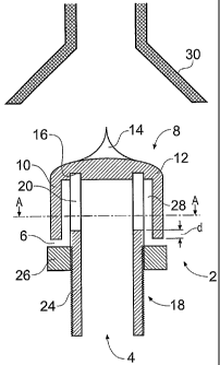
Figures 1 and 2 illustrate a fluidising apparatus
comprising a flow chamber 2 having a fluid inlet 4 and a
fluid outlet 6. The flow chamber 2 comprises a housing
in the form of a cap 8 having a side wall 10 and a top 12
which in the region 14 is generally in the shape of a
cone with. a concave side wall. The underside of the top
12 is provided with an annular recess 16 in which is
located a cylindrical flow guide 18. As best shown in
Figure 2, the upper portion 20 of the flow guide 18 is
provided with a series of tangential slots 22a to 22f.
The lower portion 24 of the flow guide 18 has an external
thread which cooperates with an internal thread formed in
an annular flange 26.
A fluid outlet 6 is defined between the side wall 10 of
the cap 8 and the flange 26 and an annular flow passage
28 is defined between the side wall 10 of the cap 8 and
the upper portion 20 of the flow guide 18. The annular
flow passage 28 is continuous with the fluid outlet 6, so
that the fluid inlet 4 communicates with the fluid outlet
6 by means of the tangential slots 22a to 22f and the
flow passage 28. Directly above the flow chamber 2 is
located a transport outlet 30.
CA 02487698 2004-11-26
WO 03/101868 PCT/GB03/02370
6
In use of the fluidising unit in a pressurised system,
fluid under pressure enters the fluidising unit through
the fluid inlet 4, passes down the flow guide 18 and
exits the flow guide tangentially via the slots 22a to
22f (as~ the open end of the flow guide 18 is closed by
the cap 8). The cap 8 also acts as a swirl enhancer and
is positioned such that its side wa11,10 forms one side
of the said annular flow passage 28 around the tangential
slots 22a to 22f. The cap 8 is longer than the slots 22a
to 22f, such that it overlaps the slots by an amount d
and defines the fluid outlet 6 by which. the concentrated
swirling fluid exits the flow chamber 2. The profiled
region 14 of the cap 8 is shaped in order to encourage a
stable fluid regime above the flow chamber 2. The
swirling flow exiting the flow chamber 2 fluidises, mixes
and breaks up settled or partly settled solids adjacent
to the flow chamber 2, thereby forming a mobile slurry,
which is directed towards the transport outlet 30 from
where it can be directed to a slurry pipeline or for
further processing. The transport outlet 30 may, for
example, comprise a substantially horizontal pipe or a
pipe with a bend (preferably a 90 degree bend), and it
may be funnelled, such that it flares outwardly towards
the flow chamber 2.
The fluidising apparatus may be, fixed within a vessel or
tank at any orientation, passing through the vessel or
tank wall by means of a normal flanged nozzle or threaded
inlet boss, whereby the inlet to the fluidising apparatus
is fed by a fluid under pressure. The outlet 6 of the
fluidising apparatus sets up a swirl that can be created
by, for example, a tangential fluid inlet or inlets,
CA 02487698 2004-11-26
WO 03/101868 PCT/GB03/02370
7
tangential slots or holes in a flow guide, or an auger
unit within the inlet pipe or flow chamber 2. The swirl
from the fluidising apparatus mobilises any settled or
partly settled solids into a slurry mixture. In the case
of a pressurised unit the only exit from the vessel is a.
separate transport outlet 30 which is preferably situated
directly above or under the fluidising unit. The
prepared slurry then reports via the transport outlet 30
to a slurry pipeline, pump or process system as may be
required. In an atmospheric system the outlet duct can
be attached to a pump, or inductor to create the pressure
differential required to transport the slurry to its
required destination.
Figure 3 shows an atmospheric system incorporating a
fluidising apparatus in accordance with the present
invention.
Solids to be transported are loaded into V1. Should
fluids be present in V1 these may be displaced by
incoming solids and will report to the Tank T1 by means
of an overflow.
When V1 is filled with solids the pump is started and the
valve 40 opens to allow fluids to pass through non-return
valve 42 into fluidising unit F1.
Solids will be fluidised and discharged through pipe 44,
due to the vessel operating at atmospheric pressure the
slurry will da.scharge at an equal or less pressure,
controlled by the hydrostatic head of solids/water/slurry
available in V1.
CA 02487698 2004-11-26
WO 03/101868 PCT/GB03/02370
8
The discharging slurry can be fed into an inductor 46 to
provide motive force to deliver the slurry over a short
distance. Feed to the inductor may be from a separate
feed or from the main pump by opening valve 48.
Alternatively the exiting slurry from 44 may be fed into.
the suction of a slurry pump 50 to provide motive force
without further dilution. Using this method will in most
cases reduce the need for large mixing tanks normally
required to feed slurry pumps.
Figure 4 shows a pressurised system using a fluidising
apparatus in accordance with the present invention.
Solids to be transported are loaded into the vessel via a
hopper 58 and valve 60. Fluids in vessel V1 are
displaced by incoming solids and report to the feed tank
T1 via valve 62.
When the vessel is filled with. solids, valves 60 and 62
are closed together with all other valves.
The pump is started and valve 64 is opened to allow fluid
to pass non-return valve 66 and to enter V1 via
fluidising unit F1 to pressurise V1 and solids will
discharge as a slurry through the discharge line 68.
Should the slurry be too dilute then valve 70 may be
opened to cause partial flow to the top of vessel V1 to
compact the solids and cause greater concentration of
solids in the slurry discharge.
In the event that the slurry is too concentrated valve 70
is opened to cause the discharging slurry to be diluted
to suite the process conditions. This can be pre-set or
CA 02487698 2004-11-26
WO 03/101868 PCT/GB03/02370
9
can be operated whilst slurry is discharging until the
set point is reached.
Alternatively valve 70 may be automatic and opening set
by using a signal from a mass density meter installed in
the slurry discharge line.