Note: Descriptions are shown in the official language in which they were submitted.
CA 02487881 2004-11-18
APPARATUS AND METHODS FOR INDUCTION-SFL LOGGING
Cross-reference to related applications
Not applicable.
Statement regarding federally sponsored research or development
Not applicable.
Background of Invention
Field of the Invention
[0001] This invention relates to electrical logging apparatus and methods for
determining the nature and characteristics of the various sub-surface
formations
penetrated by a borehole in the earth.
Background Art
[0002] Various resistivity logging techniques have been used to determine
electrical
properties of sub-surface formations. One commonly used technique is induction-
SFL
(spherically focused laterolog) logging. The induction component of the
induction-
SFL logging measures the resistivity (or its inverse, conductivity) of the
formation by
inducing eddy currents in the formations in response to an AC transmitter
signal. The
eddy currents induce secondary magnetic fields that in turn induce a voltage
in a
receiver antenna. Because the magnitudes of the eddy currents depend on
formation
conductivities, the magnitudes of the received signal thus reflect the
formation
conductivities. The SFL component of the induction-SFL tool measures the
resistivity by injecting a current into the formation and measures the
currents or
voltage drop across a pair of measuring electrodes.
[0003] To obtain true formation resistivity, the log data need to be corrected
for
various effects that influence the measurements. For example, the resistivity
measurements may have unwanted contributions from currents flowing in the
sedimentation layers (beds) lying above and below the layer under
investigation. This
is referred to as shoulder effects, which are particularly problematic if the
layer under
investigation is less conductive than the adjacent beds.
lA
CA 02487881 2004-11-18
100041 To correct the shoulder effects, a sonde response function may be used
to
correlate the voltage measurements with true formation conductivity. This
sonde
response function is also known as the vertical sensitivity curve of the
induction tool.
For homogeneous formations, the sonde response function can best be described
as a
response curve, which has a main lobe of finite width and one or more
sidelobes
located on each side of the main lobe. These sidelobes are responsible for the
shoulder effects.
100051 Several approaches have been proposed to minimize these sidelobes
(hence,
the shoulder effects). For example, U.S. Patent Nos. 2,582,314 issued to Doll
and
3,067,383 issued to Tanguy disclose induction tools having multiple
transmitter and
receiver coils arranged in specific relationships to "focus" the sonde
response function
by narrowing the width of the main lobe and attenuating the sidelobes. In an
alternative approach, U.S. Patent No. 2,790,138 issued to Poupon discloses an
induction logging tool having two separate induction coil arrangements, which
have
the same geometrical center so that responses from the two coil arrangements
may be
used to cancel the contributions from the sidelobes.
[0006] In addition to the shoulder effects discussed above, skin effects may
also limit
the ability of the induction logging equipment to accurately measure the true
conductivity of the formations. The skin effect is characterized by the non-
linear
responses of the sonde response function as a function of the formation
conductivity.
The skin effect results primarily from interactions between different eddy
currents
flowing in adjacent loops in the formation. Prior art has shown that the
magnitudes of
skin effects depend on a complicated function of the coil system operating
frequency,
the effective length of the coil system, and the conductivity value of the
adjacent
formation, among other things.
[0007] To minimize the shoulder and skin effects and to design a better
induction
tool, various factors should be taken into account. These factors include
depth of
investigation (DOI), resolution, borehole effects, frequency of operation, and
mutual
inductance. DOI concerns how far the tool can "see" into the formation from
the
borehole wall. It is desirable that an induction tool is capable of a deep DOI
such that
the measured formation resistivity is unaffected by mud invasion. Typical
invasion
radii range from 0 to 4 feet, but can range up to 8 feet or more. To have a
deep DOI,
1`
CA 02487881 2007-08-22
79350-132
the transmitter-receiver spacing needs to be large. However, large transmitter-
receiver spacing increases the percentage of non-linearity of the responses
resulting
from the skin effects. A large transmitter-receiver spacing also increases
tool length
and cost.
[0008] In addition to the ability to "see" deep into the formation, an
induction tool
should also have high resolution such that the apparent resistivity reading
for the bed
of interest is less affected by adjacent beds. However, to achieve a high
resolution,
the transmitter-receiver spacing needs to be small; this reduces the DOI of
the tool.
Therefore, a compromise is necessary. An alternative to a high resolution tool
is to
use signal processing to enhance the vertical resolution of the tool. For
example, a
method for enhancing the vertical resolution of an induction logging tool is
disclosed
in U.S. Patent Nos. 4,818,946 and 4,837,517, both issued to Barber and
assigned to
the assignee of the present invention.
[0009] An ideal tool should also have little borehole effect in holes with
various
diameters, e.g., ranging from 8 to 16 inches. Alternatively, if the borehole
effect is
non-negligible, means for borehole correction should be provided and the
correction
procedure should be simple. For example, the borehole correction may be
achieved
by including a sensor, e.g., the R,,, sensor on an array induction tool sold
under the
trade name of AITT" by Schlumberger Technology Corporation (Houston, TX), that
provides a measure of the borehole effects.
[0010] The operational frequency of the tool has an effect on DOIs and signal-
to-
noise ratios (SNR). High frequency produces low noise (i.e., better SNR).
However,
high frequency is more susceptible to skin effects (hence, shallower DOI).
Typical
prior art induction tools operate at a frequency ranging from tens of KHz to a
few
MHz.
[0011] Mutual inductance between the transmitter and the receiver coils can
severely
impact the measurable signal magnitudes. Therefore, mutual inductance should
be
kept as low as possible so that it will not obscure the conductivity signals
from the
formation. Mutual inductance can be eliminated or minimized by including a
bucking
coil between the transmitter and the receiver coils. The use of bucking coils
in
induction tools is well known in the art.
2
CA 02487881 2007-08-22
79350-132
[0012] Taking these factors into account, conventional induction tools, such
as that
described in U.S. Patent No. 3,179,879, have evolved to use focused multi-coil
arrays
for measuring resistivities at several DOI. A minimal configuration of such
tools
includes two coil arrays for measuring at two different DOls: a deep array
(ILD) and a
medium array (ILM). The inulti-coil arrays with different DOI can detect and
correct
for environmental effects such as borehole effects and mud invasions. For
example,
the ILD array is designed to see beyond the mud filtrate invaded zone.
[0013] In addition to the improvement in tool designs over the last several
decades,
various signal processing methods have been developed to correct for shoulder
effect.
Exainples of these approaches include phasor processing disclosed in U.S.
Patent Nos.
4,513,376 issued to Barber and 4,471,436, issued to Schaefer et al.
[00141 In addition, U.S. Patent Nos. 4,818,946 and 4,513,376 issued to Barber
disclose methods of processing the induction log measurements to reduce the
unwanted contributions in the log measurements by minimizing the sidelobes in
the
sonde response function used to translate the formation conductivity values
irito the
processed measurements.
[0015] The efforts to improve tool accuracy have resulted in tools that
include many
components and circuitries. As a result, the logging tools tend to be long.
For
example, an induction tool described in U.S. Patent 5,157,605 issued to
Chandler et
al. has a length of approximately forty feet (see FIG. 1A). The increased
length
requires more rig-up time to assemble and insert the logging tools in the
wellbore and
increases the need to drill more rathole (excess footage drilled below the
lower most
zone of interest to enable the logging tool sensors to be positioned deep
enough to
acquire data over the lower section of the zone of interest). In addition, a
long tool
has a tendency of getting stuck in wellbores having poor borehole conditions
and
cannot be placed into wellbores having severe dog legs or horizontal wells
having a
short kickoff radius.
[0016] Therefore, it is desirable to have shorter resistivity logging tools.
One
approach to shorten the tool length is to use a folded antenna array as
disclosed in U.
S. Patent 5,905,379 issued to Orban et al. (shown in FIG. 1B). In the folded
antenna
3
CA 02487881 2007-08-22
79350-132
arrays, the receiver antennas and the bucking coils are all disposed on one
side of the
transmitter antenna, instead of on both sides of the transmitter antenna (see
F1G. lA).
The folded array significantly reduces the length of the tool, i.e., to about
sixteen feet
including the associated electronics. The antenna section length is about 8
feet.
[0017] Induction array tools provide good performance, but they use shallow-
reading
induction antenna instead of galvanic electrodes to measure the near wellbore
resistivity. In "bad hole" conditions (i.e. washed-out or rugose wellbores),
the
electrode devices (e.g., an SFL) can provide better resistivity measurements
than the
shallow-reading induction antennas. In addition, at high resistivities, the
electrode
devices can provide better resistivity measurements than an induction device.
For
these reasons, SFL or other shallow electrode devices are more robust.
Accordingly,
electrode devices are preferred under high resistivity and bad hole
conditions, which
are often found in low-cost wells.
[00181 Another interest in having better induction tools including SFL or
electrode
devices stems from the fact that many old resistivity logs are acquired with
induction-
SFL type devices that measured ILD, ILM and SFL. With the recent interests in
redeveloping old oil fields that have not been developed because of thin pay
zones,
there is a new demand for apparatus and methods that not only can provide
accurate
measurements, but also offer the possibility of well-to-well correlation with
the "old"
induction-SFL measurements.
[0019) Therefore, a need exists for better, but simpler, resistivity logging
tools and
methods for acquiring induction-SFL measurements.
Summary
[0020] In one aspect, embodiments of the invention relate to well logging
tools. A
well logging tool in accordance with one embodiment of the invention includes
an
induction array stack disposed on a mandrel; -an electronic module stack
disposed,
adjacent the induction array stack along a longitudinal axis of the well
logging tool;
and a shallow electrode array arranged on a housing and disposed around the
electronic
module stack, wherein the induction array stack comprises a transmitter
antenna, a
first receiver antenna, and a second receiver antenna spaced apart from each
other
along the longitudinal axis of the well logging tool, the second receiver
antenna being
disposed between the transmitter antenna and the first receiver antenna.
4
CA 02487881 2007-08-22
79350-132
[0021] In another aspect, embodiments of the invention relate to well logging
methods. A method for well logging in accordance with one embodiment of the
invention uses a too] that includes an induction array stack disposed on a
mandrel; an
electronic module stack disposed adjacent the induction array stack along a
longitudinal axis of the well logging tool; and a- shallow electrode array
arranged on a
housing and disposed around the electronic module stack, wherein the induction
array
stack comprises a transmitter antenna, a first receiver antenna, and a second
receiver
antenna spaced apart from each other along the longitudinal axis of the well
logging
tool, the second receiver antenna being disposed between the transmitter
antenna and
the first receiver antenna.
The method includes disposing the tool in a wellbore; acquiring a first
resistivity measurement using the first receiver antenna and a second
resistivity
measurement using the second receiver antenna; acquiring a shallow resistivity
measurement; and processing the first resistivity measurement, the second
resistivity
measurement, and the shallow resistivity measurement to provide a formation
resistivity.
In some embodiments, the induction array stack is no more than 8 feet long.
Brief Description of Drawings
100221 FIG. 1A shows a prior art induction tool having a long antenna array
stack.
[0023] FIG. lB shows a prior art induction tool having a folded antenna array.
[0024] FIG. 2 illustrates a well logging tool according to one embodiment of
the
present invention.
[0025) FIG. 3 shows radial response profiles of the induction arrays according
to one
embodiment of the present invention.
[0026] FIG. 4 is a block diagram showing an implementation of induction phasor
processing.
[0027] FIGs. 5A-5C show comparison logs of measurements acquired using prior
art
tools and a tool according to one embodiment of the present invention.
[0028] FIGs. 6A-6D show comparison logs of measurements acquired using prior
art
tools and a tool according to one embodiment of the present invention,
CA 02487881 2004-11-18
[0029] FIGs. 7A-7C show comparison logs of measurements acquired using prior
art
tools and a tool according to one embodiment of the present invention.
[0030] FIG. 8 is a flow chart of a well logging method according to one
embodiment
of the present invention.
Detailed Description
[0031] The present invention relates to apparatus and methods for measuring
formation resistivity. A logging tool in accordance with embodiments of the
invention has simplified components and yet can provide measurements that are
comparable to more sophisticated tools. In addition, a tool in accordance with
embodiments of the invention is capable of providing depths of investigation
comparable to the prior art tools such that measurements made with tools of
the
invention may be compared with those from other tools. Thus, embodiments of
the
invention use a simple approach to satisfy the industry demand for efficient
and cost
effective apparatus and methods, and at the same time address the desire for
accuracy
of measurement and the possibility of correlating with old well logs.
100321 As noted above, several factors should be taken into consideration in
designing an induction tool. These factors include depth of investigation
(DOI),
resolution, borehole effects, frequency of operation, and mutual inductance.
Embodiments of the invention take into account most of these factors, but use
simple
configurations to achieve the desired results.
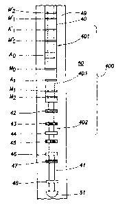
[0033] FIG. 2 shows a tool in accordance with embodiments of the invention
based
on a prior art induction-SFL tool, such as that sold under the trade name of
DITT"" by
Schiumberger Technology Corporation (Houston, TX). As shown, the induction-SFL
tool 400 comprises an induction array stack 402 and a shallow electrode array
401.
The induction array stack 402 provides the measurements similar to the deep-
reading
and medium-reading measurements of prior art induction tools, while the
shallow
electrode array 401 provides the near wellbore resistivity similar to a prior
art SFL
device.
[0034] In the embodiment shown, the induction array stack 402 is disposed on a
mandrel 41, which may be a conductive mandrel as disclosed in U.S. Patent Nos.
4,651,101 and 4,873,488 issued to Barber et al. and assigned to the assignee
of the
6
CA 02487881 2007-08-22
79350-132
present invention. The induction array stack 402 may comprise a transmitter
antenna
42 and a plurality of receiver antennas 44, 46, 48 and bucking antennas 43,
45, 47. As
in prior art folded array induction tools, the induction array stack 402 in
accordance
with embodiments of the invention has the receiver antennas 44, 46, 48 and the
bucking antennas 43, 45, 47 disposed on one side of the tool relative to the
transmitter
antenna 42. For clarity in the description, "antenna" is used herein to refer
to both a
single-coil antenna and a multiple-coil antenna system (e.g., a focused coil
system).
[0035] As shown in FIG. 2, the induction array stack 402 of the present
invention
includes an antenna for deep resistivity measurements. The deep-reading
antenna 48
measures the resistivity far away from the borehole, The deep-reading
measurement
is less affected by mud invasion and the measured resistivity, after any
necessary
correction, can provide true formation resistivity (Rt). As noted above, the
deep DOI
can be achieved with longer transmitter-receiver spacings. However, longer
spacings
necessarily malce the tools longer. A tool in accordance with a preferred
embodiment
of the invention has a deep-reading antenna 48 disposed on the induction array
stack
402 at about 45 inches from the transmitter antenna 42. The about 45-inch
spacing
provides a sufficiently deep DOI without making the tool too long. A bucking
antenna 47 is disposed at an appropriate location (e.g., about 27 inches from
the
transmitter antenna 42) between the transmitter antenna 42 and the deep-
reading
antenna 48 to minimize or alleviate direct couplings (mutual inductance)
between the
transmitter antenna 42 and the deep-reading antenna 48.
[0036] The 45-inch spacing between the transmitter 42 and the deep-reading
antenna
48 is similar to that found on the AITT'". By using a similar configuration as
a
component of an existing tool, the cost of a tool of the invention may be
minimized.
In addition, the 45-inch spacing between the transmitter 42 and the deep-
reading
antenna 48 can provide a DOI that is comparable to the deep readings (ILD) of
old
tools (e.g., DITT"'). If a deeper investigation is desired, the 45-inch
measurements of
the present invention may be combined (negatively) with other measurements
(e.g.,
measurements obtained using a 22-inch array to be described later), according
to
methods known in the art. For methods of combining different DOI measurements
to
achieve a deeper measurement, see for example U.S. Patent No. 5,157,605 issued
to
Chandler et al. and assigned to the assigneP of the present invention.
Thus, a tool of the present invention can
7
CA 02487881 2004-11-18
provide measurements as deep into the formation as the prior art tools with a
much
shorter length.
100371 In addition, a tool of the invention also comprises a medium-reading
antenna
46 disposed in the array stack 402 at about 22 inches from the transmitter
antenna 42.
A bucking antenna 45 is disposed at an appropriate location (e.g., 16 inches
from the
transmitter antenna 42) between the transmitter antenna 42 and medium-reading
antenna 46 to minimize or alleviate direct couplings between these two
antennas.
Again, the 22-inch spacing is based on the existing AITT"" to minimize the
costs of the
tools, while maintaining the ability to provide measurements that are
comparable to
the medium DOI measurements (ILM) acquired using prior art tools (e.g., a dual
induction-SFL tool, sold under the trade name of DITT"' by Schiumberger
Technology
Corporation (Houston, TX)). The ILM acquired with DITTM typically has a DOI of
about 30 inches, which is identical to the DOI provided by the medium-reading
antenna 46 of the tool shown in FIG. 2.
[0038] As shown in FIG. 2, a tool of the invention may optionally include a
short-
reading antenna 44, which is disposed in the array stack at about 12 inches
from the
transmitter 42. The short-reading antenna 44 measures resistivity at a shallow
DOI
(e.g., about 18 inches) that is likely in the mud invaded zone. The short-
reading
antenna 44 is optional because in a conductive mud, an SFL device (to be
described
later) may be used to measure the near wellbore resistivity. However, if a non-
conductive mud (i.e., oil-based mud, OBM) is used, the shallow-reading antenna
44 is
more suitable for measuring near borehole resistivities. The measurement of
the
invaded zone resistivity is important for two reasons: it provides evidence
for mud
invasion, which indicates a formation is permeable; and it provides a value
that can be
used to calculate resistivity porosity after a conrection is made for
unflushed oil in the
invaded zone. A bucking antenna 43 is disposed at an appropriate location
(e.g., 9
inches from the transmitter antenna 42) between the transmitter 42 and short-
reading
antenna 44 to minimize or alleviate direct couplings between these two
antennas.
100391 FIG. 3 shows the radial responses of the induction tool shown in FIG.
2. As
shown, at a geometric factor (GF) of 0.5, the shallow-reading antenna 44, the
medium-reading antenna 46, and the deep-reading antenna 48 have DOIs of about
18
inches, 30 inches, and 61 inches, respectively. Thus, these three antennas 44,
46, and
8
CA 02487881 2004-11-18
48 may be used to simulate an SFL response, an ILM response, and an ILD
response
of the prior art DITT"", respectively.
[0040] The above description for a preferred embodiment of the invention shows
that
the receiver antennas are arranged at certain spacings from the transmitter
antenna.
These particular spacings are selected to be identical to existing tools
(e.g., AITT"") to
minimize the cost of the tool and at the same time preserve the desired
property of the
tool. One of ordinary skill in the art would appreciate that the antennas in
the
induction array stack 402 may also be spaced at other spacings to provide the
desired
measurement characteristics. The invention is, therefore, not limited to the
particular
spacings shown in FIG. 2.
[0041] With transmitter-receiver spacings identical to those found in existing
tools, a
tool in accordance with the invention may use existing electronic components
to
minimize the cost. For example, the embodiment shown in FIG. 2 may use the
same
electronic modules used in AITT"'. Typically, these electronic modules are
arranged in
a stack disposed above the antenna array stack. In addition, the cost of the
induction
array stack 402 may be further minimized if the ceramic spacers (or bobbins)
are
replaced with fiberglass spacers (or bobbins). When using fiberglass spacers,
the
fiberglass cloth is preferably oriented in a way to give a longitudinal
thermal
expansion coefficient that is as low as possible.
[0042) A preferred tool in accordance with the invention comprises one
transmitter
antenna and two or three receiver antennas (the transmitter and the receivers
form
antenna arrays). While additional induction arrays may be included, they
increase the
complexity and cost of the tool. Furthermore, additional antennas may require
the use
of co-wound receiver/bucking coils. For example, the prior art tool shown in
FIG. 1B
uses more complex co-wound receiver/bucking coil arrays. The complexity stems
from the requirement that two criteria must be satisfied at the same time: the
turn ratio
between the turns of a particular receiver coil (N) and its corresponding
bucking coil
(N) must be carefully selected in order to balance or null the direct mutual
coupling
between the transmitter and receiver array; and when the aforementioned turns
ratio is
carefully selected, the receiver coil (N-1) and the bucking coil (N),
associated with
another receiver coil (N), must be co-wound on the same ceramic bobbin at the
same
distance from the transmitter. In contrast, embodiments of the present
invention,
9
CA 02487881 2004-11-18
having simple antenna arrays, do not require the use of co-wound antennas,
i.e., co-
wounding is optional with embodiments of the invention.
[0043] The electronic components for controlling and transmitter antenna 42
and the
receiver antennas 44, 46, 48 may be arranged in an electronic module stack 403
and
disposed adjacent (above or below) the induction antenna array stack 402. In
the
embodiment shown in FIG. 2, the electronic module stack 403 is disposed above
the
induction array antenna stack 402 along the tool axis. As noted above, the
electronic
components for the tool shown in FIG. 2 may use similar electronic modules as
those
found in the existing tools, such as AITT"'. In a preferred embodiment, the
diameter of
the electronic module stack 403 is small such that a housing (sleeve) that
supports the
shallow electrode array 401 may be disposed around the electronic module stack
403
without making the tool diameter too large. In addition, the length of the
electronic
module stack 403 is preferably short such that the overall tool length may be
kept as
short as possible.
[0044] In addition to the induction array stack 402, a tool in accordance with
the
invention also includes a shallow electrode array 401. The shallow electrode
array
401 is for measuring near wellbore resistivity, e.g., at a DOI of about 18
inches. One
of ordinary skill in the art would appreciate that other electrode array
configurations
are possible to achieve the desired measurements.
[0045] In accordance with one embodiment of the invention, the shallow
electrode
array 401 may be based on a feed back controlled spherically focused laterolog
(SFL)
device. The shallow electrode array 401 comprises current return electrodes A,
and
A'1, monitor electrodes Mo and M'o, and measurement electrode pairs Mi, M2 and
M' J, M'2, all symmetrically disposed on both sides of a central current
electrode Ao as
shown in FIG. 2. In a preferred embodiment, all these electrodes are arranged
on an
insulated housing 40 that is disposed over the electronic module stack 403,
which is
also mass-isolated and insulated.
[0046] The shallow electrode array 401 shown in FIG. 2 is similar to a prior
art SFL
device. However, the overall length of the shallow electrode array 401 is
shorter
(e.g., about 6 feet) than a typical SFL device (about 10 feet). Furthermore,
to
minimize the dimension of the tool, the shallow electrode array 401 may share
the
same electronic module stack 403 with the induction array stack 402. For
example,
CA 02487881 2007-08-22
79350-132
the central current electrode Ao) may be coupled to the induction transmitter
42 and the
electrode measurement circuitry for other electrodes may be shared with that
for the
receiver antennas 44, 46, 48. With the shared circuitry, a constant power
arrangement, similar to that used in the high-resolution azimuthal laterolog
sondes,
sold under the trade name of HALST"' by Schlumberger Technology Corporation
(Houston, TX), may be used to limit the dynamic range of the voltage
measurements.
The constant power arrangement may be switched out for the induction
transmitter, if
necessary. The high-resolution azimuthal laterolog sonde technology is
disclosed, for
example, in U.S. Patent Nos. 5,754,050, issued to Smits et al., 5,852,363,
issued to
Smits, 6,046,593, issued to Eisenmann et al., and 6,369,575, issued to
Eisenmann et al.
[0047] While the above description is based on an SFL-based electrode array,
one of
ordinary skill in the art would appreciate that a tool in accordance with
embodiments
of the invention may also be based on other electrode array configurations,
such as a
shallow electrode array of the high-resolution laterolog array tool sold under
the trade
name of HRLAT " by Schlumberger Technology Corporation (Houston, TX).
[0048] As in a prior art SFL, the shallow electrode array 401 shown in FIG. 2
operates with two current modes: an auxiliary current from the central
electrode Ao to
the current return electrodes AI, A>>; and a survey (investigation) current
from the
central electrode Ao to a current return located at a distance from the
shallow
electrode array 401. In a prior art SFL (e.g., the SFL device on the DITT""
tool), the
survey current returns to the tool body above the tool. However, with the
electronics
housing mass-isolated and insulated in a tool according to embodiments of the
invention, an electrode (which may be mass-isolated) may be used in the
topmost tool
in the string to provide current returns.
[0049] During logging, auxiliary currents are emitted from the central current
electrode Ao and returned to current return electrodes Al and A'. The
auxiliary
currents force the survey currents into the formation to form an approximately
spherical shape on the equipotential surfaces within the formation. The
focusing
condition is obtained when the readings at Mi and M_, are identical. One of
ordinary
skill in the art would appreciate that the monitoring and maintaining the
focused
11
CA 02487881 2007-08-22
79350-132
condition may be software controlled to minimize hardware requirement (hence,
the
dimensions of the tool). However, hardware may be used if so desired,
[00501 A tool in accordance with embodiments of the invention may optionally
include an electrode 51 at the end of the tool to measure mud resistivity.
This
electrode 51 is similar to the R,,, sensor of the AITTA4 tool. It has been
shown that the
arrangement of the sensor at the bottom of the tool is much less sensitive to
proximity
effects of the borehole wall. Thus, the measurements acquired by electrode 51
may
be used to correct borehole and mud effects according to methods known in the
art,
for example, using look-up tables.
[0051] According to the embodiment described in FIG. 2, the induction array
stack
402 length is about 45 inches. This length together with 12 inches on either
side of
the array stack 402 makes the tool about 63 inches (about 5.3 feet) long. This
length
is much shorter than that of AITT"" (about 8 feet) or that of DITT"" (about 13
feet). The
shallow electrode array 401 of the invention is about 6 feet long, which
together with
the both end sections makes the tool about 8 feet long. This length is shorter
than that
of a typical prior art SFL device (about 10 feet long). Thus, the total length
of the tool
400 according to one embodiment of the invention may be as short as 13 feet,
which
is much shorter than most prior art induction-SFL tools (typically 15 feet or
longer).
[0052] After acquisition, the conductivity measurements may be corrected for
various
environmental effects using conventional processing methods. For example, skin
effects may be reduced by phasor processing of the individual array
measurements.
Phasor processing is disclosed in U.S. Patent No. 4,513,376 issued to Berber
and
assigned to the assignee of the present invention.
Briefly, in phasor processing, a filtering function is applied
to the quadrature-phase X component of each log measurement to obtain a
correction
factor representative of the change in the sonde response function as a
function of
formation conductivity. The correction factors are then summed with the in-
phase R
components to provide a skin effect compensated log.
[0053] Similarly, U.S. Patent No. 4,471,436 issued to Shaefer et al. discloses
methods
for correcting shoulder effects and skin effects using phasor processing. This
patent is
assigned to the assignee of the present invention.
Shoulder effect is reduced by generating a spatial deconvolution filter
12
CA 02487881 2007-08-22
79350-132
that, when convolved with the sonde response function, sharpens the main lobe
and
reduces the sidelobes to near zero. Other methods for enhancing the resolution
of an
induction logging tool may be found in U.S. Patent Nos. 4,818,946 and
4,837,517,
both issued to Barber and assigned to the assignee of the present invention.
In addition, borehole
corrections may also be corrected using methods known in the art, e.g., by
using look-
up tables.
[0054] FIG. 4 illustrates a typical induction logging system, which may be
implemented in a tool according to embodiments of the invention. As shown in
FIG.
4, an induction logging tool 30 is suspended in a borehole 26 by some means of
conveyance 28 (the means related to any wireline, logging-while-drilling or
measurement-while-drilling technique). The tool 30 is powered by power supply
10
and includes a sonde 31 with a three-coil induction array including a
transmitter T and
two receivers R, and R2. The sonde 31 has a sonde response function g(z, 6F),
which
maps the formation conductivity 6F(z) into the log measurements. Tool 30 also
includes a phase sensitive detector 32 which responds to signals from the
transmitter
oscillator 34 and the received signals from receivers Ri and R~ to generate
the in-
phase, 6R(z, (yr), and quadrature-phase, 6x(z, 6F), components for each log
measurement.
[0055] A processing unit 12, which may be a general purpose programmed
computer,
includes a demux 16, which separates the two components of each log
measurement
received from the tool 30. The in-phase coinponent is applied to deconvolution
filter
means 18 and provisionally to summation means 24. The quadrature-phase
component may be applied to linear filter means 20, as described in U.S.
Patent
4,513,376 issued to Barber. Deconvolution filter ineans 18 implements a filter
response function h(z) based on the geometrical factor response function
goF(z). The
output of filter 18 is deconvolved conductivity measurement GD(j) and
represents a
processed measurement. The output from filter 18 is applied to summation means
24,
and to recorder 14 for possible recording as a processed log. Provisionally
applied to
summation means 24 is the in-phase component measurement from demux 16. When
used in conjunction with the phasor processing of the quadrature-phase
component
6P(j), an improved induction log may be obtained either by summing (YP(j) with
aD(j)
or with 6R(z, 6F) directly.
13
CA 02487881 2004-11-18
100561 One of ordinary skill in the art would appreciate that any other
appropriate
processing method that is known in the art may also be used in place of or in
addition
to the method presented herein. Additionally, with three depths of
investigation in
either conductive (water-based) or non-conductive (oil-based) mud, step-
profile
invasion inversion can be provided at this stage by using an appropriate
algorithm.
Also, the processing required to negatively combine a small weight of the
twenty-two
(22) inch array with the forty-five (45) inch array to simulate the ILD might
be done
at this point. Finally, other basic processing may be used to apply typical
environmental corrections, for example temperature, hole size, mud resistivity
etc.
100571 An extensive set of formation models has been developed in the industry
to
test induction logging tools and processing methods. Three of these models,
the
Oklahoma formation model, the Gulf of Mexico formation model, and the Conoco
test well, were used to illustrate the capabilities of a tool of the present
invention. The
responses of a tool shown in FIG. 2 can be derived from measurements acquired
with
the AITT"' 12, 21, and 39-inch arrays and processed with the AITT"" Recovery
algorithm. These responses are compared with the responses of the AITT"" and
the
prior art DITT ". The AITT"" measures an array of conductivities, including
ten (10)
inch, twenty (20) inch, thirty (30) inch, sixty (60) inch and ninety (90) inch
depths of
investigation. The DITT"^ measures SFL at a DOI of about 18 inches, ILM at a
DOI of
about a 30 inches, and ILD at a DOI of about 61 inches.
100581 FIGs. 5A-5C, FIGs. 6A-6D and FIGs. 7A-7C show comparison logs produced
by different tools using the three formation models. Each log depicts various
curves
from a designated tool: the DITT"", the AITT" and a tool of the present
invention. The
curves presented on these logs include resistivities (ohm-m), true resistivity
Rt, hole
diameter (inches), the log interval (feet), and a radius of invasion r,
(inches). In
addition, the logs depicted in FIGs. 6A-6D and FIGs. 7A-7C also show an
invaded (or
transition) zone resistivity curve R,o.
100591 FIGs. 5A-5C are logs produced using the Oklahoma formation model. FIG.
5A is a DITT"' Standard log. It is clear from this log that this tool does not
produce
accurate true resistivity (Rt). This is most apparent in the 20-foot log
interval
between 110 feet and 130 feet. The inaccuracy of both the ILM and the ILD
measurements in this high resistivity region is apparent even when bed
resolution is
14
CA 02487881 2004-11-18
not an issue. In contrast, the AITT"^ log in FIG. 5B illustrates a near
perfect log
response over a full range of resistivities, including the 20-foot interval
between 110
feet and 130 feet. Also, note the step-like profile seen on the AITT"' log vs.
the
smooth curves seen on the DITT"' log. The different curve characteristics,
along with
the large discrepancy in the measured resistivities, may render it difficult
to make
well-to-well correlation between the new AITT" log and the old DITTM log.
100601 In FIG. 5C, a tool of the present invention provides a log that is
close to the
log of the more sophisticated AITT"'. Note that a tool of the present
invention
achieves this result with only two induction arrays and an SFL device, whereas
the
AITT"' uses five induction arrays. It is apparent from the log in FIG. 5C that
the
shoulder effects in the log obtained using a tool of the present invention
have been
fully corrected. Therefore, the formation resistivities estimated from logs
obtained
using a tool of the present invention should be more accurate than those
derived from
DITT"" logs.
[0061] FIGs. 6A-6D show comparison logs produced using the Gulf of Mexico
formation model, which has a pay zone (40-60 ft) with RXo < Rt invasion, a
transition
zone (60-90 ft), and a water zone (90-110 ft). FIGs. 6A-6C show the DITT""
Standard
log, the AITT"" log, and the log obtained using a tool of the present
invention,
respectively. All three logs provide similar resistivity profiles. However, in
the water
zone with mud invasion (90-110 ft), the SFL devices of the DITT"' and a tool
of the
present invention provide more accurate invaded zone resistivities (R,,o). If
a tool of
the present invention is equipped with a shallow-reading antenna, it may be
used
instead of the SFL device in an OBM well, as shown in FIG. 6D.
100621 FIGs. 7A-7C show logs produced using the Conoco test well. This well is
in
bad shape and the wash-outs are modeled as "invaded" zones having an invaded
zone
resistivity identical to the mud resistivity, i.e., RXO = Rm. FIGs. 7A-7C show
the
DITT" traditional logs, the AITT"' logs, and the logs obtained using a tool of
the
present invention, respectively. In most part, all three tools seem to produce
comparable logs, except for the near wellbore measurements in the interval
between
45 feet and 70 feet, where low-resistive invasion occurred. Interestingly, the
SFL
readings of both the DITT" and a tool of the present invention produce similar
results,
while the 10-inch induction array of the AITT'" produced a different reading.
Thus, a
CA 02487881 2004-11-18
tool of the present invention may be more useful than AITT" in well-to-well
correlations between the new logs and the old DITT"' logs.
[0063] FIG. 8 is a flow chart illustrating a method 80 of well logging
according to one
embodiment of the invention. The process starts by disposing a well logging
tool
according to one embodiment of the present invention in a wellbore (step 82).
The
tool comprises an induction array stack and a shallow electrode array. Next, a
series
of induction measurements are taken as well as a galvanic electrode
measurement
(step 84). The acquired data are then processed in order to provide a
resistivity
measurement with accuracy that is comparable to state of the art technology
and at the
same time providing a formation resistivity profile with comparable
characteristics to
that of old induction-SFL logs (step 86).
100641 The advantages of the present invention include efficient apparatus and
methods through reduced tool length. A tool in accordance with the invention
allows
wells to be drilled with less rathole, which in turn reduces drilling time. A
shorter
tool has a lower risk of sticking. In addition, a shorter tool string may
improve the
chance of reaching the bottom of the well, particularly when there are doglegs
or
curvatures in the well. The result is quicker operations and in turn
significant rig time
savings. A tool in accordance with the invention also requires less frequent
sampling
interval, which allows for a logging speed that may be as much as twice that
of a
comparable tool, e.g. an AITT".
100651 Furthermore, embodiments of the invention can provide measurements that
permit well-to-well correlations for analysis of remaining hydrocarbon
reserves in old
oil and gas fields.
[0066] While the invention has been described with respect to a limited number
of
embodiments, those skilled in the art, having benefit of this disclosure, will
appreciate
that other embodiments can be devised which do not depart from the scope of
the
invention as disclosed herein. Accordingly, the scope of the invention should
be
limited only by the attached claims.
16