Note: Descriptions are shown in the official language in which they were submitted.
CA 02488225 2004-11-23
ZM0578 Antony J. Lozier
Nicolas J. Pacelli
Sarah L. Thelen
EXPANDABLE REAMER
BACKGROUND
[0001 ] The present invention relates to reamers and, more specifically, to
reamers having
expandable reaming heads.
[0002] Reamers are typically used for enlarging the diameter of a bore which
has been
drilled or otherwise cut in a material. Reamers generally include a shank for
driving the
reamer and a reamer body that includes cutting edges. Hand or powered rotation
of a
reamer cuts or shaves the material surface defining the bore, removing
material and
increasing the diameter of the bore.
[0003] Certain reaming applications require the reaming of a cavity that is
larger in
diameter than an aperture allowing access to the cavity. One known expandable
reamer
used for spinal surgical procedures provides an elongated shaft assembly
having a pair of
opposing blades rotatably mounted in a scissor-like fashion at the distal end
of the shaft
assembly. After insertion of the distal end of the shaft assembly through an
aperature
leading to a bore in a bone structure, the blades may be rotated radially
outwardly to
increase the effective cutting diameter of the reamer. After reaming a cavity
of the
desired size, the reamer blades may be rotated to a position in which the
outer diameter of
the blades is less than the aperature diameter to allow for withdrawal of the
reamer from
the bone structure.
[0004] Orthopedic procedures for the replacement of all, or a portion of, a
patient's joint
generally require an.open procedure wherein an incision is made through the
skin and the
underlying muscle and other tissue to fully expose the relevant joint. While
this approach
provides surgeons with an excellent view of the bone surface and open access
for various
sized and shaped instruments such as cutting and reaming instruments, the
underlying
damage to the soft tissue, including the muscles, can lengthen a patient's
healing and
rehabilitation time after surgery. Therefore, it is desirable to minimize the
size of the
incision and the damage to the underlying muscle.
[0005] What is needed in the art is a method and device for reaming bone
cavities which
are larger than the incision of the soft tissue and/or aperture into the bone,
and without
requiring expensive and separate boring and reaming instruments.
-1-
CA 02488225 2004-11-23
SUMMARY OF THE INVENTION
(0006] The present invention provides a method and device for cutting a cavity
in a
structure, the cavity having a greater diameter than the aperture providing
access to the
cavity. The method and device of the present invention may be used, for
example, for
cutting a cavity in a bone structure using minimally invasive surgical
procedures, for
example, for performing a minimally invasive total hip arthroplasty.
(0007] An exemplary embodiment of an expandable reamer according to the
present
invention may include a cannulated shaft and a plurality of straight cutting
blades coupled
to the cannulated shaft and having deformation points. The blades of this form
of the
present invention are outwardly deformable between a contracted position and
an
expanded position. In the contracted position, the blades are substantially
parallel to the
longitudinal axis of the cannulated shaft and, in the expanded position; the
blades have at
least a portion oriented radially outward from the longitudinal axis of the
cannulated shaft,
thereby forming a larger diameter cutting surface in the expanded position
than in the
contracted position.
(0008] The blades may be formed from a portion of the cannulated shaft by
milling,
etching, stamping, or otherwise forming longitudinally oriented slots through
the wall of
the cannulated shaft, the slots serving as flutes dividing the cutting edge
and trailing edge
of each adjacent blade. Each blade may be segmented along its length, the
segments
separated at a point of deformation. The location of deformation points
provide a desired
shape to the cutting surfaces when the reamer body is placed in the expanded
position.
(0009] The reamer may be expanded by drawing the distal end of the reamer
blades
toward the proximal end of the blades, and may be contracted by advancing the
distal end
of the blades away from the proximal end of the blades. Advantageously, the
expandable
reamer may be used for cutting a cavity in a bone or other structure that is
larger than the
diameter of the soft tissue incision and aperture into the bone and greater
than the
diameter of the contracted reamer.
(0010] In one exemplary embodiment, an expandable reamer of the present
invention
includes a cannulated shaft defining a shank and a reamer body. The reamer
body defines
a plurality of blades having longitudinally extending slots therebetween and
an end cutter
disposed at the distal end of the reamer body. Distal ends of the blades may
be coupled to
a ring on which the end cutter is positioned. Proximate ends of the blades are
coupled to
the shank. The blades may be deformable at the point of coupling with the ring
and shank.
-2-
CA 02488225 2004-11-23
The length of the blade may be divided into two or more segments, the segments
separated by a deformation point.
[0011] By proximally drawing the ring and distal end of the blades toward the
proximate
end of the blades, deformation of the blades at the deformation points allows
the
segments to extend radially outward from the longitudinal axis of the reamer,
thereby
increasing the diameter of the reamer body. Distally advancing the distal ring
along the
longitudinal axis away from the proximate end of the blades will cause the
blades to
contract radially inward toward the longitudinal axis, thereby returning the
reamer body
to its original diameter and the blades to a contracted position substantially
parallel to the
longitudinal axis of the reamer.
[0012] In one exemplary embodiment, the deformation points at which the blades
are
coupled to the distal ring and to the shank and which separate adjacent blade
segments
may be defined simply by exterior or interior circumferential reliefs or
grooves which
reduce the material thickness and therefore reduce resistance of the blades to
bending at
the various desired points. The deformation points may also be further defined
by
radially oriented arcuate cuts which intersect the circumferential reliefs.
[0013] In one exemplary embodiment of the invention, the blades are easily and
inexpensively formed from a reamer body having a polygonal cross-section, such
as a
hexagon. The slots may be milled parallel to and coincident with the apex
formed
between adjacent sides of the polygon. By locating the slots in this way, each
apex and
the milled face which extends radially inward form cutting edges, and the
opposite milled
face of the slot forms the trailing edge, or flute, of an adjacent blade.
Formed in this
fashion, the cutting edge, being the former apex of the polygon, has a greater
radius than
the trailing edge. Thus, only the cutting edge contacts the surface being
reamed.
[0014] The expandable reamer of the present invention is an inexpensive and
possibly
disposable device. The deformation points of the reamer body of the present
invention
can be positioned to form predefined complex shapes for boring and reaming a
cavity in a
bone as part of a minimally invasive orthopedic surgery. Such procedures
include, for
example, those disclosed in "Method and Apparatus for Reducing Femoral
Fractures,"
U.S. Patent Application Serial No. 10/155,683, filed May 23, 2002; U.S. Patent
Application Serial No. 10/266,319, filed October 8, 2002; U.S. Patent No.
10/358,009,
filed February 4, 2003; and "Method and Apparatus for Performing a Minimally
Invasive
Total Hip Arthroplasty," U.S. Patent Application Serial No. 09/558,044, filed
April 26,
2000; U.S. Patent Application Serial No. 09/992,639, filed November 6, 2001,
and
-3-
CA 02488225 2004-11-23
published as U.S. Publication No. US 2002/0099447 A1; U.S. Patent Application
Serial
No. 10/053,931, filed January 22, 2002, and published as U.S. Publication No.
US
2002/0116067 A1, on August 22, 2002, and U.S. Patent No. 10/357,948, filed
February 4,
2003; the disclosures of which are hereby incorporated by reference herein.
(0015] In order to ream a cavity in a bone that is larger than the incision in
the soft tissue
and the entry aperture into the bone, the expandable reamer is first inserted
through the
incision and the aperture in the bone. Then, the reamer is expanded during
rotation by
drawing a distal end of the reamer body toward the proximate end of the reamer
body.
Upon achieving the desired expansion diameter and thereby cavity size, the
distal end of
the expandable reamer may be advanced away from the proximate end of the
reamer body,
thereby collapsing the diameter of the expandable reamer so that it may be
removed from
the cavity and withdrawn through the entry aperture and incision.
(0016] Other embodiments of the expandable reamer are also envisioned. One
such
embodiment includes a reamer having blades that are uncoupled at a distal end,
thus
providing a larger cavity diameter at the distal end of the cavity. Another
embodiment
includes reamer blades that are flexibly biased to the expanded position,
thereby
providing a reamer that will expand and cut less dense or cancellous bone
while
contracting away from more dense cortical bone. Yet another embodiment expands
to
one of various predefined shapes according to the blade segment length and
deformation
members coupling the blade segments.
(0017] In one embodiment, a reamer according to the present invention includes
a shank,
a reamer body having a longitudinal axis, and a blade formed in said reamer
body, the
blade deformable between a contracted position and an expanded position.
(0018] In another embodiment, a reamer according to the present invention
includes a
shank, a reamer body having a longitudinal axis, a blade formed in the reamer
body, and
deformation means for deforming the blade between a contracted position and an
expanded position.
(0019] In another embodiment, a reamer according to the present invention
includes a
cannulated shaft having a wall, a proximate end and a distal end and defining
a
longitudinal axis, the cannulated shaft having a plurality of slots
therethrough, the
plurality of slots extending from the distal end toward the proximate end, and
a plurality
of blades, each one of the plurality of blades defined by the wall between
adjacent ones of
the plurality of slots.
-4-
CA 02488225 2004-11-23
[0020] In yet another embodiment, a method of reaming a cavity in a bone
according to
the present invention includes providing an expandable reamer having blades
moveable
between a contracted position and an expanded position, boring an opening in
the bone,
the opening having a diameter at least as large as a diameter of the
expandable reamer in
a contracted position, inserting the expandable reamer into the opening, the
expandable
reamer being in the contracted position, rotating the expandable reamer while
moving the
blades to the expanded position, contracting the expandable reamer to the
contracted
position, and removing the expandable reamer from the cavity.
[0021] Advantageously, the present invention provides a low-cost and
potentially
disposable reamer that provides a predefined reamer body shape which is
expandable
after insertion into the bone structure, which includes deformable blades that
are secured
at both a distal and a proximate end, and which may include a distal end
cutter for boring
the initial bore into the bone structure.
BRIEF DESCRIPTION OF THE DRAWINGS
[0022] The above mentioned and other features and objects of this invention,
and the
manner of attaining them, will become more apparent and the invention itself
will be
better understood by reference to the following description of embodiments of
the
invention taken in conjunction with the accompanying drawings, wherein:
[0023] Fig. 1 is a perspective view of a first exemplary embodiment expandable
reamer
according to the present invention;
(0024] Fig. 2 is a cross-sectional view of the reamer of Fig. 1;
[0025] Fig. 3A is a perspective view of the reamer of Fig. 1 coupled with a
driving
apparatus, the reamer shown in a contracted position;
[0026] Fig. 3B is a partial perspective view of the reamer of Fig. 3A, shown
in an
expanded position;
[0027] Fig. 4 is a partial cross-sectional view of the reamer of Fig. 3A,
shown in the
contracted position;
[0028] Fig. 5 is a radial plan view of a second exemplary embodiment according
to the
present invention;
[0029] Fig. 6 is a partial cut-away anterior view of a femur with the reamer
of Fig. 5
being employed in a minimally invasive surgical procedure for removing the
neck and
head of the femur; and
-S-
CA 02488225 2004-11-23
(0030] Fig. 7 is a partial perspective view of a third embodiment expandable
reamer
according to the present invention.
[0031] Corresponding reference characters indicate corresponding parts
throughout the
several views. Although the drawings represent embodiments of the present
invention,
the drawings are not necessarily to scale and certain features may be
exaggerated in order
to better illustrate and explain the present invention. The exemplification
set out herein
illustrates embodiments of the invention, in several forms, and such
exemplifications are
not to be construed as limiting the scope of the invention in any manner.
DESCRIPTION OF THE INVENTION
(0032] The embodiments disclosed below are not intended to be exhaustive or
limit the
invention to the precise forms disclosed in the following detailed
description. Rather, the
embodiments are chosen and described so that others skilled in the art may
utilize their
teachings.
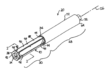
[0033] First exemplary expandable reamer 20, shown in Fig. 1, is formed from
cannulated shaft 22 having bore 24 therethrough along longitudinal axis 26.
Reamer 20
includes shank 28 and reamer body 30. Chuck end 32 for driving reamer 20 is
located at
proximate end 34 of shank 28. Reamer body 30 extending from distal end 36 of
shank 28
to distal end 38 of reamer 20 includes deformable cutting blades 40 and ring
42. Blades
40 are coupled at proximate end 44 to distal end 36 of shank 28. Blades 40 are
also
coupled at distal end 46 to ring 42. Advantageously, as ring 42 is proximally
drawn
toward proximate end 32 of reamer 20, at least a portion of blades 40 extend
radially
outward from longitudinal axis 26, thereby increasing the cutting diameter of
reamer 20.
[0034] Expandable reamer 20 is useful for cutting a chamber or cavity in a
structure, the
cavity having a greater diameter than the entry aperture into the structure
and a greater
diameter than shaft 22. Referring to Fig. 6, for minimally invasive surgery,
e.g., total hip
arthroplasty, expandable reamer 120 may be inserted through incision 50
defined in soft
tissue 52 and through aperture 60 and into bore 54 drilled in bone structure
56 of femur
58. Optionally, to further protect soft tissue 52, a tubular retractor (not
shown) may be
inserted through incision 50, with reamer 120 inserted through the tubular
retractor to
prevent contact of soft tissue 52 with blades 140. In one exemplary
embodiment, the
tubular retractor is coupled to bone structure 56 and further functions to
guide insertion of
reamer 120.
-6-
CA 02488225 2004-11-23
[0035] After blades 140 of expandable reamer 120 are located with bore 54,
blades 140
may be extended to an expanded position while rotating reamer 120, thereby
forming
cavity 62 in bone structure 56. For example, such a procedure using reamer 120
may be
used to remove neck 64 and head 66 of femur 58.
(0036] Referring to Figs. 1 and 2, first exemplary expandable reamer 20
includes six
blades 40 and ring 42 which are formed from cannulated shaft 22. In this
exemplary
embodiment reamer body 30 has a hexagonal cross-section. The cross-section of
reamer
body 30 may be a circle or a different numbered polygon with the number of
sides
determining the number of resulting blades 40.
[0037] Referring to the cross-sectional end view shown in Fig. 2, blades 40
are formed by
removing portion 70 which is coincident with one side of corner or apex 72
joining
adjacent sides of the hexagon. Removing portions 70 creates slots 74 between
adjacent
blades 40. Slots 74 are milled in reamer body 30 so that face 76 is directed
radially
toward longitudinal axis 26. The wall of slot 74 opposite face 76 defines the
trailing edge
or heel 78 of the adjacently located blade 40. The remaining portion of the
hexagonal
side located between cutting edge 72 and heel 78, referred to as land 80,
forms the outer
surface of each blade 40. Inner surface 82 of blades 40 defines bore 24 formed
through
reamer body 30.
(0038] Because slot 74 is located coincident to two adjoining sides of the
hexagonal
shape of reamer body 30, cutting edge 72 has a greater radius relative to
longitudinal axis
26 than any other point along land 80. Thus, clearance angle 83, defined as
the difference
in radius between cutting edge 72 and trailing edge 78, is provided so that
cutting edge 72
of each blade 40 is the only portion of blades 40 that will be in contact with
the material
being reamed. First exemplary reamer 20 shown in Fig. 2 is formed for
counterclockwise
rotation 84, which rotates cutting edge 72 and face 76 toward the surface to
be reamed.
[0039] Referring now to Figs. 1 and 4, outward radial expansion of portions of
blades 40
is facilitated by deformation points 86. Each blade 40 is divided into
proximal
segment 88 and distal segment 90. Segments 88 and 90 are joined at deformation
points
86. Deformation points 86 defined in blade 40 may be formed by interior
circumferential
relief 92 which is cut along interior surface 82 of each blade 40 and which
reduces the
resistance of blade 40 to bending or deforming outwardly.
[0040] Additionally, proximal segment 88 of each blade 40 is joined to shank
28.
Deformation points 87 are formed by proximal exterior circumferential relief
94 cut in
land 80 of each blade 40. Similarly, deformation points 87 are located in
blade 40 where
_7_
CA 02488225 2004-11-23
distal segment 90 of each blade 40 is connected to distal ring 42 of reamer
body 30.
Deformation points 87 may be formed by distal exterior circumferential relief
96 cut in
each land of blade 40. Additionally, radially oriented arcuate notches 95
(Fig. 1 ) may be
cut in blades 40 along cutting edge 72 and coincident with reliefs 92, 94, and
96, further
reducing the resistance of blades 40 to bending to the expanded position.
Although
deformation points 86 and 87 are referred to as "points," deformation points
86 and 87
define lines or areas of deformation in blades 40.
[0041] Referring to Fig. 3B, interior relief 92 and notches 95 are provided
between
segments 88 and 90 and exterior reliefs 94 and 96 and notches 95 are provided
at the
proximal end 44 of segment 88 and distal end 46 of segment 90. Reliefs 92, 94
and 96
and notches 95 facilitate folding or radially expanding the adjoining ends of
segments 88
and 90 at interior relief 92 outwardly from longitudinal axis 26 and about
proximate relief
94 and distal relief 96. Alternatively, other types of deformation points as
are known in
the art may be utilized to hingably connect blade segments 88 and 90. For
example, a
material or discrete member that is more easily deformable than blades 40 may
be
substituted at the points of deformation, the material at the points of
deformation may be
thinned or otherwise made pliable, or a hinge or other type of relative motion
device or
member may be utilized. If a point of deformation comprises a thinned region,
then the
cross-sectional area at the point of deformation is smaller than the cross-
sectional area of
the portions of the blade adjacent the deformation point.
[0042] Referring to Fig.4, mechanism 100 provides proximal translation of ring
42
toward distal end 36 of shank 28, thereby expanding blades 40 as described
above.
Mechanism 100 may comprise, for example, bushing 102, which may be rotatably
coupled to ring 42, and elongate member 104, for example, a rod. Elongate
member 104
extends through bore 24 in expandable reamer 20 and is operable to translate
ring 42
along longitudinal axis 26. Exemplary driving device 106, shown in Figs. 3A
and 4, may
be utilized to rotationally drive reamer 20 and to longitudinally translate
elongate member
104. Driving device 106 includes handle 108, rotational drive 110 and
translational drive
112; however, other devices or mechanisms capable of effecting rotational and
translational motion may be utilized.
[0043] As shown in Fig. 4, rotational drive 110 of driving device 106 may be
coupled
with chuck end 32 and translational drive 112 may be coupled with elongate
member 104.
Referring to Fig. 3A, first actuator 114 functions to rotate rotational drive
110 and thus
reamer 20 about longitudinal axis 26. Second actuator 116 functions to
translate
_g_
CA 02488225 2004-11-23
translational drive 112 and thus elongate member 104 and bushing 102 along
longitudinal
axis 26. By actuating second actuator 116 in a first direction, bushing 102 is
drawn
toward distal end 36 of shank 28, thereby deforming blades 42 radially
outwardly to the
expanded position shown in Fig. 3B. Actuating second actuator 116 in a second
direction
distally advances elongate member 104 and bushing 102 away from distal end 36
of
shank 28, thereby returning blades 40 to the contracted position,
substantially parallel to
longitudinal axis 26 as shown in Fig. 3A.
[0044] Refernng to Fig. 5, second exemplary expandable reamer 120 includes
cannulated
shaft 122 defining shank 128, Chuck end 132, reamer body 130, distal ring 142,
and end
cutter 144. End cutter 144 may be secured to ring 142 and may be used as an
end mill to
cut the bore which reamer 120 may then ream into a larger diameter cavity.
(0045] Reamer body 130 includes blades 140 which are divided into multiple
blade
segments 188, 190, 192, and 194. Advantageously, the relative length and
locations of
segments 188-194 and deformation members 186 joining them may be designed to
provide a specific desired shape and diameter of reamer 120 when in the
expanded
position shown in Fig. 5. For example, an exemplary reamer may have two short
segments coupled to opposite ends of a central long segment, thus providing a
long
cutting surface of uniform diameter between the distal and proximal ends of
the blades.
An exemplary reamer may alternatively have a single segment formed from
pliable
material which bows outwardly between the proximal and distal ends when
compressed.
[0046] Refernng to Fig. 6, advantageously, expandable reamer 120 may be used
to cut
cavity 62 in bone structure 56 while maintaining minimally invasive surgical
procedures.
For example, incision 50 may be cut in soft tissue 52, a cylindrical sleeve
(not shown)
may be positioned through incision 50 to hold open incision 50 and protect
soft tissue 52
from damage by reamer 120, and then a drill or end cutter 144 of expandable
reamer 120,
may be used to form aperture 60 and bore 54 in bone structure 56 of femur 58.
[0047] In certain orthopedic procedures, it is necessary to cut large diameter
cavity 62 in
bone structure 56, which may be, for example, femur 58. After bore 54 is
formed in bone
structure 56, reamer 120 may be inserted through incision 50 and aperture 60
into bore 54.
While driven rotationally, blades 140 are expanded so that blades 140 ream
bore 54 to an
increased diameter, thus forming cavity 62. Cavity 62, having been formed by
reamer
120 in an expanded position, has a larger diameter than the diameter of
aperature 60 and
incision 50. After cavity 62 is reamed to the desired diameter, blades 140 of
reamer 120
may be contracted to their original diameter as described above, and reamer
120 removed
-9-
CA 02488225 2004-11-23
through aperture 60 and incision 50. Debris from removed bone structure 56 may
then be
flushed or otherwise removed from cavity 62 in hole 64.
(0048] The inventive reamer may also be used for other procedures requiring
reaming
and cutting. For example, for a minimally invasive total hip arthroplasty,
rather than
cutting cavity 62, reamer 120 may be used, as above, to remove a complete
portion of
bone structure 56, for example, neck 64 and head 66 of femur 58.
(0049] Referring to Fig. 7, third exemplary expandable reamer 220 includes
cannulated
shaft 222, expandable blades 240, and expansion member 250. In the third
exemplary
embodiment, blades 240 are coupled at proximate end 244 to distal end 236 of
cannulated
shaft 222. Deformation points 286 are formed in blades 240 where blades 240
are joined
to cannulated shaft 222. In a contracted position, blades 240 are
substantially parallel to
the longitudinal axis of shaft 222, similar to the arrangement shown in Fig. 1
for first
exemplary reamer 20, and expansion member 250 is positioned near distal end
246 of
blades 240.
(0050] Expansion member 250 has a larger diameter than the interior diameter
between
circumferentially located blades 240 adjacent proximate end 244; therefore, as
expansion
member 250 is drawn proximally from distal end 246 to proximal end 244 of
blades 240,
distal ends 246 extend radially outward about deformation points 286, as shown
in Fig. 7.
To contract blades 240 to their original position, expansion member 250 may be
distally
advanced to the original position near distal end 246 of blades 240, thus
allowing blades
240 to return to the original positions substantially parallel to shaft 222.
(0051) Blades 240 may return to the original position by the force applied by
the structure
being reamed as reamer 220 is withdrawn from the cavity formed. For example,
as
reamer 220 is withdrawn from the cavity, blades 240 may contact the structure
walls
forming the aperature leading into the cavity because blades 240 form a
diameter between
proximate end 244 and distal end 246 that is greater than the diameter of the
aperature.
Thus, blades 240 will be deformed to the contracted position as reamer 240 is
withdrawn
from the cavity and through the aperature. Blades 240 may also be spring
loaded or
otherwise biased to their original contracted positions. Alternatively, reamer
220 may
include engagement devices (not shown) coupled to expansion member 250. The
engagement devices draw blades 240 radially inward as member 250 extends
distally
from proximate end 244 toward distal end 246 of blades 240.
-10-
CA 02488225 2004-11-23
[0052] Refernng again to Fig. 6, various combinations of the above-disclosed
aspects of
exemplary reamers 20, 120, and 220 may be utilized, as well as other aspects
known in
the art, in order to provide an expandable reamer that is well suited for a
particular task.
For example, various portions of the expandable reamer may be formed from a
selected
metal, polymer, or other material.
[0053] In addition, blades 40, 140, and 240, which are deformable from a
contracted
position to an expanded position, may be spring loaded or otherwise biased to
an
expanded position. Return to a contracted position may be controlled by the
amount of
force applied to the blade surfaces. For example, blades 40 may be normally
biased to the
expanded position as shown in Fig. 3A. However, application of a force against
blades
40 may deform blades 40 to the contracted position, as shown in Fig. 1, if the
force is
great enough to overcome, for example, spring loading, the material strength
of
deformation points 86, or another resistance to movement to the contract
position. Such
an arrangement may be used, for example, as a material-sensitive reamer used
to remove
softer cancellous bone while leaving generally intact the harder cortical
bone. Blades 40,
140, or 240 would not expand or would return to a contracted position upon
contacting
harder or denser material while remaining in an expanded cutting position
while
contacting the softer or less dense material.
[0054] While this invention has been described as having an exemplary design,
the
present invention may be further modified within the spirit and scope of this
disclosure.
This application is therefore intended to cover any variations, uses, or
adaptations of the
invention using its general principles. Further, this application is intended
to cover such
departures from the present disclosure as come within known or customary
practice in the
art to which this invention pertains.
-11-