Note: Descriptions are shown in the official language in which they were submitted.
CA 02488285 2004-12-02
WO 2004/010724 PCT/EP2003/008064
Title
Telecommunications Radio System for Mobile Communication
Services
Field of the invention
The invention relates to a telecommunications radio
system for mobile communication services. More
specifically, the invention relates to covering large
sectorized areas for mobile communication services.
Background of the invention
It is known that mobile communication networks consist
of a wireless radio network part and a fixed core network
part. The wireless radio network part serves an area by
enabling mobile stations in that area to wirelessly
communicate with base stations. The base stations are
connected to the fixed core network part.
In "Akari, K., `Fundamental problems of nation-wide
mobile radio systems', Review of the Electrical
Communication Laboratory, Vo. 16 (1968),, 357-373" and
"MacDonald, V.H., `The Cellular Concept', The Bell System
Technical Journal, Vol. 58 (1979), 15-41" the area to be
served is subdivided into uniform hexagons called cells,
with a base station being positioned in the center of a
cell. In the simplest case, signals are emitted via
omnidirectional antennas from this center. Nowadays this is
normally a triple sectorization, i.e. the cell is
subdivided into three sectors via separate antennas fixed
on the base station with each a 120-degree aperture angle.
Each sector has a certain capacity, i.e. an average maximum
number of mobile devices that can be served simultaneously
per radio-frequency carrier in the sector.
CONFIRMATION COPY
CA 02488285 2004-12-02
WO 2004/010724 PCT/EP2003/008064
2
The original homogenous cellular concept is
generalized in several directions. An adaptation of the
cell size to different traffic densities by reducing the
diameter (cell splitting) has already been described in
`The Cellular Concept'.
In "Lorenz, R.W., `Kleinzonennetze fur den Mobilfunk',
Nachrichtentechnische Zeitschrift, Vol. 31 (1978), 192-196"
it is proposed to subdivide a cell into six sectors of 60
degrees each, as can be found in several mobile radio
networks. In "Halpern, S.W., `Reuse partitioning in
cellular systems', Proc. 33rd IEEE Vehicular Technology
Conference (1983), 322-327" omnidirectional and triple
sectorized systems are subdivided once again into
concentric rings. This concept is subsequently technically
implemented by Nokia in the form of the "Intelligent
Underlay-Overlay" feature for the GSM system. The same
number of sectors in each of the concentric rings is
characteristic of this concept.
In practice, there are more or less substantial
deviations from the geometrical ideal shape of the relevant
literature. This is caused by landscape, traffic and
acquisition in the form of distortions of the hexagon
geometry due to the non-ideal location of the base station.
As a rule, the base station is nevertheless located at the
center of the area served by it, subdividing the area into
a maximum of six sectors.
The base stations are kept relatively low to the
ground, i.e. below 50m. High base stations are not
considered since they cause high undesirable interferences
when applying the above mentioned theories.
CA 02488285 2004-12-02
WO 2004/010724 PCT/EP2003/008064
3
Omni-directional antennas are rarely used nowadays.
Dual sectorization is used for straight-line coverage, such
as road coverage and railway coverage.
From DE 100 06 621 Al it is known that an antenna can
be z-axis rotation symmetrically shaped. With this single
antenna it is not possible to create sectorized cells
according to existing standards such as GSM, TDMA, CDMA and
UMTS.
From JP 2002186018A a system and method are known for
dynamically varying traffic channel sectorization within a
spread spectrum communication system. This enables varying
the concentration of traffic channels in response to
changes in the distribution of users within a spread
spectrum cellular communications system. It does not
provide a solution for creating radio coverage in an area.
From JP 2002107439A it is known that an arrival
direction-estimating device can have eight directional
antennas. These antennas are not suitable for creating
radio coverage in an area.
The acquisition of UMTS licenses has been a great
strain on the resources of telecommunication companies.
There is a need to build an extensive UMTS radio network
quickly, covering at least the bigger cities. There is
however a lack of suitable sites to place base stations and
there are considerable problems in subsequent negotiations
for existing sites. Also there is a considerable loss of
time due to necessary coordination with other parties and
frequently repeated re-planning of the radio network.
Therefore an UMTS radio network construction will only
be possible at a very slow pace and at great financial
CA 02488285 2009-05-21
25890-177
4
expenses. Moreover, it is expected that a network =uli of
coverage holes will be the result.
Problem definition
The construction of telecommunications radio systems
for mobile communications services is time consuming and
costly because many bases stations are needed to be able to
cover large areas.
Aim of the invention
The aim of the invention is to be able to relatively
quickly and economically create a telecommunications radio
system for mobile communications services covering an area
of any size and/or shape (e.g. a whole town or a country)
with the possibility to relatively easily change the
capacity in the covered area.
Summary of the invention
Some embodiments of the present invention provide a
solution to be able to relatively quickly and economically
create a telecommunications radio system for mobile
communications services covering an area of any size and/or
shape (e.g. a whole town or a country) with the possibility
to relatively easily change the capacity in the covered
area. Some embodiments of the invention can be applied in
any telecommunications radio network using sectorized areas,
such as among others GSM, TDMA, CDMA and UMTS.
CA 02488285 2009-05-21
25890-177
4a
According to an aspect of the invention there is provided
telecommunications radio system for mobile communication services comprising
at
least one base station, the base station comprising a plurality of antennas,
the base
station being located at a site, the base station covering an area subdivided
into a
multitude of sectors by the plurality of antennas, wherein the site is a high
structure
with a height of at least 50 m from erection ground, the base station is
located on
the high structure at a height of at least 50 m from erection ground, wherein
the
plurality of antennas is arranged such that at least two antennas are arranged
in a
first concentric ring in a first orthogonal plane of a longitudinal axis of
the site
structure; and one or more antennas are arranged in a second concentric ring
in a
second orthogonal plane of the longitudinal axis of the site structure, the
second
concentric ring having a larger diameter than the first concentric ring.
CA 02488285 2009-05-21
25890-177
There can be e.g. at least six sectors, at least
i2 sectors, at least 24 sectors or at least 48 sec'~ors.
Each sector can be served by a separate antenna or a
multitude of sectors can be served by one or more phase-
controlled antennas.
The total number of sectors needed to cover the area
can be calculated as a furiction of the size of each sector
and the required field strength in each sector.
The site is a high structure with a height of at least
50m from erection ground, possibly in the range of 90m to
320m. The high structure can be e.g. a tower, chimney,
radio tower, skyscraper or even a zeppelin hovering at a
f_xed location. The base station is located on the site at
a height of at least 50m, if possible in the range of 90m
to 320m. Using a high site and creating a large number of
sectors has the advantage that it makes it possible to
cover a large area for mobile telecommunications services.
Because there is a clean signal between the antenna and a
mobile device (the signal is clean because the base station
is located at such a high site that there is no
interference from buildings surrounding the mobile device
ar_~d because there are no surrounding base stations
interfering) and because of a high trunking gain (because
of the high number of sectors the antennas use small beams
with high gain) even in urban areas large areas can be
-overed from the base station on the high site.
Antennas are arranged in a first concentric ring in a
first orthogonal plane of the longitudinal axis of the
_-_te. Antennas can also be arranged in a second concentri-c
ring in a second orthogonal plane of the 1-ongitudinal axis
of the site, the second concentric ring having a larger
diameter than the first concentric ring. Using two
CA 02488285 2009-05-21
25890-177
6
concentric rings has the advantage that sectorization can
be very dens, ensur':.ng sufficient power flow density at
ground level and sufficient capacity in the covered area.
The first orthogonal plane can be the same as the second
orthogonal plane. The number of antennas on the second
concentric ring can be larger than the number of antennas
on the first concentric ring. The horizontal angular range
of the antennas on the second concentric ring can be
smaller -.han the horizontal angular range of the antennas
on the first concentric ring. The vertical aperture angle
of the antennas on the first concentric ring can be in the
rarige of 8 to 12 degrees, and 10 degrees in some embodiments.
Tne vertical.aperture angle of the antennas on the sec--r:d
concentric ring can be in the range of 3 to 6.5 degrees,
illustratively 5 degrees. Using these settings has the
advantage that a relati.ive uniform power flow density of
-21dBm/square meter in the entire area to be covered can be
achieved (assuming 10W transmitting power per sector).
Another advantage is that on a mobile phone this would
correspond to a level of -49dBm, which is adequate for
indoor coverage as well.
The area can being subdivided into 24 sectors by
antennas on the first concentric ring and 72 sectors by
antennas on the second concentric ring.
The shape and/or size of one or more sectors can be changed
by switching on or off one or more antennas, by changing
the horizontal angular range of one or more antennas, or by
changed by changing the vertical aperture angle of one or
more antennas.
At least cne antenna can be arranged in a third
orthogonal plane of the longitudinal axis of the site to
cover an area in the proximity zone of the site. The third
orthogonal plane should be located below a height of 50m.
CA 02488285 2009-05-21
25890-177
7
All antennas operate at one frequency. A conventional bases station
operating at a different frequency can be placed within the area for handling
local
high volumes of traffic.
A base station for use in a telecommunications radio system for
mobile communication services comprising any of the above-described features
is also provided.
An antenna for use in a base station for use in a telecommunications
radio system for mobile communication services comprising any of the above-
described features is also provided.
A mobile network comprising a telecommunications radio system for
mobile communication services comprising any of the above-described features
is also provided.
There is also provided a combination of a base station and a site
structure, the base station comprising a plurality of antennas, the base
station being
located at the site structure, the base station covering an area subdivided
into a
multitude of sectors by the plurality of antennas, wherein the site structure
is a high
structure with a height of at least 50 m from erection ground, the base
station being
located on the site structure at a height of at least 50 m from erection
ground,
wherein the plurality of antennas is arranged such that at least two antennas
are
arranged in a first concentric ring in a first orthogonal plane of a
longitudinal axis of
the site structure; and one or more antennas are arranged in a second
concentric
ring in a second orthogonal plane of the longitudinal axis of the site
structure, the
second concentric ring having a larger diameter than the first concentric
ring.
Besides that some embodiments of the invention enables coverage
of an area of any size and/or shape (e.g. a whole town or a country) with the
possibiiity to relatively easily change the capacity in the covered area,
there are
also other advantages.
A big advantage of some embodiments of the invention is that a
homogenous network (without interference problems due to different propagation
paths of different stations and path loss due to obstacles) can be build,
making it
CA 02488285 2009-05-21
25890-177
7a
possible to achieve high transmission capacities in the individual sectors.
Due to
overlapping at the edges of sectors it is possible to compensate the loss of
power
with the aid of macrodiversity and a good soft handover can be achieved.
Another advantage is that using a concentrated site, i.e. a high site
from which a large area can be covered as describes above, results in
considerable
savings in the fixed core network since fewer base stations need to be
CA 02488285 2004-12-02
WO 2004/010724 PCT/EP2003/008064
8
connected to the fixed core network. Other savings can be
made in construction and maintenance time and costs, and in
synergy from sharing extensive power supplies and cables.
The construction of a base station at a concentrated site
can be completed "overnight", resulting in a competitive
advantage since an extensive and homogenous network without
any gaps would be available immediately.
Brief description of the drawings
The invention will be explained in greater detail by
reference to exemplary embodiments shown in the drawings,
in which:
Fig. 1 shows a high site in the form of a tower in
diagrammatic side elevation.
Fig. 2 shows a top plan view of a tower with two rings
of antennas arranged in concentric relation to each other
in sectorized arrangement.
Fig. 3 shows another high site in diagrammatic side
elevation.
Detailed description of the invention
For the purpose of teaching of the invention,
preferred embodiments of the method and system of the
invention are described in the sequel. It will be apparent
to the person skilled in the art that other alternative and
equivalent embodiments of the invention can be conceived
and reduced to practice without departing from the true
spirit of the invention, the scope of the invention being
only limited by the claims as finally granted.
A telecommunications radio system according to the
invention makes it possible to cover a large area such as
an entire town or a country from just one site with a dens
CA 02488285 2004-12-02
WO 2004/010724 PCT/EP2003/008064
9
sectorized system. This helps to avoid virtually all of the
problems as described in the background.
Using a concentrated site, i.e_ a high site from which
a large area can be covered, results in considerable
savings in the fixed core network since fewer base stations
need to be connected to the fixed core network. Other
savings can be made in construction and maintenance time
and costs, and in synergy from sharing extensive power
supplies and cables.
The construction of a base station at a concentrated
site can be completed "overnight", resulting in a
competitive advantage since an extensive and homogenous
network without any gaps would be available immediately.
The invention is applicable to any telecommunications
radio network using sectorized areas, such as among others
GSM, TDMA, CDMA and UMTS. The following description uses
UMTS as an example.
An UMTS telecommunications radio system could be
realized using an already existing TV tower with a height
of at least 50m from erection ground, preferably with a
height of 90m to 320m. As an example the TV tower has a
height of 280 m.
In this embodiment, in order to achieve sufficient
power flow density at ground level and to obtain sufficient
capacity in the covered area, sectorization has to be dens.
This can be achieved by using two rings of antennas, the
outer one being sectorized denser because of the higher
circular surface due to the quadratic increase of the
surface with increasing distance. The inner ring would
comprise 24 antennas defining 24 sectors, thus 15-degree
horizontal angular range in each case. The outer ring would
CA 02488285 2004-12-02
WO 2004/010724 PCT/EP2003/008064
comprise 72 antennas defining 72 sectors, thus 5-degree
horizontal angular range in each case. Antennas are used
which are able to create small beams with high gain. The
vertical aperture angle of the inner antennas should be 10
5 degrees and would cover a distance range of lkm - 3.2km at
about 10 degrees tilt. The vertical aperture angle of the
outer antennas should be 5 degrees and would cover a
distance range of 3.2 km - 6.4 km at about 2.5 degrees
tilt. In this configuration each sector (from inside or
10 outside antennas) covers an area of about 1.33 square km.
This would result in a relatively uniform power flow
density of -21 dBm/square meter in the entire area to be
covered (at 10 W transmitting power per sector). On a
mobile phone (OdBi antenna) this would correspond to a
level of -49 dBm (assuming line of sight). With this level
it should also be possible to achieve an adequate indoor
coverage. An advantage of the invention as used in the
example is that a homogenous network (without interference
problems due to different propagation paths of different
stations and path loss due to obstacles) can be build,
making it possible to achieve high transmission capacities
in the individual sectors. The number of sectors needed to
cover all mobile devices with enough capacity depends on
the size of the sectors and the required field strength.
Due to overlapping at the edges of sectors it is possible
to compensate the loss of power with the aid of
macrodiversity and a good soft handover can be achieved. An
individual neighbourhood cell planning, something which is
required in traditional mobile communications radio
networks, can be replaced by simple systematics: a maximum
of 7 neighbours for a sector from the internal ring; a
minimum of 3 (and/or 4) neighbours for a sector from the
outer ring.
CA 02488285 2004-12-02
WO 2004/010724 PCT/EP2003/008064
11
In this embodiment the system should use antennas all
operating at only one frequency. This means that about
50,000 customers (10 applications per UMTS channel
simultaneously, 96 sectors and 20mBrl/customer each) would
be conceivable, which should be sufficient for a UMTS
network in the beginning.
Future capacity demands are safeguarded as well.
Sectors can be shape shifted to change its capacity by
switching on or off antennas enabling or disabling entire
sectors, or changing the horizontal angular range and/or
the vertical aperture angle and/or the tilt of antennas. In
case of particularly heavy traffic within a sector, the
origin of this traffic can be determined very accurately
since the angle as well and the distance (calculated from
the time delay) are known. Consequently, a UMTS site with a
base station, which would serve this "hot spot" locally,
could be build there at a second frequency other then the
first frequency. The advantage would be that one would not
have to make conjectures regarding the position of "hot
spots", but that these can be determined quite specifically
and that further base stations will then be build only
there.
By using a high site (high being defined as at least
50m from erection ground) and creating a large number of
sectors it is possible to cover a large area for mobile
telecommunications services. Because there is a clean
signal between the antenna and a mobile device (the signal
is clean because the base station is located at such a high
site that there is no interference from buildings
surrounding the mobile device and because there are no
surrounding base stations interfering) and because of a
CA 02488285 2004-12-02
WO 2004/010724 PCT/EP2003/008064
12
high trunking gain (because of the high number of sectors
the antennas use small beams with high gain) even in urban
areas large areas can be covered from the base station on
the high site.
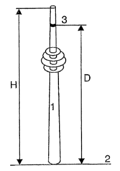
The tower 1 shown in Fig. 1 has a height H of at least
50m, preferably about 90m to 320m. Instead of a tower any
high structure can be used, such as, but not limited to, a
chimney, a radio tower, a skyscraper, or even a zeppelin
hovering at a fixed location. At distance D from the
erection ground 2 there is arranged at least one ring 3 of
antennas, each antenna defining a sector. Distance D should
be in the range of 50m to 450m. It is possible that ring 3
is located in the top of the tower, resulting in a distance
D equal to height H.
In an embodiment according to Fig. 2 two rings of
antennas, an outer ring 4 and an inner ring 5, are
provided. The inner ring 5 has 24 sectors 6 of antennas,
each comprising a 15-degree horizontal angular range. The
outer ring 4 is subdivided into 72 sectors 7, each
comprising a 5-degree horizontal angular range. In general
using only one ring of antennas is possible as well when
using at least 6 antennas defining 6 sectors.
The vertical aperture angle of the inner antennas is 10
degrees covering a distance in the range of lkm to 3.2km at
about 10 degrees tilt. The vertical aperture angle of the
outer antennas is 5 degrees covering a distance in the
range of 3.2km to 6.4km at about 2.5 degrees tilt.
Consequently, each sector 6 or 7 (inside or outside)
covers an area of about 1.33 square km.
CA 02488285 2009-05-21
25890-177
13
In Fig. 3 another high site 1 is shown, which is
located on the erecti,--)n ground 2. Two or more antennas can
be arranged in a concentric ring 3 in an orthogonal plarie
of the longitudinal axis 9 of the high site 1. The antennas
can be connected to the exterior of the high site, they can
be connected to a frame, which is located around the high
site, or any other construction arranging the antennas in
the concentric ring can be used.