Note: Descriptions are shown in the official language in which they were submitted.
CA 02488424 2004-11-24
SHROUDED FLEXIBLE PACKAGES
s
Background of the Invention
~0 1. Field of the Invention
The present invention pertains to flexible packages having fastener closures
employing sliders and, in particular, to such packages having a shroud
enclosure for
the slider.
is
2. Description of the Related Art
Consumers purchasing bulk quantities of food products have come to rely
upon the recloseable packaging. One of the most popular means of providing
2o reclosability is to employ zippers of various types, particularly zippers
which are
compatible with flexible packages of plastic film construction. Manufacturers
of food
products and other commodities are concerned with filling the contents of a
flexible
package as quickly and as economically as possible, utilizing mass production
forming, filling and sealing techniques. Shrouded packages add a level of
complexity
2s to the packaging efforts, in that the package construction must be
carefully
coordinated with manufacture and assembly of the fastener components. Other
difficulties arise when the consumer opens the shrouded package for the first
time.
As an initial step, the consumer must gain access to the fastener components,
particularly the slider. This requires the shroud, which usually spans the
entire width
30 of the fastener system, to be entirely removed. It is generally preferred
that the
shroud be removed in a simple tearing operation, without requiring tools or
comaterial
strips. It is important that the tearing be made reliable and that it leave
clean edges on
the flexible package, once removed.
CA 02488424 2004-11-24
Summary of the Invention
One embodiment of the invention relates to a recloseable, flexible package in
which opposed front and rear panels are joined to first and second
interlockable
fastener tracks. A slider is movable along the fastener tracks for closing and
opening.
A shroud covers the slider in at least a portion of the fastener tracks and a
continuous
weakening portion in the shroud; generally coextensive with the fastener
tracks,
severs the upper portion of the package, i.e., the shroud, for removal. The
weakening
portion is preferably formed as a laser score line. The score line is located
adjacent a
side seal of the package at a point above the fastener tracks and then crosses
over the
l0 fastener tracks, continuing along a line spaced from and generally below
the fastener
tracks. The side seal may contain a slit or cutout communicating with the
laser score
line to provide assistance for the initial tearing effort. The score line
preferably is
non-linear overall, but may have either linear or curved sections.
i5 Brief Description of the Drawings
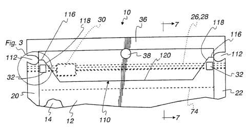
Fig. 1 is a fragmentary front elevational view of a flexible package in
accordance with the present invention;
Fig. 2 is a fragmentary exploded perspective view showing removal of the
shroud;
2o Fig. 3 is a fragmentary view of Fig. 1, taking on an enlarged scale;
Fig. 4 is a rear elevational view of the package;
Fig. 5 is a fragmentary front elevational view of an alternative embodiment of
a flexible package according to principles of the present invention;
Fig. 6 is a fragmentary front elevational view of another embodiment of a
25 flexible package according to principles of the present invention;
Fig. 7 is a cross-sectional view taken along the line 7-7of Fig. 1; and
Fig. 8 is a cross-sectional view similar to that of Fig. 7 but showing an
alternative construction of the fastener tracks.
3o Detailed Description of the Preferred Embodiments
Referring now to the drawings and initially to Figs. 1-4, a flexible package
is
generally indicated at 10. The terms "package" and "bag" are used
interchangeably
and are not intended to refer to any relative size of the finished item.
Flexible
2
CA 02488424 2004-11-24
package 10 preferably takes the form of a plastic bag having front and back
panels 12,
14 joined together at the left end by a side or marginal seal 20 and at the
right end by
a side or marginal seal 22. The side seals 20, 22 are preferably of
conventional
conduction heat-seal construction, having a generally constant width
throughout. If
desired, the side seals can be made to have a width which varies along their
length
(see Fig. 6). The bottom of package 10 can take on virtually any conventional
construction known today. For example, the front and rear panels can be sealed
with
a fin or marginal seal as shown at the bottom of Fig. 7 or the bottom of the
package
can be formed with a dead fold as can be seen at the bottom of Fig. 8. If
desired, an
adjusted bottom construction can also be employed.
The upper end of flexible package 10 features a recloseable opening including
a slide fastener arrangement with fastener tracks 26, 28 and a slider 30, all
preferably
of polyolefin material. The slider 30 is slidable along the fastener tracks,
causing the
fastener tracks to interlock or mate for closure of the flexible package and
to unmate
or separate to open the flexible package for access to contents in the package
interior.
As illustrated in Figs. 7 and 8, the fastener tracks can be made in a variety
of different
forms, as will be described herein. Generally, it is preferred that the
specific tracks be
installed in a manner which provides a rupturable or peelable seal which must
be
breached upon initial entry to the package interior.
The panels 12, 14 of plastic sheet material can be of a homogeneous or single
material type such as polyolefrn materials including polyethylene and
polypropylene.
Preferably the plastic sheets comprise a laminate assembly of several
different
material types, as is known in the art to provide a barrier to moisture as
well as certain
gases, such as oxygen or inert fillers of the types used with food products.
Other
types of laminate films, such as those known in the art to preserve food
freshness,
may also be employed. Where the contents of the flexible package are not
perishable,
or where other considerations may dictate, the panels 12, 14 can be
constructed
without regard to gas or vapor barrier properties.
Refernng to Fig. l, when slider 30 is moved to the right, the fastener tracks
26, 28 are unlocked, opening the flexible package 10 and allowing the user
access to
either the package interior or to a rupturable peelable seal providing a final
barrier to
the package interior and the products contained therein. End stops 32 are
formed in
the fastener tracks to hold slider 30 captive. Preferably, end stop portions
32 are
CA 02488424 2004-11-24
spaced from the side or marginal seals 20, 22 to prevent distortion of the
stops arising
from heating as the side seals are formed. Other arrangements are, however,
contemplated by the present invention, as will be explained below. The upper
end of
package 10 may be formed with a dead fold or with a preferred marginal or fin
seal 36
shown in the figures. A peg hole 38 is formed at the upper end of package 10
and
may intrude into the upper seal 36, if desired.
Turning now to Fig. 7, the bottom ends of panels 12, 14 of package 10 are
sealed with a fin seal or marginal seal 42. In a preferred embodiment, as
illustrated,
panels 12, 14 extend the full height of package 10 between top and bottom
seals 36,
42. The upper portions of panels 12, 14 indicated by the reference numeral 46
together comprise a shroud portion covering the fastener tracks 26, 28. Fig. 2
shows
the shroud portion 46 separated from the remaining portion 102 of bag 10,
i.e., the
package sidewalls, so as to expose the slider 30 and the fastener tracks 26,
28.
Referring again to Fig. 7, flanges 50, 52 depend from fastener tracks 26, 28.
Preferably, the flanges have a double layer thickness with both layers of the
flange
including a sealant material. The longer flange 50 continued upwardly from
bottom
portion 54 to form an opposed wall portion 56. Bottom portion 54 is preferably
formed as a rupturable reverse fold. As shown in Fig. 7, the opposed wall 56
is
arranged in line with the shorter flange 52, with flange 52 and flange portion
56
2o having adjacent spaced apart free ends. The reverse fold of bottom portion
54 is
preferably maintained by a tack seal 58. The bottom portion 54 as illustrated,
has a
reduced thickness with material being displaced into a pair of ridges 62. It
is
generally preferred that the bottom portion 54 be sufficiently weakened so as
to be
readily opened by a consumer in accessing the package interior after removing
the
shroud and operating the slider members so as to unmate the fastener tracks.
As
desired, the reverse fold weakened area can be replaced by a conventional peel
seal
design.
As shown in Fig. 7, fusion seals 70, 72 and 74 are employed to join the
fastener track assembly to panels 12, 14. Fusion seal 74 joins a pre-seal
portion of the
longer flange 50 to panel 12. Fusion seal 70 joins the lower portion of
shorter flange
52 to panel 14 while fusion seal 72 joins wall portion 56 to a portion of
panel 14
spaced from fusion seal 70.
4
CA 02488424 2004-11-24
Turning now to Fig. 8, an alternative arrangement of a flexible package 80 is
shown. Package 80 is substantially identical to package 10 except for the
construction
of the zipper track assembly and its joinder to panels 12, 14 and the use of a
dead fold
84 which joins together the bottom ends of panels 12, 14. The fastener tracks
26, 28
have tail portions 86 joined to flanges 90, 92. A peelable seal 94 joins the
bottom
ends of flanges 90, 92, but must be breached by the consumer as a final step
prior to
gaining access to the interior of package 80.
If desired, other fastener track arrangements different from those described
above may be employed. As mentioned, the peelable seal features or other
rupturable
l0 seal internal to the package can be omitted, if desired, as when the
package is
employed for non-perishable items.
It is important that a consumer or other end user of the flexible package be
able to quickly gain access to the package interior without requiring special
tools or
by following detailed directions. Opening of the package 10 should be
intuitive and
the removal of the shroud should leave clean edges. The present invention
contemplates removal of the shroud by tearing the panel material from which
the
upper shroud portion (e.g., see reference numeral 46 in Fig. 7) and the
remaining side
wall portions (see reference numeral 2 in Fig. 7) are formed.
Turning now to Figs. 1-4 and 7, a two-dimensional (i.e., non-linear) score
line
110 extends from one side of package 10 to the other. As shown in Fig. 1, it
is
generally preferred that score line 110 extends up to side or marginal seals
20, 22. In
a preferred embodiment, curved cutout portions 112 remove material from the
side
seats 20, 22. As shown, cutout portions 112 are preferably continuously curved
with
the ends of score line 110 intercepting the innermost edge of the cutout,
adjacent the
inner edge the side or marginal seals. Score line 110 includes initially
horizontal
portions of relatively small length, extending but generally parallel to the
fastener
tracks. The initial portion is indicated by reference numeral 116, located at
a point
above the fastener tracks and above the stop 32 for slider 30. Score line 110
further
includes a portion 118 inwardly and downwardly directed, crossing over the
fastener
3o tracks 26, 28 thus to meet with a medial portion 120 spaced below and
oriented
generally parallel to the fastener tracks. If desired, score line 110 could be
formed of
discreet segments but preferably is continuously formed without interruption,
from
end to end. Knives, dies or other tooling can be used to form the score line
110, as is
CA 02488424 2004-11-24
known in the art, but preferably score line 110 is formed using a laser energy
source,
which has been found to provide superior tear direction and clean edges once
the
shroud is separated.
Referring to Fig. 2, it will be seen that portions of the package panels are
left
in place covering the end stops 32. With this desired positioning of the score
line 110,
the triangular portions of the package panels underneath the score line parts
116, 118
may be relied upon to hold slider 30 captive on fastener tracks 26, 28, thus
allowing
the elimination of end stops 32. It will be noted in this regard that the
portions of the
package panels interfering with the fastener tracks after shroud removal
extend above
to the fastener tracks by a substantial distance, further ensuring that the
slider will
remain captive on the fastener tracks after access to the package interior is
gained. If
desired, the application tooling used to form side seals 20, 22 can be formed
to
displace fastener track material within the side seal area and vertical
directions below
and especially above the fastener tracks to back up the panel material
remaining .
above and below the ends of the fastener tracks after shroud removal.
As can be seen, for example, in Fig. 2, the central portion 120 of laser score
line 110 is spaced a substantial distance below the fastener tracks. The lower
most
portion of the laser score line is still located well above the peel seal
features of the
package, which are provided utilizing flanges of the fastener track assembly.
Thus,
due to this first aspect, package integrity is preserved. As a second feature
preserving
package integrity, a continuous unbroken score line is employed as the
preferred form
of weakness which allows separation of the shroud. Thus, the shroud enclosing
the
fastener tracks remains unbroken, awaiting customer removal of the shroud.
As mentioned before, the line of weakness provided for separating the shroud
is preferably formed using a laser energy source to provide a two-dimensional,
that is,
non-linear score line. Use of a laser energy source, particularly when forming
a non-
linear score line, results in improved reliability of the tearing separation
of the shroud
portion. Once initiated at the oval-cutouts 112, tearing extends along a
relatively
short segment 116 before being directed generally at a 45o downward angle to
the
3o central portion 120. The use of a laser energy source to form the score
line and the
shape of the score line described above, has been found to result in
surprisingly
reliable uniform tearing during shroud removal even when the package panels
are of
relatively thin and stretchable material, and even though the score line
formed in one
6
CA 02488424 2004-11-24
package panel may not be aligned precisely with the score line formed in the
opposing
package panel. This latter feature is important when a user grasps both sides
of the
shroud together in a tearing operation, thus applying at a single point,
tension to
misaligned panel upper portions.
In one commercial embodiment, flexible package 10 comprises a plastic bag
having a width of approximately 6.5 inches from side edge to side edge and a
total
overall height of approximately 10.75 inches. The fastener tracks 26, 28 have
a
height of approximately 4mm, while the side seals have a width ranging between
2
and Smm. The cutout 112 has a generally oval shape, as illustrated, with a six
to millimeter vertical dimension. The initial segment of the score line 116
has a length
of approximately IOmm and the converging section of the score line 118 forms
an
angle of approximately 45o to the top and side marginal edges of the package.
Refernng now to Fig. 6, an alternative embodiment of a package according to
principles of the present invention is generally indicated at 200. Package 200
has
t5 features identical to the package described above with reference to Fig. 1,
except for
peg hole 202 formed entirely within top margin 36, which includes a bulge in
the area
of the peg hole. As a second difference, the score line 206 is continuously
curved and
extends across the side seal 22. As can be seen in Fig. 6, side seal 22 has a
non-
constant width, being narrower in its upper portion and wider at its lower
portion,
2o with a width-wise transition located generally at the central portion 206a
of score line
206. As mentioned, the score line 206 crosses side seal 22 and, in the
preferred
embodiment, is shown as a relatively short, generally horizontal segment 206b.
The
score line includes curved transitions on either side of a convergent sloping
segment
206c.
25 As shown in Fig. 6, fastener tracks 26, 28 are deformed, being enlarged in
the
vicinity of side seal 22. The deformation comprises slider stop 32 and, as
shown in
Fig. 6, the slider stop displaces fastener track material in a generally
upward direction
with a sloping portion generally underneath the sloping portion 206c of score
line 206
and a generally horizontal portion in the region of overlap with side seal 22.
As with
3o the preceding embodiments, it is generally preferred that panel material
210 be left
covering the fastener tracks and extending above the end of the fastener
tracks,
adjacent side seal 22, after the shroud is removed. The covering portion 210
further
assists in maintaining slider 30 captive on fastener tracks 26, 28 and can
replace the
CA 02488424 2004-11-24
stop 32, if desired, for this purpose provided that the side seal 22 include
fusion of
panels 12, 14 above the stops. As with the preceding embodiments, it is
generally
preferred that score line 206 be formed using a laser energy source.
Only one side of package 200 is shown in Fig. 6. It is generally preferred
that
that portion of the score line at the right-hand side of the package (not
visible in Fig.
6) comprises a mirror image of the opposing side, as illustrated. However, if
desired,
the end portions of the score lines (i.e., those portions adjacent the side
seals of the
package) need not be identical, i.e., need not comprise minor images of one
another.
If desired, a notch or cutout can be formed, either in a portion of side seal
22, or the
1o entirety thereof, adjacent score line segment 206b. As shown in Fig. 6,
score line 206
is continuously curved, i.e., does not contain angled portions, as illustrated
in Fig. 1,
for example. If desired, the score line can contain angled portions. However,
it is
generally preferred that the score line be continuous from one side of the
package to
the other.
Referring now to Fig. 5, a flexible package 300 is generally identical to the
flexible package 10 described above, except that the cutout 302 formed in side
seal 20
is different from the cutout 112 formed in side seal 22. In Fig. 5, slider 30
is shown in
the fully opened position. Preferably, package 300 includes a peel seal
located below
the fastener tracks and thus, in light of this feature and the preserved
integrity of the
2o shroud portion, the fastener tracks can be shipped in an open position, if
desired.
Generally, however, it is preferred that the fastener tracks be fully mated
and that
slider 30 be located adjacent side seal 22, as shown for example in Fig. 1.
Cutout
302, can be seen is continuously curved, but has a smaller size than cutout
112.
Accordingly, score line 110 is extended across a portion of side seal 20 so as
to
communicate with cutout 302, ensuring continuous control of the tearing
operation,
should the consumer initiate tearing at side seal 20.
The drawings and the foregoing descriptions are not intended to represent the
only forms of the invention in regard to the details of its construction and
manner of
operation. Changes in form and in the proportion of parts, as well as the
substitution
of equivalents, are contemplated as circumstances may suggest or render
expedient;
and although specific terms have been employed, they are intended in a generic
and
descriptive sense only and not for the purposes of limitation, the scope of
the
invention being delineated by the following claims.