Note: Descriptions are shown in the official language in which they were submitted.
CA 02488474 2004-11-26
VARIABLE TEST OBJECT AND HOLDER FOR VARIABLE TEST OBJECTS
DESCRIPTION
Field of the invention
The invention relates to a variable test object, which consists of at least
two targets and a
connecting element, and a holder for such variable test objects.
State of the art
For the monitoring of co-ordinate measurement machines and production devices,
measurements on test objects are required which acquire the main deviations of
the
measurement machine or the production device. As mechanical comparative
standards,
such test objects represent an economical alternative to measuring comparative
standards, such as for example interferometers. Although measurements with
interferometers supply reliable information on the precision of the inspected
machines,
such a method in practice is very time consuming, so that the monitoring
intervals are
often chosen to be very long, e.g. annual. Modern machine tools and industrial
robots
operate in tight tolerance ranges and sometimes exhibit drift characteristics
so that more
frequent checking is necessary. With mechanical test objects additional
inspections at
shorter time intervals are possible also under economical viewpoints.
Depending on the field of application, various requirements are placed on test
objects. In
particular they should provide reliable measurement results within the scope
of standard
measurement conditions, i.e. at a temperature of -20 C to +70 C and a relative
humidity
of 0% to 100%, in order that they can be employed under various ambient
conditions.
Furthermore, the dimensions to be measured are sometimes very different. With
large
equipment to be measured they may extend into the range of some metres to over
ten
metres. Another viewpoint is the flexibility and the mobility of the test
object which is why a
large test object should preferably be able to be disassembled for transport
and should be
as light as possible, wherein however the accuracy of the measurements on the
test
object should be ensured.
CA 02488474 2004-11-26
2
A mechanical test object is described in DE 199 15 012 Al. It consists of four
probe form
elements and six connecting elements which are combined in a tetrahedral
shape, so that
the probe form elements are located at the corners of the tetrahedron. Each
connecting
element is located between two probe form elements. The materials of this test
object are
chosen such that a linear thermal expansion coefficient from probing point to
probing point
arises which is essentially equal to zero. Here, due to the design, the
connecting elements
are equally long in order to provide a self-supporting structure through the
special shape
of the tetrahedron, maintaining the probe form elements in well defined
positions. This
type of test object can be disassembled, the probe form elements are made of
steel or
glass ceramics and the connecting elements are of a light material, i.e.
carbon-fibre
reinforced plastic (CFRP), whereby good transportability is ensured. In one
embodiment
the releasable connections of the probe form elements to the connecting
elements are
based on magnetic forces.
The parts of the tetrahedron can however also be combined in that a number of
connecting elements are arranged one behind the other, with in each case a
probe form
element between them and one at each of the two ends of the linear
arrangement,
forming a ball bar. Here, up to three additional probe form elements are
optionally
employed. The probe form elements may have various designs depending on the
field of
application, e.g. in the form of a ball or a different shape. Then probing
points at intervals
of integer multiples of the distance between two adjacent probe form elements
are
available, wherein the minimum distance is determined by the length of one of
the
connecting elements of the same length and the maximum length is six times the
minimum distance.
To incorporate a ball bar thus formed into the measurement volume a holder is
needed for
reasons of stability and adjustment. According to the state of the art, this
holder consists
in this case of single seats onto which the probe form elements are placed,
wherein
however an adequate linear alignment of the ball bar must be achieved with low
deviations in alignment.
The probing of the probe form elements occurs through tactile contact, i.e.
they are for
example probed with measuring styli through direct contact. However, amongst
the state
of the art are also elements measured by light. Generally, here a measurable
element of a
test object is designated a target. For measurements with tactile systems,
chromium or
CA 02488474 2004-11-26
3
stainless steel balls are, for example, used and the determination of the
centre point of the
ball occurs via a bali measurement. Also so-called reset targets can be
measured by
tactile systems, wherein the centre point of the ball is obtained using a cone
in which a
small ball with a defined diameter is placed so that the centre point of the
target can be
directly probed via a simple point measurement. If the probing is carried out
using light,
so-called retro-targets or theodolite targets are employed, for example, for
measurements
with photogrammetric and other optical systems. Finally, prisms can also be
used for
measurements with a laser tracker as target.
Other ball bars are also known from the state of the art, wherein the probe
form elements
are balls consisting of ceramic held on a carrier body at uniform distances by
leaf-spring
elements firmly joined to the carrier body. The exact distance between the
balls is
provided by distance tubes of steel which are clamped between the balls.
From the state of the art a holder for linear ball bars with fixed ball
mountings at constant
ball distances and the application of independent single seats is known.
Other known test objects, which cover two or three spatial dimensions, are
designed in
the form of a ball plate or ball cuboid, wherein the distances between the
balls are
permanently specified.
The test objects known from the state of the art have either the disadvantage
of being
inflexible due to the given ball distances or of being unusable due to a
holder that is
unsuitable for many purposes.
With the holder with fixed ball mountings it is disadvantageous that the
distances of the
balls are defined and constant due to the fixed position of the ball holders
on the carrier
body. Adaptation of the ball distances to the relevant measurement
requirements is
therefore not possible.
If the balls and bars are clamped, then stresses arise which can impair the
measurement
result, which is a disadvantage. Furthermore, a poorer temperature neutrality
when using
steel as the material for the distance tubes is also disadvantageous.
CA 02488474 2004-11-26
4
If a ball bar is placed on single seats, then adequate linear alignment of the
ball bar must
be ensured in order to achieve a low alignment error, which can only be
obtained
conditionally and with difficulty using seats which have to be adjusted
independently of
one another and which therefore is disadvantageous.
From the state of the art, as described above, only test objects are known
which exhibit
fixed distances between the targets. Here, the distances are already defined
by the
construction. In the case of ball bars with variable lengths of the connecting
elements,
such a construction is either unstable and therefore is not easily used or
difficult to align
and can only be positioned as required in the measurement volume with a great
deal of
adjustment.
Variable test objects, which cover one or more dimensions, and an associated
stable
holder for such test objects which can be arranged flexibly are not known from
the state of
the art. From the state of the art only one holder for linear ball bars with
fixed ball
mountings at constant ball distances or the use of independent single seats is
known.
Description of the invention
In view of the disadvantages of the state of the art, the basis of the
invention is the
problem of providing a variable test object and an associated holder for
variable test
objects, which are matched such that such a variable test object can be held
by the
holder.
On one hand a variable test object should be provided which can be arranged
flexibly, so
that within the scope of a given set of targets and connecting elements, which
at least
partially facilitate different distances between the targets (in other words,
which do not all
necessarily give rise to the same target distances), various test objects can
be combined
and up to three dimensions acquired.
On the other hand a holder for variable test objects is to be provided, by
which at least
one such test object is held, whereby it should be possible to position test
objects stable in
the measurement volume with variably arranged distances between the targets.
Furthermore, such a holder must ensure that the targets of the test object are
adequately
CA 02488474 2004-11-26
accessible for the measurements, irrespective of whether they are taken by
tactile contact
or with the aid of light.
The previously mentioned problem is solved by a test object according to the
invention,
with at least two targets and at least one connecting element, wherein the
targets and
connecting elements used for the test object can be selected from a given set
of single
targets and single connecting elements and can be combined to form test
objects, and the
targets and connecting elements are equipped such that they are held together
by
magnetic forces such that the test object is sufficiently stable to be held by
the holder
according to the invention, and that, due to a suitable choice of material of
the targets and
connecting elements, the thermally induced change in the distance between the
targets of
the test object is maintained within the scope of the measurement tolerances.
In addition, the invention comprises a holder for test objects, which are
composed of at
least two targets and at least one connecting element, with at least one
carrier, at least
one guide, which is arranged on or / and in the at least one carrier, and
seats for the
targets of at least one test object, wherein at least one seat can be moved
along the at
least one guide so that adaptation of the position of at least one movable
seat to the
position of a target of the test object is possible, wherein the test object
can be held by the
holder after the adaptation.
A test object according to the invention is characterised in that it is
suitable for use in the
holder according to the invention and facilitates variable target distances,
whereby the
holder according to the invention can be adapted to the relevant test object
and at the
same time facilitates a stable position and flexible usage of the test object.
Depending on requirements, such a test object according to the invention can
realise
different target distances, it can be adapted to the size of the measurement
volume and
also cover several dimensions. Furthermore, within the scope of the production
tolerances, it has no linear thermal expansion under standard conditions and
therefore
maintains the chosen target distances. The at least partial use of CFRP
material for the
connecting elements also has the advantage of providing a light-weight and
thus easy-to-
use, easily transportable test object which can be securely held by the holder
according to
the invention.
CA 02488474 2004-11-26
6
A holder according to the invention is characterised in that it can hold a
test object
according to the invention, It has the advantage that at least one seat can be
moved along
the at least one guide such that an adaptation of the position of the at least
one movable
seat to the position of a target of the test object is possible, whereby at
least one test
object according to the invention is securely held. Consequently, simple
fitting of the test
object in the measurement volume is possible, while maintaining the test
object stability
and the target distances.
Furthermore, the holder according to the invention is characterised in that
the carrier
consists of a material, the linear thermal expansion coefficient a = oLIL of
which lies in the
range from a= 0 20 um/ Cm, preferably a = 0 10 pm/ Cm and most preferably
a = 0
1 Nm/ Cm. Here, AL is the linear change in pm per C of temperature change per
length L
in m.
Depending on requirements, more than one carrier can be used. For example,
this may
be necessary with a branching of the ball bar mentioned below. Furthermore, it
may be
necessary for one holder to hold more than one test object. For reasons of
stability it may
be advantageous to arrange the seats to be movable through more than one
guide. If the
targets are not just aligned along a straight line, as for example with a ball
bar, then it is
advantageous to arrange at least one further guide on or / and in the carrier,
permitting a
variable positioning of the seats in two or more parallel or / and different
directions.
In the case of the ball bar which is formed from the tetrahedron constituents,
according to
the invention at least different lengths of the connecting elements can be
partially used to
arrange the target distances flexibly and consequently to obtain variable ball
bars. If, for
example, a set of n suitable different lengths of connecting elements and n +
1 targets are
available, then due to corresponding selection and combination of the
connecting
elements a total of n + n=(n + 1)/2 different target distances can be
realised, whereas
with a corresponding set containing the same length of connecting elements,
there are
only n different target distances. Taking as a numerical example six
connecting elements
and seven targets in the relevant sets, then 27 different target distances can
be formed in
the case of the variable lengths of the connecting elements. In the case of
equally long
connecting elements there are only six different target distances, as
mentioned above.
CA 02488474 2004-11-26
7
Other possible variations for a test object on the basis of a ball bar exist
according to the
invention in that a general arrangement is selected, whereby, for example,
using a further
target and two further connecting elements a side branch to a linear ball bar
can also be
formed to cover a second dimension. With a further branch the third dimension
can be
covered. In this way with suitable lengths of connecting elements in the
branches, it is
possible, for example, to represent reproducibly well defined angles between
the targets.
Such branches are however unstable about the axis of the linear ball bar and
must be
appropriately held.
The connecting elements of a variabie test object according to the invention
need not be
restricted to the connection of exactly two targets, but rather they can also
connect
together three or more targets. The possible variations of such a test object
are based on
the different positions of the targets, which are given by the individual
connecting
elements and on the different possible combinations of many connecting
elements, which
are coupled via the targets.
The previously mentioned holder can be developed further as described in the
foliowing.
In a preferred further development several or all supports are movable,
whereby the
positions of several targets become variable. Consequently for example,
variable ball
bars, which consist at least partially of bars of different length and of
targets, can be
composed and held such that the positions of the seats are adapted to the
relevant
positions of the targets.
In another further development at least one of the seats is fixedly joined to
the carrier,
wherein however at least one seat is movable. In this way a test object, for
example which
is composed of at least two targets and at least one selected connecting
element, can be
held in that at least one fixed seat accommodates one of the targets and at
least one
other seat is adapted by displacement to the position of the other target
determined by the
relevant connecting element. With this type of holder it is, for example,
possible to hold
variable ball bars so that at least one target has a fixed position with
respect to the holder.
In another further development the material of which the at least one carrier
consists has
a linear thermal expansion coefficient a= oUL in the range of a= 0 20 iim/
Cm,
preferably a = 0 10 Nm/ Cm, most preferably a= 0 1pm/ Cm.
CA 02488474 2004-11-26
8
Another further development consists in that the material of the at least one
carrier
comprises CFRP material.
Through the use of this type of material in particular linear thermal
expansion coefficients
in the range of a= AL/L = 0 0.1 Nm/ Cm can even be realised. This type of
carrier has
no linear thermal expansion in the range of standard conditions except within
the scope of
the manufacturing tolerances.
In another advantageous further development of the holder according to the
invention, at
least one support is arranged such that at least one target of a test object
is held by
magnetic forces. This has the advantage that the at least one target can be
fitted onto the
support quickly and easily and that it is securely held.
There is another further development in which at least one held test object is
a ball bar
and the holder ensures so little alignment error of the linear alignment of
the target that
the deviation of the distance of any two targets of a ball bar from the
corresponding
distance of the geometrically exact linear alignment is smaller than the
calibration
uncertainty U = 1.5 Nm + 1.5 pm = L/m, wherein L is the distance between two
targets.
The calibration uncertainty includes a constant and a length dependent
component. The
calibration uncertainty of a connecting element, which positions two targets
at a distance
of, for example, two metres from one another, accordingly is 4.5 Nm. In this
version a
sufficiently good linear alignment of the targets is ensured so that the
distances of any two
targets of the ball bar are well known in accordance with the measurement
requirements.
In another further development the at least one carrier consists of single
elements and
these single elements are held together by at least one releasable connection,
such that
reproducibility of the holder is ensured, in particular in that the accuracy
of the distances
of the targets of a held test object after each mounting of the holder is
better than the
calibration uncertainty 1.5 /im + 1.5 Nm = Um. In this embodiment large
holders can be
disassembled for transport and be assembled again such that the measurements
on the
targets of the held test objects are reproducible.
A further advantageous further development is obtained if, due to suitable
materials and
suitable geometries of the constituent parts of the holder, the positions of
the targets of a
CA 02488474 2004-11-26
9
held test object vary at the most within the calibration uncertainty 1.5 pm +
1.5 pm = Um
due to the physical ambient conditions varying within the scope of the
standard
measurement conditions or / and due to mechanical effects with proper use of
the holder
and its constituent parts.
Another advantageous further development is characterised in that the
combination of the
seats exhibits at least one degree of directional freedom, wherein the
relevant degree of
freedom points in the direction of the connecting line of the connected
targets, so that the
targets and the connecting elements are not subject to any stresses. This is,
for example,
facilitated by a combination of point and V-supports. Optionally, a flat seat
can also be
used. This type of arrangement is characterised in that a stress-free setting
up of the test
object can occur and that the test object is also held free of stress. If the
first target, for
example, is placed on a point seat and then the connecting element is coupled
magnetically to the first target, then finally the second target can be
brought on a V-seat
and, free of force, coupled onto the other end of the connecting element. In
this way it is
furthermore possible to add further connecting elements and targets to build
them up on
the holder to form a larger test object, such as for example a ball bar.
Stress-free
branches on a ball bar can then be achieved with flat seats.
In another advantageous further development the holder comprises at least one
mounting
on which the holder can be mounted in the measurement volume. In particular
these
mountings, for example, can be suitable for fitting the holder on one or more
tripods.
The various further developments can be used independently of one another or
combined
suitably with one another.
Further preferred embodiments of the invention are described in the following
with
reference to the drawings.
Brief description of the drawings
Fig. 1 shows a first embodiment of a test object according to the invention
with a holder
according to the invention.
CA 02488474 2007-02-08
Fig. 2 shows a second embodiment of a test object according to the invention
on a holder
according to the invention with a special form of seat.
Fig. 3 illustrates the concept of alignment error in the linear alignment of a
ball bar.
Fig. 4 shows a third embodiment of a test object according to the invention in
the form of a
ball bar with a branch.
Description of the embodiments
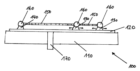
Fig. 1 shows a test object according to the invention on a holder according to
the
invention. In this example the test object is a ball bar with two connecting
elements 150
and three targets 160, which are held together releasably by magnetic forces.
Here, the
connecting elements and targets are selected from a given set in which at
least two
connecting elements of different length are provided, so that different target
distances can
be realised. The holder comprises a carrier 110, which can be disassembled
into single
elements which are held together by a releasable connection 170, as well as a
guide 120
for the seats 130, 140 on which the targets are located. One seat 140 is
fixedly fitted to
the carrier so that the exact position of the target located on it is also
known relative to the
holder. Two seats 130 are movable, so that adaptation of the position of the
seats to the
lengths of the connecting elements and the distances and positions of the
targets they
define is possible. The carrier material comprises CFRP material.
This material was manufactured using Tennax UMS 252624KT"' fibres and resin
with the
DIN designation L 160 as well as hardener with the DIN designation H 163. This
resulted
in a linear thermal expansion coefficient of lal < 0.1 pm/ Cm.
Fig. 2 illustrates an advantageous embodiment of the supports. Here, a target
260 of the
test object rests on a point seat 230 and is thus stabilised in its position.
A further target is
located on a V-seat 240. A connecting element 250 is arranged between the two
targets.
Such an arrangement is characterised in that a stress-free setup of the test
object can
occur and that the test object is held free of stress. If the first target is
placed on the point
support and then the connecting element is magnetically coupled to the first
target, the
second target on the V-seat can be brought up to and coupled to the other end
of the
CA 02488474 2004-11-26
11
connecting element. In this way it is furthermore possible to add further
connecting
elements and targets and to set up a larger test object on the holder.
Fig. 3 illustrates the concept of alignment error in the linear alignment of a
ball bar. Here
as an example, at least an extract of a ball bar is illustrated in which the
target 360c
deviates slightly from the geometrically exact alignment. The perpendicular
distance D of
the target 360c to the alignment line is known as the alignment error. The
question now
has to be put of how large the alignment error D may be as a maximum so that
the
distance L, + L2 of the target 360b and the target 360d reduces to no more
than the
calibration uncertainty U on L,' + L'2, since U also determines the quality of
the ball bar
and the amount of the change of distance should therefore not be greater than
U. The
greatest change occurs when the distance of target 360b to target 360c and the
distance
of target 360c to target 360d are equal. Assuming that this distance is in
each case L = L,
= L2 = 0.5 m, i.e. a distance of target 350b to target 360d of 2L = 1 m,
wherein the
calibration uncertainty of the distance of target 360b to target 360d is
approximately U = 3
jim. The relationship 2L - 2L' < U should apply. From the drawing the
relationship D2 + L'2
= L2 is given directly producing L%L =v/(1 - D2/L2) - 1- D2/2L2, so that the
maximum
alignment error is given by D=-vl(2L(L - L')) ~v/(L = U). In the given
numerical example D
<_ 1.73 mm must be maintained over a length of one meter so that the change of
the target
distance between target 360b and target 360d is at the most equal to the
calibration
uncertainty. This accuracy can also be achieved reproducibly with holders
which can be
disassembled. Since the calibration uncertainty and therefore also the maximum
alignment error increases proportionally with the length, i.e. both change in
a constant
relationship to one another, an adequate accuracy can also be achieved even
with
substantially greater test object and holder dimensions.
In Fig. 4 a linear ball bar with a branch is shown. Such a branch is unstable
with regard to
strains about the axis of linear alignment of the ball bar and must therefore
be stabilised
by a holder according to the invention. Through suitable choice of the
respective lengths
of the connecting elements, the angle between the connecting straight lines of
the targets
in the branch triangle can be set differently. For example, with a side ratio
of a:b:c of 3:4:5
the angle between a and b is a right angle. This also always applies when az +
b2 = c2. If
also b = c/2, then the angle between a and c is equal to 30 and the angle
between b and
c is 60 . Depending on requirements, any angular check and in particular a
right angle
check can be carried out. In the simplest case the ball bar itself can consist
of just one
CA 02488474 2004-11-26
12
connecting element and two targets, whereby the fitting of a branch enables
the creation
of a triangular test object. Apart from the linear alignment of the ball bar,
a branch of a ball
bar covers a second direction and further directions can be covered by adding
further
branches. Through such an arrangement, for example, long measurement volumes
with a
preferred direction can also be measured three dimensionally with a test
object adapted to
the requirements.