Note: Descriptions are shown in the official language in which they were submitted.
CA 02488780 2004-12-02
INK CARTRIDGE REFILLING PROCESS
This invention relates to a process and system for refilling printer ink
cartridges.
Inkjet printers have gained popularity among computer users in view of their
low initial
cost and versatility. They also produce letter and graphic prints with high
quality. The ink
required by printing is provided by ink cartridges mounted to the print head
of the printer. Ink is
held in a carrier material such as foam fiber located within a cartridge,
which is saturated with
the ink. The printer extracts the ink from the cartridge by vacuum pressure
and delivers it to the
print head. Inkjet printers consume printing ink at a fast rate particularly
when printing graphics
and photographic pictures. As an ink cartridge only holds a limited amount of
ink, the cartridges
would require replacing frequently. Therefore, the cost of operating an inkjet
printer is high with
the necessity of having to replace the ink cartridges frequently. Furthermore,
the spent cartridges
are discarded in the garbage which contributes to the contamination of the
natural environment.
In order to alleviate the above problems, the users of inkjet printers seek to
refill the consumed
cartridges rather than replacing them with new cartridges so as to reduce the
operating cost as
well as the unnecessary discarding of the used cartridges. However, when the
printer can no
longer extract ink from an ink cartridge, there is actually still a trace of
ink remaining within the
cartridge. Such small amount of ink remnant would quickly become dry up to
blockage at the
cartridge nozzle and hardening of the carrier material particularly adjacent
to the nozzle. When
fresh ink is injected into the cartridge for refilling it under such
condition, the harden Garner
material would loose the required physical characteristic for holding the ink
and delivering it to
the print head under vacuum. Furthermore, the dry up remnant of ink at the
nozzle also form
blockage to impede the flow of ink out of the cartridge.
-1-
CA 02488780 2004-12-02
For the above reason, it has been problematic in the refilling of ink
cartridges in that the
nozzle of the cartridge without resolving the above problems. The blockage at
the nozzle may be
removed by cleaning the nozzle external surface with water if the cartridge is
to be refilled as
soon as the ink has been consumed. However, cleaning the nozzle externally
often does not
eliminate the blockage within the opening of the nozzle particularly when the
cartridge has been
removed from the printer for some time without refill it immediately. Also, it
does not eliminate
the hardening of the carrier material in the cartridge. Thus, the refilled
cartridge either does not
function or will only function inefficiently. Furthermore, the wiping
operation would often
destroy the physical structure of the nozzle.
Attempts have been made to remove the internal ink remnant from the cartridge
by
injecting hot water into the cartridge through the nozzle. However, since the
openings of the
nozzle of the cartridge are very small, such process is rather messy and
unsatisfactory as very
little amount of hot water would penetrate into the cartridge.
It is a principal object of the present invention to provide a process of
refilling an inkjet
printer cartridge such that it is clog-free and will function as efficiently
as a new cartridge.
It is another object of the present invention to provide a process of removing
clogging ink
remnant completely from a consumed ink cartridge.
It is another object of the present invention to provide a process of cleaning
the ink
carrying medium within a consumed ink cartridge to revive its ink retaining
characteristic.
It is yet another object of the present invention to provide a system of
refilling an ink
cartridge having a high ink delivery characteristic.
Other objects and advantages of the present invention will become apparent
from the
-2-
CA 02488780 2004-12-02
following detailed description of the preferred embodiments thereof in
connection with the
accompanying drawings in which
Figure 1 is an enlarged front and bottom perspective elevation view of an
inkjet cartridge
with a portion of the enclosure removed to show the ink carrying medium
located therein.
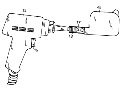
Figure 2 is a perspective side elevation view of the system for cleaning the
cartridge for
remnant ink therein prior to refilling with ink according to the present
invention with the steam
guard tube shown in partial cross section.
With reference to the drawings, an inkjet cartridge 10 has a casing 11 having
a nozzle 12.
Ink holding medium 13 such as foam fiber or similar material is commonly
located within the
casing 11. The medium 13 is saturated with ink when the cartridge is filled
and it ensures that ink
will be delivered to the print head of the printer satisfactorily. A pattern
of electrical contacts 14
is provided on the casing 11 for actuating the ink delivery control system
when the cartridge is
inserted into the printer. When the ink is depleted in the cartridge, it must
be replaced or refilled.
Although an ink cartridge can no longer deliver ink to the print head for the
printing operation,
1 S some ink actually still remain in the cartridge. Such remnant ink often
forms blockage of the
cartridge nozzle as well as hardening of the carrier medium 13 in the portion
adjacent to the
cartridge nozzle particularly if the cartridge is not refilled immediately.
The harden carrier
medium will eventually loose its capability of holding ink even when the
cartridge is refilled and
ink will no longer be delivered to the print head satisfactorily. Thus, in
refilling the cartridge, the
nozzle and the ink retaining foam must be thoroughly cleaned in order that the
refilled cartridge
would operate satisfactorily.
According to the present invention, prior to refilling the consumed ink
cartridge, it is first
-3-
CA 02488780 2004-12-02
cleaned by injecting short bursts of steam with a steam pressure of from S to
45 psi with a
temperature of about 100°C through the nozzle 12. The steam may be
provided with a handheld
steam gun 15 having a manually operable trigger 16. The gun 15 is connected to
a steam
generator (not shown). This operation may be carried out quickly and easily
with relatively small
ink cartridges since the steam would breakdown any dry ink blockage formed at
the nozzle and
penetrate into the cartridge to clean the carrier medium so a.s to return it
to its original physically
characteristic of ink retention. A suction vacuum device similar to the gun 1
S may then be
applied at the nozzle to extract the cleaning steam water from the cartridge
with a suction
vacuum pressure of about 20 to 29 Hg. For relatively larger ink cartridges, in
order to assure the
penetration of the steam into the cartridge, a high temperature relatively
soft silicone tube 17 is
mounted over the steam nozzle 18 of the gun. The end of the soft silicone tube
17 is held in
contact with the nozzle 12 of the cartridge 10 as best shown in Figure 2 to
serve as a guard to
confine the steam over the area of the nozzle 12 of the cartridge 10. A hand
operated steam gun
12 is shown as an example, it can be appreciated by those skilled in the art
that the cartridge 10
may be mounted onto a steam generating device having silicone tube aligned in
contact with the
cartridge nozzle such that the steam may be injected into the cartridge by
operating the steam
generator. Steam under the desirable pressure will effectively be injected
into the cartridge
through the nozzle 12 to dissolve the remnant dry up ink from the nozzle as
well as from the
carrier medium. The entire operation may be carried out quickly without
causing the dissolved
ink and water from splashing over the cleaning station. The operation may be
repeated until the
ink remnant is completely eliminated from the cartridge.
Since the steam is applied to the cartridge in very short intervals, it would
not cause
-4-
CA 02488780 2004-12-02
deterioration of the ink carrier medium or the physical integrity of the
nozzle structure since the
nozzle is not touch physically in the entire operation.
Once the cartridge has been completely cleaned, it may then be refilled by
temporarily
blocking the nozzle 12 and then injecting the ink into the cartridge under
pressure through a
filling opening formed in a selected location of the casing 11. Commonly, the
filling is carried
out with an opening formed at a location opposite to the nozzle 12 so as to
ensure the entire ink
carrier medium 13 is saturated with the ink in the filling operation.
While the present invention has been shown and described in the preferred
embodiments
thereof, it will be apparent that various modifications can be made therein
without departing
from the spirit or essential attributes thereof, and it is desired therefore
that only such limitations
be placed thereon as are imposed by the appended claims.
20
-5-