Note: Descriptions are shown in the official language in which they were submitted.
CA 02488874 2004-12-07
WO 2004/018878 PCT/BE2003/000129
COMPRESSOR WITH CAPACITY CONTROL
The present invention concerns a compressor containing a
compressor element which is provided with a rotor chamber
onto which are connected an inlet pipe and an outlet pipe,
a reservoir in the outlet pipe and a pressure regulating
system comprising an inlet valve erected in the inlet pipe,
a piston which is connected to the inlet valve and which
can be moved in a cylinder, a bridge bridging said inlet
valve and in which, between the inlet pipe and the rotor
chamber, are successively erected a gas stream limiter and
a non-return valve which only admits gas into the rotor
chamber, and a gas pipe connecting the reservoir to the
part of the bridge situated between the gas stream limiter
and the non-return valve, and a relief valve erected in
said gas pipe.
Depending on certain parameters such as operating pressure,
temperature, leakages, delivery or the like, or depending
on a specific compressed air network and the length of the
pipes, or also, depending on the type of application or the
like, a certain type of compressor element will have to be
selected which has to meet the total consumption under the
worst conditions.
In reality, however, there will be variations in certain of
the above-mentioned parameters. When the compressed air
consumption is lower than the production, the pressure in
the pipes will rise. When the operational pressure is
CA 02488874 2004-12-07
WO 2004/018878 PCT/BE2003/000129
-2-
reached in the network of pipes, the production of
compressed air will be stopped in order to prevent
unacceptable high pressures being created. After a while,
the pressure in the pipes will reduce again due to
leakages, consumption or the like and, depending on the
application, pressure will have to be built up again in
order to prevent the operational pressure from dropping
under an unacceptable limit.
For compressors with rotors, such as screw-type
compressors, the pressure-regulating system described in
the first paragraph, also called a load and relief system,
is one of the most frequently used regulating systems to
allow for a production of compressed air from 0 to 100%
with a minimum of energy loss.
In the case of such compressors, the variations in the
consumption of compressed air are adjusted by opening and
closing the inlet valve and the pressure' relief in the
reservoir.
As soon as the operational pressure reaches a certain
level, the pressure regulating system makes sure that the
inlet valve of the compressor element is closed. The
supply of inlet air is in this manner reduced to zero
percent, and the compressor element will run idle. The air
supply at the outlet pipe, in particular at the reservoir
which is usually erected in it, is stopped. When the inlet
valve is closed, the pressure regulating system
simultaneously activates a time switch which makes sure
CA 02488874 2004-12-07
WO 2004/018878 PCT/BE2003/000129
-3-
that the drive of the compressor element keeps on working
for a certain period.
If no specific pressure difference occurs after this
period, the pressure regulating system will order the drive
to be stopped. If, however, a pressure difference occurs
after the aforesaid period, the compressor element will
keep on working and the pressure regulating system will
order the inlet valve to be opened again, so that pressure
can be built up again.
When the drive has come to a standstill and the pressure
level in the outlet pipe is too low, the pressure
regulating system will order the compressor element to be
started, whereby the inlet valve is opened.
With known compressors of the above-mentioned type, the
pressure regulating system contains a strong spring, built-
in in the cylinder and pushing on the side of the piston
which is turned towards the inlet valve, while the cylinder
chamber situated on the other side of the piston is
connected to the reservoir via a control line, equipped
with an electromagnetic control valve.
When the rotors are driven at the initial start-up, the
control valve is not excited, and the pressure in the
reservoir is close to the atmospheric pressure. The relief
valve in the gas pipe is open and, under the influence of
the spring on the piston, the inlet valve is closed. Due
to the underpressure created in the rotor chamber, a small
air flow will flow from the inlet pipe through the bridge,
CA 02488874 2004-12-07
WO 2004/018878 PCT/BE2003/000129
-4-
over the gas stream limiter and the non-return valve, to
the rotor chamber, sufficient to provide for an increase of
pressure in the reservoir.
A continuous air flow is created between the bridge, the
rotor chamber, the reservoir and over the pneumatic relief
valve which has been opened by the built-up pressure, and
then back to the bridge. When the drive is ready to run at
full load, the control valve is excited, as a result of
which the relief valve goes back into the closed position,
and the space above the piston in the cylinder is
simultaneously put under pressure, and the spring force is
overcome, such that the inlet valve is opened. The
production of compressed air now amounts to 100%.
When there is more production of compressed air than
demanded, and the set pressure in the reservoir is maximal,
the excitation of the electromagnetic control valve is
stopped, as a result of which this is closed again. The
space above the piston is connected to the atmosphere via
the control valve, and the relief valve is opened again.
As a result, the inlet valve is closed again under the
influence of the spring, and the reservoir is vented via
the relief valve, the gas pipe and the bridge.
After this venting, the pressure is stabilised at the
pressure for idle running, which is sufficient to provide
for the injection of lubrication liquid on the rotors. A
small amount of air bridges the inlet valve and is sucked
into the rotor chamber via the bridge and the non-return
valve. The production of compressed air is reduced to a
CA 02488874 2007-03-28
-5-
minimum and the compressor turns without producing
anything.
As there is a strong spring in the inlet valve, special
precautions have to be taken. The mounting and dismounting
of the inlet valve is not without any danger because of
said spring. Because of the spring, the inlet valve is
also relatively expensive_ In order to be able to relieve
the spring pressure of the inlet valve, an expensive
electromagnetic control valve with a large passage diameter
is required.
When the relief valve and the inlet valve are controlled
simultaneously, malfunctions sometimes occur.
The invention aims a compressor which does not have the
above-mentioned disadvantages and which is thus relatively
inexpensive, allows for an easy mounting and dismounting of
the inlet valve and allows for a reliable control of the
inlet valve.
According to the invention, this aim is reached in that the
piston is a double-acting piston which divides the cylinder
in two closed cylinder chambers, in that the cylinder
chamber, on the side turned away from the inlet valve, is
connected to a part of the rotor chamber situated near the
inlet valve via a pipe, and in that, on the other side of
the piston, the cylinder chamber is connected to a part of
the rotor chamber situated near the inlet valve and to the
non-return valve via another pipe.
CA 02488874 2004-12-07
WO 2004/018878 PCT/BE2003/000129
-6-
Thus, there is no action of a spring on the piston anymore.
The pipe connecting the cylinder chamber on the side which
is turned away from the inlet valve to a part of the rotor
chamber situated near the inlet valve may as such form the
connection between the piston and the inlet valve, and it
may for example consist of a stem provided with a duct over
its entire length.
The relief valve may then, as in the known pressure
regulating systems, be a pneumatic valve which is
controlled by a pipe connected directly to the reservoir, a
control line having a preferably electromagnetic control
valve in it which is also connected to said reservoir, and
a spring.
In order to better explain the characteristics of the
invention, the following preferred embodiment of a
compressor according to the invention is described as an
example only without being limitative in any way, with
reference to the accompanying drawings, in which:
figure 1 schematically represents a compressor
according to the invention;
figure 2 schematically represents the pressure
regulating system of the compressor from figure 1
during the start-up;
figure 3 schematically represents the pressure
regulating system of the compressor from figure 1, but
when running idle;
CA 02488874 2004-12-07
WO 2004/018878 PCT/BE2003/000129
-7-
figure 4 represents a section of a practical
embodiment of a part of the pressure regulating system
from figures 2 and 3.
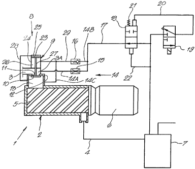
The compressor which is schematically represented in figure
1 is a screw-type compressor which mainly comprises a
compressor element 1 which is provided with a rotor chamber
2 onto which are connected an inlet pipe 3 on the one hand
and an outlet pipe 4 on the other hand, and in which are
erected two screw rotors 5 working in conjunction which are
driven by a motor 6, a reservoir 7 which is erected in the
outlet pipe and a pressure regulating system 8.
As is also represented in the figures 2 and 3, the pressure
regulating system 8 has an inlet valve 9 with a valve
element 10 which works in conjunction with a valve seat 11
in the valve housing 12.
There where the inlet pipe 3 opens into the rotor chamber
2, the latter forms a protruding inlet chamber 13 in which
the valve element 10 is in the open position.
The inlet valve 9 is bridged by a bridge 14 in which the
inlet valve 3 and the inlet chamber 13 are successively
provided, a gas stream limiter 15 and a non-return valve 16
which only allows a gas stream into the inlet chamber 13.
The part of the bridge 14 situated between the gas stream
limiter 15 and the non-return valve 16 is connected to the
reservoir 7 via a gas pipe 17. In this gas pipe 17 is
CA 02488874 2004-12-07
WO 2004/018878 PCT/BE2003/000129
-8-
erected a pneumatic relief valve 18 having an open position
and a closed position.
The relief valve 18 is controlled by an electromagnetic
control valve 19 in a control line 20 which is connected to
the reservoir 7 or, as represented in figure 1, between
this reservoir 7 and the relief valve 18, to the gas pipe
17 on the one hand, and which is connected to the far end
of the relief valve 18 on the other hand, onto which also
acts a spring 21. On the other far end, which is connected
to the reservoir 7 or the part of the gas pipe 17 situated
between the relief valve 18 and said reservoir 7 via a pipe
22, the pressure acts in the reservoir 7.
In one position, the control valve 19 opens the control
line 20, and in another position, it closes off said.
control line 20 on the side of the reservoir 7, while it
connects the control line to the atmosphere on the side of
the relief valve 18.
The pressure regulating system 8 further comprises a
double-acting piston 23 which can be moved in a cylinder 24
and which divides this cylinder 24 in two closed cylinder
chambers 25 and 26. The piston 23 is connected to the
valve element 10 of the inlet valve 9 by means of a stem
27, such that they move together.
The cylinder chamber 25 on the side of the piston 23 which
is turned away from the inlet valve 9 is connected to the
inlet chamber 13 via a pipe 28, whereas the other cylinder
chamber 26 is connected to the part of the bridge 14
CA 02488874 2004-12-07
WO 2004/018878 PCT/BE2003/000129
-9-
situated before the non-return valve 16 and the gas stream
limiter 15 via a pipe 29 or, as is represented in figure 1,
via the non-return valve 16 to the part of the gas pipe 17
connected onto this part of the bridge 14.
When the compressor is initially started up, the pressure
in the reservoir 7 is close to the atmospheric pressure.
The control valve 19 is not excited and the part of the
control line 20 connected to the relief valve 18 is
connected to the atmosphere such that, under the influence
of the spring 21, the relief valve is closed and closes off
the gas pipe 17. 1
The motor 6 must easily reach its maximum speed. A small
air flow flows out of the inlet pipe 3 via the bridge 14
into the rotor chamber 2, which is sufficient to build up a
pressure in the reservoir 7.
When the pressure being built up in the reservoir 7, which
acts on the relief valve 18 via the pipe 22, neutralises
the operation of the spring 21, the relief valve 18 will go
into its open position, as represented in figure 2.
Thanks to the open relief valve 18, the pressure being
built up in the reservoir 7 is also available in the
cylinder chamber 26, as a result of which the piston 23 is
being held in the top position, so that the inlet valve 9
remains closed. There is an underpressure in the inlet
chamber 13, as a result of which the valve element 10 is
drawn open, but this force is compensated because the same
underpressure prevails in the cylinder chamber 25 via the
CA 02488874 2004-12-07
WO 2004/018878 PCT/BE2003/000129
-10-
pipe 28. The diameter of the valve element 10 and the
diameter of the piston 23 are selected such that the vacuum
forces exerted upon it compensate each other.
There is a continuous air flow from the reservoir 7, over
the open relief valve 18 and the bridge 14 and the
compressor element 1, and back to the reservoir 7.
When the motor 6 is ready for a full load, the
electromagnetic control valve 19 is excited, as a result of
which the control line 20 opens, as represented in figure
3.
The pressure of the reservoir 7 now acts, via the control
line 20 on the one hand and via the pipe 22 on the other
hand, on the relief valve 18, and the spring 21 will push
the relief valve 18 into the closed position, as is also
represented in figure 3.
As a result, the reservoir 7 is no longer vented via said
relief valve 18 and the gas pipe 17. The cylinder chamber
26 is no longer connected to the reservoir 7, but to the
inlet chamber 13 via the bridge 14 where there is an
underpressure which also prevails in the cylinder chamber
25 via the pipe 28. Vacuum forces draw the valve element
10 into the open position. The result of the forces on the
piston 23 and on the valve element 10 is a force which
makes the inlet valve 9 open.
The compressor operates at full load, and the production of
air amounts to 100%.
CA 02488874 2004-12-07
WO 2004/018878 PCT/BE2003/000129
-11-
When the production of compressed air exceeds the demand,
the pressure in the reservoir 7 will rise, and as soon as
it reaches a specific value, the pressure regulating system
will stop the excitation of the control valve 19, so that
this control valve 19 interrupts the control line 20 again
and brings the part thereof which is connected to the
relief valve 18 in connection with the atmosphere.
As described for the start-up, the relief valve 18 will as
a result thereof go into its open position, and the inlet
valve 9 will close again. The condition as represented in
figure 2 is created again.
The reservoir 7 is vented via the gas pipe 17, over the
open relief valve 18 and the bridge 14, partly over the gas
stream limiter 15 in the inlet pipe 3, and partly over the
non-return valve 16 in the inlet chamber 13.
After this venting, the pressure will stabilise at the
pressure for idle running, which pressure is sufficient to
provide for the injection of lubrication liquid on the
rotors.
The compressor again not only sucks a small amount of air
through the bridge 14, which amount of air flows back to
the bridge 14 via the gas pipe 17. The compressor in this
manner keeps on running idle, without delivering compressed
air.
CA 02488874 2004-12-07
WO 2004/018878 PCT/BE2003/000129
-12-
After a pre-programmed length of time, the pressure in the
reservoir 7 is measured by the pressure regulating system 8
and, when there has been no pressure drop, also the motor 6
will be stopped.
In case of a pressure drop in the reservoir 7 as a result
of a diminution of air, the motor 6 will keep on running
and the pressure regulating system 8 will excite the
control valve 19 again, so that the condition as
represented in figure 3 is created again, with an open
inlet valve 9 in the above-described manner.
By making use of the above-described pressure-regulating
system 8, it is possible to use a inexpensive
electromagnetic control valve 19 with a small passage, and
the relief valve 18 will be more reliable as the air flow,
through the control valve 19, only has to control said
relief valve 18 and not the piston 23 in the cylinder 24.
Moreover, it is not necessary to use a heavy spring acting
on the piston, which is safe and non-expensive, and as a
result of which the cylinder 24 can be made compact.
How the cylinder 24 and the inlet valve 9 as a whole can be
made very compact in practice is represented in figure 4.
The valve housing 12, the cylinder 24 and a far end 3A of
the inlet pipe 3 have been united into a single housing 30
which is fixed on the rotor housing 32 by means of bolts
31.
CA 02488874 2004-12-07
WO 2004/018878 PCT/BE2003/000129
-13-
Also the inlet chamber 13 is present in this global housing
30 and forms a whole with an opening 33 in the rotor
housing 32.
The two far ends of the bridge 14 are also ducts 14A and
14C provided in said body 30 and opening on the side of the
far end 3A of the inlet pipe 3 in relation to the valve
element 10, in the inlet chamber 13 respectively.
The gas pipe 29 is formed of a duct 29 provided in said
housing 30 connecting the cylinder chamber 26 with a bridge
14 between duct 14B and 14C.
In this compact embodiment, the pipe 28 is formed of the
above-mentioned stem 27 upon which the piston 23 and the
valve element 10 are fixed, and which is provided with a
duct 34 over its entire length which opens into the
cylinder chamber 25 on the one hand, and into the inlet
chamber 13 or opening 33 on the other hand.
It is clear that the gas which is compressed in the
compressor must not necessarily be air. It may also be
another gas, such as a gaseous cooling medium.
The present invention is by no means limited to the above-
described embodiment given as an example and represented in
the accompanying drawings; on the contrary, such a
compressor can be made in different shapes and dimensions
while still remaining within the scope of the invention.