Language selection

Search

Patent 2488953 Summary

Third-party information liability

Some of the information on this Web page has been provided by external sources. The Government of Canada is not responsible for the accuracy, reliability or currency of the information supplied by external sources. Users wishing to rely upon this information should consult directly with the source of the information. Content provided by external sources is not subject to official languages, privacy and accessibility requirements.

Claims and Abstract availability

Any discrepancies in the text and image of the Claims and Abstract are due to differing posting times. Text of the Claims and Abstract are posted:

  • At the time the application is open to public inspection;
  • At the time of issue of the patent (grant).
(12) Patent: (11) CA 2488953
(54) English Title: FREEZE PROTECTION DEVICE FOR WALL HYDRANTS/FAUCETS
(54) French Title: DISPOSITIF DE PROTECTION CONTRE LE GEL POUR PRISES D'EAU/ROBINETS EXTERIEURS
Status: Granted and Issued
Bibliographic Data
(51) International Patent Classification (IPC):
  • E03B 7/10 (2006.01)
  • E03B 9/14 (2006.01)
  • F16K 31/46 (2006.01)
  • F16K 39/02 (2006.01)
(72) Inventors :
  • DICKEY, ALFRED F. (United States of America)
  • JACKSON, CODY W. (United States of America)
  • BALL, WILLIAM T. (United States of America)
(73) Owners :
  • WCM INDUSTRIES, INC.
(71) Applicants :
  • WCM INDUSTRIES, INC. (United States of America)
(74) Agent: SMART & BIGGAR LP
(74) Associate agent:
(45) Issued: 2007-04-24
(22) Filed Date: 2004-12-03
(41) Open to Public Inspection: 2005-06-05
Examination requested: 2004-12-03
Availability of licence: N/A
Dedicated to the Public: N/A
(25) Language of filing: English

Patent Cooperation Treaty (PCT): No

(30) Application Priority Data:
Application No. Country/Territory Date
10/729,778 (United States of America) 2003-12-05

Abstracts

English Abstract

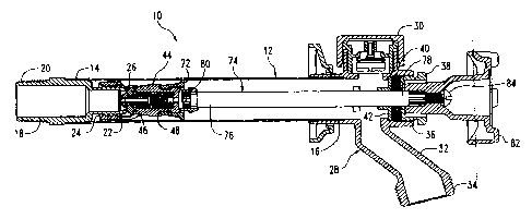
A freezeless wall hydrant has a fluid inlet end connected to a source of pressurized water, and a fluid outlet end. A check valve is placed in the bore of the valve body and is spring loaded to open only when extreme water pressure within the inlet valve lifts a spring loaded piston element to permit the highly pressurized water to move through the bore in the valve body and be relieved as it escapes rearwardly into the original source of pressurized water.


French Abstract

Une prise d'eau murale insensible au gel dispose d'une extrémité d'entrée du liquide reliée à une source d'eau sous pression et d'une extrémité de sortie du liquide. Un clapet anti-retour est placé dans l'alésage du corps de soupape et est actionné par ressort pour ne s'ouvrir que lorsqu'une pression d'eau extrême à l'intérieur de la soupape d'admission soulève un élément du piston actionné par ressort et permet à l'eau soumise à une haute pression de se déplacer dans l'alésage au sein du corps de la soupape et de soulager la prise, car l'eau retourne vers la source originelle de l'eau sous pression.

Claims

Note: Claims are shown in the official language in which they were submitted.


What is claimed is:
1. A freezeless wall hydrant, comprising,
a normally horizontal fluid inlet tube having an interior
end and an exterior end,
a hollow valve fitting rigidly secured to the interior end
of the inlet tube for connection to a source of
pressurized fluid,
a valve seat on an interior end of the valve fitting,
a casting member rigidly secured to the outer end of the
inlet tube and including a drain conduit in
communication with an interior of the inlet tube for
discharging water from the hydrant,
a valve body longitudinally movably mounted in the inlet
tube adjacent the valve fitting,
a valve sealing element on the valve body adapted to engage
and disengage the valve seat to prevent or permit,
respectively, a fluid flow through the valve fitting
into the inlet tube,
an elongated operating rod having a rearward end secured to
the valve body and an outer end protruding from the
casting member for longitudinally moving the valve body
in the inlet tube,
a bore in the valve body connecting the valve fitting and
the inlet tube,
a check valve in the bore of the valve body to normally
prevent fluid flow either into or out of the inlet
tube,
a center bore in the valve body extending between a
forwardly located aperture with a center bore and the
valve sealing element located adjacent the rearward end
of the valve body,
7

a resilient sealing ring adjacent the forwardly located
aperture,
a valve element having an end portion adjacent the resilient
sealing ring and a stem portion of smaller diameter
extending in a rearwardly direction;
a compression spring around the stem portion bearing against
a rearward surface of the end portion of the piston
element and normally urging the piston element to
compress the resilient sealing ring to prevent the flow
of fluid rearwardly through the inlet pipe and through
the center bore of the valve body,
a fluid conduit in the valve body having a rearward end
communicating with the source of pressurized fluid, and
a forward end communicating with the portion of the
bore of the valve body occupied by the compression
spring so that a source of fluid under pressure higher
than a source of pressurized fluid adjacent the hollow
valve fitting will cause the piston element to compress
the compression spring to decompress the resilient
sealing ring so that fluid will flow rearwardly through
the valve body through the forwardly located aperture
therein; thence through the resilient sealing ring,
past the end portion of the piston element, past the
compression spring, and into the fluid conduit of the
valve body to the source of pressurized fluid adjacent
the hollow valve fitting.
2. The hydrant of claim 1 wherein the fluid conduit in the
valve body is a screw having a center bore, and holding the
valve sealing element in place, with the center bore
connecting the source of pressurized fluid to the bore in
the valve body.
8

3. The hydrant of claim 2 wherein the screw is threaded
into a hollow bushing mounted in the bore of the valve body.
4. A freezeless wall hydrant, comprising,
a normally horizontal fluid inlet tube having an interior
end and an exterior end,
a hollow valve fitting rigidly secured to the interior end
of the inlet tube for connection to a source of
pressurized fluid,
a valve seat on an interior end of the valve fitting,
a valve body longitudinally movably mounted in the inlet
tube adjacent the valve fitting,
a valve sealing element on the valve body adapted to engage
and disengage the valve seat to prevent or permit,
respectively, a fluid flow through the valve fitting
into the inlet tube,
a bore in the valve body connecting the valve fitting and
the inlet tube,
a check valve in the bore of the valve body to normally
prevent fluid flow either into or out of the inlet
tube,
a center bore in the valve body extending between a
forwardly located aperture with a center bore and the
valve sealing element located adjacent the rearward end
of the valve body,
a resilient sealing ring adjacent the forwardly located
aperture,
a valve element having an end portion adjacent the resilient
sealing ring extending in a rearwardly direction,
a compression spring bearing against a rearward surface of
the valve element and normally urging the valve element
9

to compress the resilient sealing ring to prevent the
flow of fluid rearwardly through the inlet pipe and
through the center bore of the valve body,
a fluid conduit in the valve body having a rearward end
communicating with the source of pressurized fluid, and
a forward end communicating with the portion of the
bore of the valve body occupied by the compression
spring so that a source of fluid under pressure higher
than a source of pressurized fluid adjacent the hollow
valve fitting will cause the valve element to compress
the compression spring to decompress the resilient
sealing ring so that fluid will flow rearwardly through
the valve body and into the fluid conduit of the valve
body to the source of pressurized fluid adjacent the
hollow valve fitting.
5. The hydrant of claim 4 wherein the fluid conduit in the
valve body is a screw having a center bore, and holding the
valve sealing element in place, with the center bore
connecting the source of pressurized fluid to the bore in
the valve body.
6. The hydrant of claim 5 wherein the screw is threaded
into a hollow bushing mounted in the bore of the valve body.

Description

Note: Descriptions are shown in the official language in which they were submitted.


CA 02488953 2006-12-21
TITLE: FREEZE PROTECTION DEVICE FOR WALL
HYDRANTS/FAUCETS
BACKGROUND OF THE INVENTION
Freezeless wall hydrants and faucets have long been in
existence. They characteristically have a fluid closure
valve located in the end of an inlet pipe located within the
wall or a warmer interior area of the building of which the
wall is a part. This closure valve is operated by an
elongated rod connected to an exterior handle. The
freezeless characteristics of the hydrant are caused by the
closure valve shutting off the flow of water within the wall
or building at a freezing temperature, with the residual
water in the inlet pipe flowing by gravity outwardly through
the conventional outlet drain of the hydrant.
The foregoing structure works very successfully except
in situations where a hose or the like is attached to the
outlet drain of the hydrant, whereupon the residual water is
not able to easily flow by gravity out of the hydrant when
the closure valve connected to the pressurized water is
closed. With a hose attached during freezing weather, the
residual water freezes within the hydrant, and the inlet
pipe or related components thereupon rupture from the
freezing conditions within the hydrant.
It has in recent times been recognized that the rupture
of such a hydrant under freezing weather conditions does not
take place because of the frozen water in the hydrant.
Rather, the rupture results from the ice imposing severe
pressure on the captivated non-frozen fluid in the inlet
pipe. Thus, the increased pressure on this water by the
expanded ice is the principal cause for the rupture of the
hydrant.
1

CA 02488953 2006-12-21
Attempts have been made to permit some backflow to take
place via spring loaded ball bearings (U.S. Pat. No.
6,142,172), but calcium deposits on the ball bearings
sometimes inhibit the process.
Accordingly, it is a principal object of this invention
to provide a freezeless wall hydrant which has the ability
to drain at least some of the residual water in a hydrant
when, under freezing conditions, the residual water towards
the exterior part of the hydrant freezes by reason of a hose
or the like being attached to the discharge nozzle.
It is a further object of this invention to provide a
relief valve for the captured residual water under the
foregoing conditions to escape back towards the supply of
pressurized water when the frozen water in the exterior of
the hydrant creates excessive pressure on the remainder of
the residual water in the hydrant.
These and other objects will be apparent to those
skilled in the art.
BRIEF SUMMARY OF THE INVENTION
A freezeless wall hydrant has an inlet pipe with one
end connected to a source of pressurized water, a water
discharge conduit, and an elongated control rod extending
through the inlet pipe to open and close a fluid valve. A
bore is inserted through the fluid valve with the bore being
in communication with both the source of pressurized water
and the interior portion of the inlet pipe. A check valve
is placed in the bore of the valve body and is spring loaded
to open only when extreme water pressure within the inlet
valve lifts a spring loaded piston element to permit the
highly pressurized water to move through the bore in the
valve body and be relieved as it escapes rearwardly into the
2

CA 02488953 2006-12-21
s
original source of pressurized water. The check valve is
enclosed within a cylindrical housing and is force-fit into
the bore of the valve body. The spring is of sufficient
strength such that it will open the bore to fluid flow in a
rearward direction only when the pressure within the outlet
portion of the inlet conduit is greater than that of the
pressurized source of water normally located upstream from
the valve closure.
BRIEF DESCRIPTION OF THE DRAWINGS
Fig. 1 is a longitudinal sectional view of the hydrant
of this invention;
Fig. 2 is a large scale sectional view of the valve
body in an opened condition which controls flow of
pressurized water through the hydrant; and
Fig. 3 is a sectional view similar to that of Fig. 2
but shows how the valve can allow high pressure backflow
water downstream from the valve body to the supply water
when ice in the hydrant compresses water adjacent the
downstream side of the valve in a backflow direction.
DESCRIPTION OF THE PREFERRED EMBODIMENTS OF THE INVENTION
The hydrant 10 in Fig. 1 has an elongated hollow water
inlet tube 12 which has an interior end 14 and an exterior
end 16. A hollow valve fitting 18 is rearwardly secured to
the interior end 14 of tube 12 and has a threaded end 20
adapted to be secured to a conduit connected to a source of
pressurized fluid (not shown). The fitting 18 has an
interior end 22 with external threads 24 and which terminate
in a valve seat 26.
A casting member 28 has a conventional vacuum breaker
30 secured thereto and is rigidly connected to the exterior
3

CA 02488953 2006-12-21
end 16 of inlet tube 12. A conventional fluid drain conduit
32 is located within casting member 28 and is in
communication with the interior of tube 12. Conventional
threads 34 are located on the discharge end of conduit 32 to
S receive a conventional hose or the like. Casting member 28
also has a threaded aperture 36 which is adapted to receive
a conventional bushing 38 which in turn receives packing 40
which is held in tight engagement with bushing 38 by packing
washer 42 (Fig. l) .
Adjacent the interior end of valve fitting 18 is a
valve body 44 adapted for longitudinal movement in the
interior end of 14 of tube 12. Valve body 44 has an
interior end 46, an exterior end 48 and an elongated center
bore 50 extending therethrough (Figs. 2 and 3). A shoulder
52 with center bore 54 is located in bore 50. A
compressible sealing ring 56 is located in bore 50 adjacent
shoulder 52. A T-shaped piston element or valve 58 having a
circular top 58A and a rearwardly extending stem 58B of
narrower diameter, creating a void 58C therearound. An
internally threaded bushing 59 is fractionally mounted
within the rearward end of bore 50. A bore 59A is located
in bushing 59 adjacent the rearward end of stem 58B of
piston element 58. Coil spring 61 is normally compressed
between bushing 59 and piston top 58A to compress sealing
ring 56. A space 60 is provided around the top 58A of
pliston element 58 to allow the passage of fluid from center
bore 54, thence through space 60 when compression of ring 56
is relieved, as will be discussed hereafter.
A valve seat member 62 is mounted on screw 64 and has a
center bore 66 and is received by the internal threads of
bushing 59. The screw 64 binds the sealing member 62 to
bushing 59 and valve body 44.
4

CA 02488953 2006-12-21
Threaded arms 67 extend rearwardly from body 44 and
threadably engage the threads 24 on the interior end 22 of
valve fitting 18.
A plurality of spherical spline teeth 70 extend
outwardly from space 68. A conventional check valve member
72 extends around the spline teeth 70 and is adapted to
engage the interior surface of the inlet tube 12. The check
valve member 72 conventionally permits fluid flow only in a
direction towards the drain conduit 32, but prevents fluid
flow in the inlet pipe in opposite direction.'
A conventional elongated rod control 74 is located
within the inlet pipe 12 and has a rearward end 76 and a
forward end 78. Spline grooves 80 are formed in the
'rearward end 76 of the rod control and are adapted to engage
the spline teeth 70 located at the forward end of the body
44. A conventional handle wheel 82 is spline-mounted on the
forward end 78 of rod control 74 and is held in place by
conventional screw 84.
In the event that a hose is attached to the fluid drain
conduit 32 in freezing temperatures, the residual water
which ordinarily would flow out of the conduit 32 if the
hose were not attached when the valve member 42 is in a
closed condition will be captured within the conduit 32 and
the interior of tube 12. This residual captured water will
first begin to freeze in the discharge conduit 32 and
adjacent the exterior end 16 of tube 12. The presence of
ice in that portion of the hydrant will cause excessive
pressure possibly as high as 4,000 PSI in unfrozen residual
water in the end 14 of tube 12. This is because water
volume expands by about 8% as it turns to ice. Ordinarily,
water under that much pressure would rupture at least the
inlet pipe 12. However, with the present invention, this
5

CA 02488953 2006-12-21
increased pressure exerted on the residual water in the
inlet pipe 12 occasioned by the formation of ice in the
exterior end thereof will exert pressure on piston top 58A
which will compress spring 61 against bushing 59 and thus
releases the compression of ring 56. This will permit the
highly compressed fluid in the rearward end of tube 12 to
flow around the ring 56, thence around the top 58A through
space 60, thence around spring 61, thence through bore 59A,
thence the center bore 66 of screw 64, and thence into the
interior of the water supply in valve fitting 18. The water
pressure in valve fitting 18 is normally in the range of 55
PSI, so the above process will continue to balance the water
pressure on both ends of the valve body 44, thus eliminating
any rupture of the tube 12 caused by the freezing
phenomenon.
Thus, from the foregoing, it is seen that this
invention will keep the ordinary freezeless hydrant from
becoming ruptured whenever a hose or the like is
inadvertently left on the discharge conduit thereof. This
successful result takes place because the formation of ice
in such a hydrant under those conditions will permit the
back flow of residual water in the hydrant to move through
the otherwise closed hydrant valve into the original source
of pressurized water. This relief of pressure will prevent
the hydrant from rupturing under the freezing conditions.
It is therefore seen that this invention will achieve all of
its stated objectives.
6

Representative Drawing
A single figure which represents the drawing illustrating the invention.
Administrative Status

2024-08-01:As part of the Next Generation Patents (NGP) transition, the Canadian Patents Database (CPD) now contains a more detailed Event History, which replicates the Event Log of our new back-office solution.

Please note that "Inactive:" events refers to events no longer in use in our new back-office solution.

For a clearer understanding of the status of the application/patent presented on this page, the site Disclaimer , as well as the definitions for Patent , Event History , Maintenance Fee  and Payment History  should be consulted.

Event History

Description Date
Common Representative Appointed 2019-10-30
Change of Address or Method of Correspondence Request Received 2018-01-12
Maintenance Request Received 2016-11-30
Maintenance Request Received 2014-12-01
Maintenance Request Received 2012-11-30
Inactive: Late MF processed 2011-12-19
Letter Sent 2011-12-05
Grant by Issuance 2007-04-24
Inactive: Cover page published 2007-04-23
Pre-grant 2007-02-08
Inactive: Final fee received 2007-02-08
Notice of Allowance is Issued 2007-01-10
Letter Sent 2007-01-10
Notice of Allowance is Issued 2007-01-10
Inactive: Received pages at allowance 2006-12-21
Inactive: Office letter 2006-09-27
Inactive: Approved for allowance (AFA) 2006-09-11
Inactive: IPC from MCD 2006-03-12
Inactive: Cover page published 2005-06-05
Application Published (Open to Public Inspection) 2005-06-05
Letter Sent 2005-03-15
Inactive: IPC assigned 2005-03-11
Inactive: First IPC assigned 2005-03-11
Inactive: Single transfer 2005-02-24
Inactive: Courtesy letter - Evidence 2005-01-19
Filing Requirements Determined Compliant 2005-01-19
Inactive: Filing certificate - RFE (English) 2005-01-19
Letter Sent 2005-01-18
Application Received - Regular National 2005-01-18
Request for Examination Requirements Determined Compliant 2004-12-03
All Requirements for Examination Determined Compliant 2004-12-03

Abandonment History

There is no abandonment history.

Maintenance Fee

The last payment was received on 2006-11-10

Note : If the full payment has not been received on or before the date indicated, a further fee may be required which may be one of the following

  • the reinstatement fee;
  • the late payment fee; or
  • additional fee to reverse deemed expiry.

Patent fees are adjusted on the 1st of January every year. The amounts above are the current amounts if received by December 31 of the current year.
Please refer to the CIPO Patent Fees web page to see all current fee amounts.

Owners on Record

Note: Records showing the ownership history in alphabetical order.

Current Owners on Record
WCM INDUSTRIES, INC.
Past Owners on Record
ALFRED F. DICKEY
CODY W. JACKSON
WILLIAM T. BALL
Past Owners that do not appear in the "Owners on Record" listing will appear in other documentation within the application.
Documents

To view selected files, please enter reCAPTCHA code :


To view images, click a link in the Document Description column. To download the documents, select one or more checkboxes in the first column and then click the "Download Selected in PDF format (Zip Archive)" or the "Download Selected as Single PDF" button.

List of published and non-published patent-specific documents on the CPD .

If you have any difficulty accessing content, you can call the Client Service Centre at 1-866-997-1936 or send them an e-mail at CIPO Client Service Centre.


Document
Description 
Date
(yyyy-mm-dd) 
Number of pages   Size of Image (KB) 
Abstract 2004-12-02 1 17
Description 2004-12-02 6 271
Claims 2004-12-02 4 157
Drawings 2004-12-02 3 66
Representative drawing 2005-05-11 1 15
Abstract 2006-12-20 1 14
Description 2006-12-20 6 251
Claims 2006-12-20 4 137
Acknowledgement of Request for Examination 2005-01-17 1 176
Filing Certificate (English) 2005-01-18 1 158
Courtesy - Certificate of registration (related document(s)) 2005-03-14 1 105
Reminder of maintenance fee due 2006-08-06 1 110
Commissioner's Notice - Application Found Allowable 2007-01-09 1 161
Maintenance Fee Notice 2011-12-18 1 171
Late Payment Acknowledgement 2011-12-18 1 164
Correspondence 2005-01-18 1 26
Correspondence 2006-09-26 1 22
Fees 2006-11-09 1 28
Correspondence 2006-12-20 12 428
Correspondence 2007-02-07 1 26
Fees 2012-11-29 1 25
Fees 2014-11-30 2 55
Maintenance fee payment 2016-11-29 2 51