Sélection de la langue

Search

Sommaire du brevet 2488953 

Énoncé de désistement de responsabilité concernant l'information provenant de tiers

Une partie des informations de ce site Web a été fournie par des sources externes. Le gouvernement du Canada n'assume aucune responsabilité concernant la précision, l'actualité ou la fiabilité des informations fournies par les sources externes. Les utilisateurs qui désirent employer cette information devraient consulter directement la source des informations. Le contenu fourni par les sources externes n'est pas assujetti aux exigences sur les langues officielles, la protection des renseignements personnels et l'accessibilité.

Disponibilité de l'Abrégé et des Revendications

L'apparition de différences dans le texte et l'image des Revendications et de l'Abrégé dépend du moment auquel le document est publié. Les textes des Revendications et de l'Abrégé sont affichés :

  • lorsque la demande peut être examinée par le public;
  • lorsque le brevet est émis (délivrance).
(12) Brevet: (11) CA 2488953
(54) Titre français: DISPOSITIF DE PROTECTION CONTRE LE GEL POUR PRISES D'EAU/ROBINETS EXTERIEURS
(54) Titre anglais: FREEZE PROTECTION DEVICE FOR WALL HYDRANTS/FAUCETS
Statut: Accordé et délivré
Données bibliographiques
(51) Classification internationale des brevets (CIB):
  • E03B 7/10 (2006.01)
  • E03B 9/14 (2006.01)
  • F16K 31/46 (2006.01)
  • F16K 39/02 (2006.01)
(72) Inventeurs :
  • DICKEY, ALFRED F. (Etats-Unis d'Amérique)
  • JACKSON, CODY W. (Etats-Unis d'Amérique)
  • BALL, WILLIAM T. (Etats-Unis d'Amérique)
(73) Titulaires :
  • WCM INDUSTRIES, INC.
(71) Demandeurs :
  • WCM INDUSTRIES, INC. (Etats-Unis d'Amérique)
(74) Agent: SMART & BIGGAR LP
(74) Co-agent:
(45) Délivré: 2007-04-24
(22) Date de dépôt: 2004-12-03
(41) Mise à la disponibilité du public: 2005-06-05
Requête d'examen: 2004-12-03
Licence disponible: S.O.
Cédé au domaine public: S.O.
(25) Langue des documents déposés: Anglais

Traité de coopération en matière de brevets (PCT): Non

(30) Données de priorité de la demande:
Numéro de la demande Pays / territoire Date
10/729,778 (Etats-Unis d'Amérique) 2003-12-05

Abrégés

Abrégé français

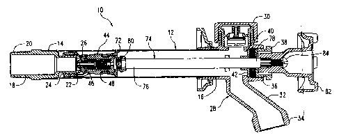
Une prise d'eau murale insensible au gel dispose d'une extrémité d'entrée du liquide reliée à une source d'eau sous pression et d'une extrémité de sortie du liquide. Un clapet anti-retour est placé dans l'alésage du corps de soupape et est actionné par ressort pour ne s'ouvrir que lorsqu'une pression d'eau extrême à l'intérieur de la soupape d'admission soulève un élément du piston actionné par ressort et permet à l'eau soumise à une haute pression de se déplacer dans l'alésage au sein du corps de la soupape et de soulager la prise, car l'eau retourne vers la source originelle de l'eau sous pression.


Abrégé anglais

A freezeless wall hydrant has a fluid inlet end connected to a source of pressurized water, and a fluid outlet end. A check valve is placed in the bore of the valve body and is spring loaded to open only when extreme water pressure within the inlet valve lifts a spring loaded piston element to permit the highly pressurized water to move through the bore in the valve body and be relieved as it escapes rearwardly into the original source of pressurized water.

Revendications

Note : Les revendications sont présentées dans la langue officielle dans laquelle elles ont été soumises.


What is claimed is:
1. A freezeless wall hydrant, comprising,
a normally horizontal fluid inlet tube having an interior
end and an exterior end,
a hollow valve fitting rigidly secured to the interior end
of the inlet tube for connection to a source of
pressurized fluid,
a valve seat on an interior end of the valve fitting,
a casting member rigidly secured to the outer end of the
inlet tube and including a drain conduit in
communication with an interior of the inlet tube for
discharging water from the hydrant,
a valve body longitudinally movably mounted in the inlet
tube adjacent the valve fitting,
a valve sealing element on the valve body adapted to engage
and disengage the valve seat to prevent or permit,
respectively, a fluid flow through the valve fitting
into the inlet tube,
an elongated operating rod having a rearward end secured to
the valve body and an outer end protruding from the
casting member for longitudinally moving the valve body
in the inlet tube,
a bore in the valve body connecting the valve fitting and
the inlet tube,
a check valve in the bore of the valve body to normally
prevent fluid flow either into or out of the inlet
tube,
a center bore in the valve body extending between a
forwardly located aperture with a center bore and the
valve sealing element located adjacent the rearward end
of the valve body,
7

a resilient sealing ring adjacent the forwardly located
aperture,
a valve element having an end portion adjacent the resilient
sealing ring and a stem portion of smaller diameter
extending in a rearwardly direction;
a compression spring around the stem portion bearing against
a rearward surface of the end portion of the piston
element and normally urging the piston element to
compress the resilient sealing ring to prevent the flow
of fluid rearwardly through the inlet pipe and through
the center bore of the valve body,
a fluid conduit in the valve body having a rearward end
communicating with the source of pressurized fluid, and
a forward end communicating with the portion of the
bore of the valve body occupied by the compression
spring so that a source of fluid under pressure higher
than a source of pressurized fluid adjacent the hollow
valve fitting will cause the piston element to compress
the compression spring to decompress the resilient
sealing ring so that fluid will flow rearwardly through
the valve body through the forwardly located aperture
therein; thence through the resilient sealing ring,
past the end portion of the piston element, past the
compression spring, and into the fluid conduit of the
valve body to the source of pressurized fluid adjacent
the hollow valve fitting.
2. The hydrant of claim 1 wherein the fluid conduit in the
valve body is a screw having a center bore, and holding the
valve sealing element in place, with the center bore
connecting the source of pressurized fluid to the bore in
the valve body.
8

3. The hydrant of claim 2 wherein the screw is threaded
into a hollow bushing mounted in the bore of the valve body.
4. A freezeless wall hydrant, comprising,
a normally horizontal fluid inlet tube having an interior
end and an exterior end,
a hollow valve fitting rigidly secured to the interior end
of the inlet tube for connection to a source of
pressurized fluid,
a valve seat on an interior end of the valve fitting,
a valve body longitudinally movably mounted in the inlet
tube adjacent the valve fitting,
a valve sealing element on the valve body adapted to engage
and disengage the valve seat to prevent or permit,
respectively, a fluid flow through the valve fitting
into the inlet tube,
a bore in the valve body connecting the valve fitting and
the inlet tube,
a check valve in the bore of the valve body to normally
prevent fluid flow either into or out of the inlet
tube,
a center bore in the valve body extending between a
forwardly located aperture with a center bore and the
valve sealing element located adjacent the rearward end
of the valve body,
a resilient sealing ring adjacent the forwardly located
aperture,
a valve element having an end portion adjacent the resilient
sealing ring extending in a rearwardly direction,
a compression spring bearing against a rearward surface of
the valve element and normally urging the valve element
9

to compress the resilient sealing ring to prevent the
flow of fluid rearwardly through the inlet pipe and
through the center bore of the valve body,
a fluid conduit in the valve body having a rearward end
communicating with the source of pressurized fluid, and
a forward end communicating with the portion of the
bore of the valve body occupied by the compression
spring so that a source of fluid under pressure higher
than a source of pressurized fluid adjacent the hollow
valve fitting will cause the valve element to compress
the compression spring to decompress the resilient
sealing ring so that fluid will flow rearwardly through
the valve body and into the fluid conduit of the valve
body to the source of pressurized fluid adjacent the
hollow valve fitting.
5. The hydrant of claim 4 wherein the fluid conduit in the
valve body is a screw having a center bore, and holding the
valve sealing element in place, with the center bore
connecting the source of pressurized fluid to the bore in
the valve body.
6. The hydrant of claim 5 wherein the screw is threaded
into a hollow bushing mounted in the bore of the valve body.

Description

Note : Les descriptions sont présentées dans la langue officielle dans laquelle elles ont été soumises.


CA 02488953 2006-12-21
TITLE: FREEZE PROTECTION DEVICE FOR WALL
HYDRANTS/FAUCETS
BACKGROUND OF THE INVENTION
Freezeless wall hydrants and faucets have long been in
existence. They characteristically have a fluid closure
valve located in the end of an inlet pipe located within the
wall or a warmer interior area of the building of which the
wall is a part. This closure valve is operated by an
elongated rod connected to an exterior handle. The
freezeless characteristics of the hydrant are caused by the
closure valve shutting off the flow of water within the wall
or building at a freezing temperature, with the residual
water in the inlet pipe flowing by gravity outwardly through
the conventional outlet drain of the hydrant.
The foregoing structure works very successfully except
in situations where a hose or the like is attached to the
outlet drain of the hydrant, whereupon the residual water is
not able to easily flow by gravity out of the hydrant when
the closure valve connected to the pressurized water is
closed. With a hose attached during freezing weather, the
residual water freezes within the hydrant, and the inlet
pipe or related components thereupon rupture from the
freezing conditions within the hydrant.
It has in recent times been recognized that the rupture
of such a hydrant under freezing weather conditions does not
take place because of the frozen water in the hydrant.
Rather, the rupture results from the ice imposing severe
pressure on the captivated non-frozen fluid in the inlet
pipe. Thus, the increased pressure on this water by the
expanded ice is the principal cause for the rupture of the
hydrant.
1

CA 02488953 2006-12-21
Attempts have been made to permit some backflow to take
place via spring loaded ball bearings (U.S. Pat. No.
6,142,172), but calcium deposits on the ball bearings
sometimes inhibit the process.
Accordingly, it is a principal object of this invention
to provide a freezeless wall hydrant which has the ability
to drain at least some of the residual water in a hydrant
when, under freezing conditions, the residual water towards
the exterior part of the hydrant freezes by reason of a hose
or the like being attached to the discharge nozzle.
It is a further object of this invention to provide a
relief valve for the captured residual water under the
foregoing conditions to escape back towards the supply of
pressurized water when the frozen water in the exterior of
the hydrant creates excessive pressure on the remainder of
the residual water in the hydrant.
These and other objects will be apparent to those
skilled in the art.
BRIEF SUMMARY OF THE INVENTION
A freezeless wall hydrant has an inlet pipe with one
end connected to a source of pressurized water, a water
discharge conduit, and an elongated control rod extending
through the inlet pipe to open and close a fluid valve. A
bore is inserted through the fluid valve with the bore being
in communication with both the source of pressurized water
and the interior portion of the inlet pipe. A check valve
is placed in the bore of the valve body and is spring loaded
to open only when extreme water pressure within the inlet
valve lifts a spring loaded piston element to permit the
highly pressurized water to move through the bore in the
valve body and be relieved as it escapes rearwardly into the
2

CA 02488953 2006-12-21
s
original source of pressurized water. The check valve is
enclosed within a cylindrical housing and is force-fit into
the bore of the valve body. The spring is of sufficient
strength such that it will open the bore to fluid flow in a
rearward direction only when the pressure within the outlet
portion of the inlet conduit is greater than that of the
pressurized source of water normally located upstream from
the valve closure.
BRIEF DESCRIPTION OF THE DRAWINGS
Fig. 1 is a longitudinal sectional view of the hydrant
of this invention;
Fig. 2 is a large scale sectional view of the valve
body in an opened condition which controls flow of
pressurized water through the hydrant; and
Fig. 3 is a sectional view similar to that of Fig. 2
but shows how the valve can allow high pressure backflow
water downstream from the valve body to the supply water
when ice in the hydrant compresses water adjacent the
downstream side of the valve in a backflow direction.
DESCRIPTION OF THE PREFERRED EMBODIMENTS OF THE INVENTION
The hydrant 10 in Fig. 1 has an elongated hollow water
inlet tube 12 which has an interior end 14 and an exterior
end 16. A hollow valve fitting 18 is rearwardly secured to
the interior end 14 of tube 12 and has a threaded end 20
adapted to be secured to a conduit connected to a source of
pressurized fluid (not shown). The fitting 18 has an
interior end 22 with external threads 24 and which terminate
in a valve seat 26.
A casting member 28 has a conventional vacuum breaker
30 secured thereto and is rigidly connected to the exterior
3

CA 02488953 2006-12-21
end 16 of inlet tube 12. A conventional fluid drain conduit
32 is located within casting member 28 and is in
communication with the interior of tube 12. Conventional
threads 34 are located on the discharge end of conduit 32 to
S receive a conventional hose or the like. Casting member 28
also has a threaded aperture 36 which is adapted to receive
a conventional bushing 38 which in turn receives packing 40
which is held in tight engagement with bushing 38 by packing
washer 42 (Fig. l) .
Adjacent the interior end of valve fitting 18 is a
valve body 44 adapted for longitudinal movement in the
interior end of 14 of tube 12. Valve body 44 has an
interior end 46, an exterior end 48 and an elongated center
bore 50 extending therethrough (Figs. 2 and 3). A shoulder
52 with center bore 54 is located in bore 50. A
compressible sealing ring 56 is located in bore 50 adjacent
shoulder 52. A T-shaped piston element or valve 58 having a
circular top 58A and a rearwardly extending stem 58B of
narrower diameter, creating a void 58C therearound. An
internally threaded bushing 59 is fractionally mounted
within the rearward end of bore 50. A bore 59A is located
in bushing 59 adjacent the rearward end of stem 58B of
piston element 58. Coil spring 61 is normally compressed
between bushing 59 and piston top 58A to compress sealing
ring 56. A space 60 is provided around the top 58A of
pliston element 58 to allow the passage of fluid from center
bore 54, thence through space 60 when compression of ring 56
is relieved, as will be discussed hereafter.
A valve seat member 62 is mounted on screw 64 and has a
center bore 66 and is received by the internal threads of
bushing 59. The screw 64 binds the sealing member 62 to
bushing 59 and valve body 44.
4

CA 02488953 2006-12-21
Threaded arms 67 extend rearwardly from body 44 and
threadably engage the threads 24 on the interior end 22 of
valve fitting 18.
A plurality of spherical spline teeth 70 extend
outwardly from space 68. A conventional check valve member
72 extends around the spline teeth 70 and is adapted to
engage the interior surface of the inlet tube 12. The check
valve member 72 conventionally permits fluid flow only in a
direction towards the drain conduit 32, but prevents fluid
flow in the inlet pipe in opposite direction.'
A conventional elongated rod control 74 is located
within the inlet pipe 12 and has a rearward end 76 and a
forward end 78. Spline grooves 80 are formed in the
'rearward end 76 of the rod control and are adapted to engage
the spline teeth 70 located at the forward end of the body
44. A conventional handle wheel 82 is spline-mounted on the
forward end 78 of rod control 74 and is held in place by
conventional screw 84.
In the event that a hose is attached to the fluid drain
conduit 32 in freezing temperatures, the residual water
which ordinarily would flow out of the conduit 32 if the
hose were not attached when the valve member 42 is in a
closed condition will be captured within the conduit 32 and
the interior of tube 12. This residual captured water will
first begin to freeze in the discharge conduit 32 and
adjacent the exterior end 16 of tube 12. The presence of
ice in that portion of the hydrant will cause excessive
pressure possibly as high as 4,000 PSI in unfrozen residual
water in the end 14 of tube 12. This is because water
volume expands by about 8% as it turns to ice. Ordinarily,
water under that much pressure would rupture at least the
inlet pipe 12. However, with the present invention, this
5

CA 02488953 2006-12-21
increased pressure exerted on the residual water in the
inlet pipe 12 occasioned by the formation of ice in the
exterior end thereof will exert pressure on piston top 58A
which will compress spring 61 against bushing 59 and thus
releases the compression of ring 56. This will permit the
highly compressed fluid in the rearward end of tube 12 to
flow around the ring 56, thence around the top 58A through
space 60, thence around spring 61, thence through bore 59A,
thence the center bore 66 of screw 64, and thence into the
interior of the water supply in valve fitting 18. The water
pressure in valve fitting 18 is normally in the range of 55
PSI, so the above process will continue to balance the water
pressure on both ends of the valve body 44, thus eliminating
any rupture of the tube 12 caused by the freezing
phenomenon.
Thus, from the foregoing, it is seen that this
invention will keep the ordinary freezeless hydrant from
becoming ruptured whenever a hose or the like is
inadvertently left on the discharge conduit thereof. This
successful result takes place because the formation of ice
in such a hydrant under those conditions will permit the
back flow of residual water in the hydrant to move through
the otherwise closed hydrant valve into the original source
of pressurized water. This relief of pressure will prevent
the hydrant from rupturing under the freezing conditions.
It is therefore seen that this invention will achieve all of
its stated objectives.
6

Dessin représentatif
Une figure unique qui représente un dessin illustrant l'invention.
États administratifs

2024-08-01 : Dans le cadre de la transition vers les Brevets de nouvelle génération (BNG), la base de données sur les brevets canadiens (BDBC) contient désormais un Historique d'événement plus détaillé, qui reproduit le Journal des événements de notre nouvelle solution interne.

Veuillez noter que les événements débutant par « Inactive : » se réfèrent à des événements qui ne sont plus utilisés dans notre nouvelle solution interne.

Pour une meilleure compréhension de l'état de la demande ou brevet qui figure sur cette page, la rubrique Mise en garde , et les descriptions de Brevet , Historique d'événement , Taxes périodiques et Historique des paiements devraient être consultées.

Historique d'événement

Description Date
Représentant commun nommé 2019-10-30
Requête pour le changement d'adresse ou de mode de correspondance reçue 2018-01-12
Requête visant le maintien en état reçue 2016-11-30
Requête visant le maintien en état reçue 2014-12-01
Requête visant le maintien en état reçue 2012-11-30
Inactive : TME en retard traitée 2011-12-19
Lettre envoyée 2011-12-05
Accordé par délivrance 2007-04-24
Inactive : Page couverture publiée 2007-04-23
Préoctroi 2007-02-08
Inactive : Taxe finale reçue 2007-02-08
Un avis d'acceptation est envoyé 2007-01-10
Lettre envoyée 2007-01-10
Un avis d'acceptation est envoyé 2007-01-10
Inactive : Pages reçues à l'acceptation 2006-12-21
Inactive : Lettre officielle 2006-09-27
Inactive : Approuvée aux fins d'acceptation (AFA) 2006-09-11
Inactive : CIB de MCD 2006-03-12
Inactive : Page couverture publiée 2005-06-05
Demande publiée (accessible au public) 2005-06-05
Lettre envoyée 2005-03-15
Inactive : CIB attribuée 2005-03-11
Inactive : CIB en 1re position 2005-03-11
Inactive : Transfert individuel 2005-02-24
Inactive : Lettre de courtoisie - Preuve 2005-01-19
Exigences de dépôt - jugé conforme 2005-01-19
Inactive : Certificat de dépôt - RE (Anglais) 2005-01-19
Lettre envoyée 2005-01-18
Demande reçue - nationale ordinaire 2005-01-18
Exigences pour une requête d'examen - jugée conforme 2004-12-03
Toutes les exigences pour l'examen - jugée conforme 2004-12-03

Historique d'abandonnement

Il n'y a pas d'historique d'abandonnement

Taxes périodiques

Le dernier paiement a été reçu le 2006-11-10

Avis : Si le paiement en totalité n'a pas été reçu au plus tard à la date indiquée, une taxe supplémentaire peut être imposée, soit une des taxes suivantes :

  • taxe de rétablissement ;
  • taxe pour paiement en souffrance ; ou
  • taxe additionnelle pour le renversement d'une péremption réputée.

Les taxes sur les brevets sont ajustées au 1er janvier de chaque année. Les montants ci-dessus sont les montants actuels s'ils sont reçus au plus tard le 31 décembre de l'année en cours.
Veuillez vous référer à la page web des taxes sur les brevets de l'OPIC pour voir tous les montants actuels des taxes.

Titulaires au dossier

Les titulaires actuels et antérieures au dossier sont affichés en ordre alphabétique.

Titulaires actuels au dossier
WCM INDUSTRIES, INC.
Titulaires antérieures au dossier
ALFRED F. DICKEY
CODY W. JACKSON
WILLIAM T. BALL
Les propriétaires antérieurs qui ne figurent pas dans la liste des « Propriétaires au dossier » apparaîtront dans d'autres documents au dossier.
Documents

Pour visionner les fichiers sélectionnés, entrer le code reCAPTCHA :


Pour visualiser une image, cliquer sur un lien dans la colonne description du document. Pour télécharger l'image (les images), cliquer l'une ou plusieurs cases à cocher dans la première colonne et ensuite cliquer sur le bouton "Télécharger sélection en format PDF (archive Zip)" ou le bouton "Télécharger sélection (en un fichier PDF fusionné)".

Liste des documents de brevet publiés et non publiés sur la BDBC .

Si vous avez des difficultés à accéder au contenu, veuillez communiquer avec le Centre de services à la clientèle au 1-866-997-1936, ou envoyer un courriel au Centre de service à la clientèle de l'OPIC.


Description du
Document 
Date
(aaaa-mm-jj) 
Nombre de pages   Taille de l'image (Ko) 
Abrégé 2004-12-02 1 17
Description 2004-12-02 6 271
Revendications 2004-12-02 4 157
Dessins 2004-12-02 3 66
Dessin représentatif 2005-05-11 1 15
Abrégé 2006-12-20 1 14
Description 2006-12-20 6 251
Revendications 2006-12-20 4 137
Accusé de réception de la requête d'examen 2005-01-17 1 176
Certificat de dépôt (anglais) 2005-01-18 1 158
Courtoisie - Certificat d'enregistrement (document(s) connexe(s)) 2005-03-14 1 105
Rappel de taxe de maintien due 2006-08-06 1 110
Avis du commissaire - Demande jugée acceptable 2007-01-09 1 161
Avis concernant la taxe de maintien 2011-12-18 1 171
Quittance d'un paiement en retard 2011-12-18 1 164
Correspondance 2005-01-18 1 26
Correspondance 2006-09-26 1 22
Taxes 2006-11-09 1 28
Correspondance 2006-12-20 12 428
Correspondance 2007-02-07 1 26
Taxes 2012-11-29 1 25
Taxes 2014-11-30 2 55
Paiement de taxe périodique 2016-11-29 2 51