Note: Descriptions are shown in the official language in which they were submitted.
CA 02489162 2009-08-06
WO 2004/087478 PCT/US2004/00902-5
RIDE CONTROL CONSTANT CONTACT SIDE BEARING ARRANGEMENT
BACKGROUND OF THE INVENTION
1. Field of Invention
[0001] The present invention relates to an improved side bearing design for
mounting on a railroad car truck bolster that allows long travel, substantial
weight reduction,
improved hunting and curving characteristics, and various safety features.
2. Description of Related Art
[0002] In a typical railway freight train, such as that shown in Fig. 1,
railway cars
12, 14 are connected end to end by couplers 16, 18. Couplers 16, 18 are each
received in
draft sills 20, 22 of each respective car along with hydraulic cushioning or
other shock-
absorbing assemblies (unshown). Draft sills 20, 22 are provided at the ends of
the railway
car's center sill, and include center plates that rest in center plate bowls
of railway car trucks
26,?8.
[0003] As better sho,,;m in Figure 2, each typical car truck 26 includes a
pair of side
frames 30, 32 supported on wheel sets 34, 36. A hollow bolster 38 extends
between and is
supported on springs 40 mounted on the side frames. A bolster center plate 24
is provided
having a central opening 42. The bolster center plate bowl 24 receives and
supports a
circular center plate of the draft sill 20. Side bearing pads 60 are provided
laterally to each
side of center plate 24 on bolster 33. Side frames 30, 32 comprise a top
member 44,
compression member 46, tension member 48, column 50, gib 52, pedestal 54,
pedestal roof
56, bearing 58 and bearing adapter 62.
[0004] Constant contact side bearings are commonly used on railroad car
trucks.
They are typically located on the truck bolster, such as on side bearing pads
60, but may be
located elsewhere. Some prior designs have used a single helical spring
mounted between a
base and a cap. Others use multiple helical springs or elastomer elements.
Exemplary known
side bearing arrangements include U.S. Patent No. 3,748,001 to Neumann et al.
and U.S.
Patent No. 4,130,066 to Mulcahy.
[0005] Typical side bearing arrangements are designed to control hunting of
the
railroad car. That is, as the semi-conical wheels of the railcar truck ride
along a railroad
track, a yaw axis motion is induced in the railroad car truck. As the truck
yaws, part of the
side bearing is made to slide across the underside the wear plate bolted to
the railroad car
body bolster. The resulting friction prodiuces an opposing torque that acts to
prevent this yaw
CA 02489162 2004-12-07
WO 2004/087478 PCT/US2004/009025
2
motion. Another purpose of railroad car truck side bearings is to control or
limit the roll
motion of the car body. Most prior side bearing designs limited travel of the
bearings to
about 5/16". The maximum travel of such side bearings is specified by the
Association of
American Railroads (AAR) standards. Previous standards, such as M-948-77,
limited travel
to 5/16" for many applications.
[0006] New standards have evolved requiring side bearings that have improved
hunting, curving and other properties to further increase the safety and
design of railcars.
The most recent AAR standard is M-976 that now allows for long travel side
bearings and
has several new requirements, such as new specifications for bearing preloads.
Preload is
defined as the force applied by the spring element when the Constant Contact
Side Bearing is
set at the prescribed height.
SUMMARY OF THE INVENTION
[0007] There is a need for improved side bearings for railroad cars that can
me-et or
exceed these new AAR standards, such as M-976 or Rule 88 of the AAR Office
Manual.
[0008] There also is a need for side bearings with better wear characteristics
to
increase service life.
[0009] There further is a need for side bearings that can be designed for a
particular
application by incorporating design features that prevent interchangeability
of incorrect
components for that application.
[0010] There also is a need for a side bearing which maintains the preload
force
within 10% of the new condition for a long time. Preferably, this condition
should be a
minimum of 10 years or one million miles.
[0011] There also is a need for redesigned spring rates to improve handling
characteristics of the truck and railway car.
[0012] There also is a need for a standardized set of springs that can reduce
parts
inventories of various custom spring sizes.
[0013] The above and other advantages are achieved by various embodiments of
the
invention.
[0014] In exemplary embodiments, long travel can be achieved in a side bearing
arrangement for railroad car trucks by a combination of features, including
reduction of base
and/or cap heights and/or reduction of the spring solid height to accommodate
5/8"
travel or more before the spring is fully compressed (solid) and before the
base and cap
bottom out.
CA 02489162 2004-12-07
WO 2004/087478 PCT/US2004/009025
3
[0015] In exemplary embodiments, substantial weight reduction is achieved by
reducing sides and thicknesses of the base and cap in areas not needed for
structural rigidity.
[0016] In exemplary embodiments, improved inspection capabilities are achieved
by addition of an inspection slot to the base and increasing a corresponding
side cutout in the
cap to provide a viewing window of considerable size that allows inspection of
the spring and
other internal components of the side bearing during use. This feature also is
able to achieve
weight saving advantages over prior designs.
[0017] In exemplary embodiments, various design features are incorporated to
the
base and/or cap to prevent interchangeability with improper components. This
may include
features that allow mating of only matching base and cap components. Such
mating may
further include features that prevent improper orientation of the base
relative to the cap. Such
interchangeability prevention features may further include features that
prevent use of
improper spring(s) with the matching base and cap. Also, the springs can be
wound in the
opposite direction of the adjacent spring to preclude one spring interfering
with the travel of
this adjacent spring.
[0013] In exemplary embodiments, improved, longer fatigue life is achieved by
increasing the hardness of the components from Grade C to Grade E.
[0019] In exemplary embodiments, improved operation of the side bearing,
including improved control and hunting characteristics, is achieved by careful
control of
longitudinal clearances between the cap and base. This has been found to be
important to
prevent excessive movement between the cap and base, as well as reduce
associated impact
forces, stresses and wear.
[0020] In exemplary embodiments, improved characteristics of the side bearing
and
service life are achieved by strategic placement of hardened wear surfaces.
[0021] In exemplary embodiments, improved tracking, curving and load leveling
characteristics are achieved without adversely affecting hunting
characteristics by changing
the spring constant to be within a predetermined range, preferably between
4000-6000 lb/in.
[0022] In exemplary embodiments, a standardized set of three different springs
are
provided that can be mixed and matched in various combinations to achieve
different preload
values for use in a multitude of applications, while reducing the need
forspecial, custom-
designed springs for each application.
[0023] In exemplary embodiments, a better contact surface arrangement with a
car
body wear plate is achieved by coping the cap corners and increasing the
flatness of the cap
top contact surface to improve wear characteristics, =such as reduced gouging.
CA 02489162 2004-12-07
WO 2004/087478 PCT/US2004/009025
4
BRIEF DESCRIPTION OF THE DRAWINGS
[0024] The invention will be described with reference to the following
drawings,
wherein:
[0025] Figure 1 is a schematic elevation of the coupled ends of two typical
railroad
cars;
[0026] Figure 2 is a perspective view of a typical railway car truck for use
with the
present invention;
[0027] Figure 3 is an exploded perspective view of an exemplary constaint
contact
side bearing according to the invention;
[0028] Figure 4 is a top view of an exemplary base according to the invention;
[0029] Figure 5 is a cross-sectional view of the base of Figure 4 taken along
lines 5-
5;
[0030] Figure 6 is a top view of an exemplary cap according to the invention;
[0031] Figure 7 is a cross-sectional view of the cap of Figure 6 taken along
lines 7-
7;
[0032] Figure 8 is a cross-sectional view of the cap of Figure 6 taken along
lines 8-
8 configured to receive one or a plurality of springs;
[0033] Figure 9 is an exploded perspective view of a first exemplary constant
contact side bearing with three springs and a cap with a first keying feature
according to the
invention;
[0034] Figure 10 is a cross-sectional view of the first exemplary side bearing
of
Figure 9;
[0035] Figure 11 is an exploded perspective view of a second exemplary
constant
contact side bearing with two springs and a cap having a second keying feature
and a first
exemplary spring lockout feature according to the invention;
[0036] Figure 12 is a cross-sectional view of the second exemplary side
bearing
showing the second keying structure according to the invention;
[0037] Figure 13 is an exploded perspective view of a third exemplary constant
contact side bearing with two springs and a cap with a third keying feature
and a second
exemplary spring lockout feature according to the invention;
[0038] Figure 14 is a cross-sectional view of the third exemplary side bearing
showing the third keying structure according to the invention;
CA 02489162 2004-12-07
WO 2004/087478 PCT/US2004/009025
[0039] Figure 15 is a cross-sectional view of the cap of Figure 6 taken along
lines
8-8 showing a first exemplary spring lockout configuration used with the side
bearing of
Figure 11;
[0040] Figure 16 is a cross-sectional view of the cap of Figure 6 taken along
lines
8-8 showing a second exemplary spring lockout configuration used with the side
bearing of
Figure 13;
[0041] Figure 17 is a cross-sectional view of the cap of Figure 6 taken along
lines
8-8 showing a third exemplary spring lockout configuration, useable with a
single, large
spring; and
[0042] Figure 18 is a table of exemplary spring combinations usable with the
claimed invention.
DETAILED DESCRIPTION OF PREFERRED EMBODIMENTS
[0043] A first embodiment of a side bearing according to the invention will be
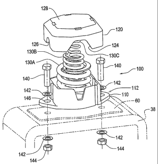
described with reference to Figs. 3-8. Side bearing assembly 100 has a major
longitudinal
axis coincident with the longitudinal axis of a railway car. That is, when the
side bearing is
mounted on railway truck bolster 38 (only partially shown in Fig. 4), the
major axis of the
side bearing is perpendicular to the longitudinal axis of the bolster. Side
bearing assembly
100 includes as main components, a base 110, a cap 120, and one or more
resilient urging
elements 130, such as a spring or elastomer element. In the exemplary
embodiment shown,
there are provided three springs, outer spring 130A, middle spring 130B and
inner spring
130C that serve as the urging element, each of which may have a different
spring constant to
provide an overall combined load rating.
[0044] Base 110 is fixed to bolster 38 by suitable means. As shown, base 110
is
bolted to bolster 38 by way of mounting bolts 140, washers 142 and mounting
nuts 144
passing through mounting holes 146 provided on base flanges 112.
Alternatively, base 110
could be riveted in place. Then, preferably, base 110 is not welded to bolster
38 along at
least transverse sides.
[0045] As best shown in Figs. 4-5, base 110 has opposing side walls 116 and
front
and rear walls 118. Each of the front and rear walls 118 include a large,
generally V-shaped
opening 114. Opening 114 serves as a viewing window allowing visual inspection
of the
springs 130A-C during use of the side bearing. Opening 114 also serves to
reduce weight of
the base 110.
[0046] To increase the travel length of the side bearing, walls 116, 118 are
reduced
in total height by 5/16" from prior designs, such as that used in U.S. Patent
No. 3,748,`001.
CA 02489162 2004-12-07
WO 2004/087478 PCT/US2004/009025
6
This helps to achieve greater travel of the spring before cap 120 and.base 110
mate and
prevent further travel. In an exemplary embodiment, base 110 has a total
height of 3.312"
(+/- 0.030), with walls 116, 118 extending approximately 2.812" above flange
112.
[0047] Referring to Figs. 6-8, cap 120 is cup-shaped and includes downwardly
extending side walls 121, and downwardly extending front and rear walls 122
that surround
base 110 in a telescoping fashion. Front and rear walls 122 are provided with
a large,
generally inverted V-shaped notch 124 corresponding in location with opening
114 on base
110 to assist in forming the viewing window. Side walls 121 also include a
notch 126. The
downwardly extending walls 121, 122 of cap 120 overlap base 110 in such a
fashion that
even when the spring(s) 130 are at their free height or in an uncompressed
condition, there is
still provided an amount of overlap between walls 121, 122 and walls 116, 118.
This
eliminates the need for a retaining pin to prevent separation of the cap
relative to the base.
[0048] Cap 120 is further provided with a top contact surface 128, lower stop
surface 123, and lower recessed spring support surface 127. Preferably, all
peripheral edges
129 are coped. This serves several purposes. It reduces weight of the cap.
Moreover, by
coping the corners, there is a better contact surface is made that abuts
against a car body wear
plate (unshown but located on the underside of a car body immediately above
cap 120 in
use). In particular, by having coped corners, it has been found that less
gouging occurs on the
car body wear plate when the cap slides and rotates in frictional engagement
with the car
body wear plate during use. To further assist in a better contact surface, top
contact surface
128 is formed substantially flat, preferably within 0.010" concave or 0.030"
convex to further
improve wear characteristics. In particular, this bias reduces the chance of
the edge "binding"
against the wear plate and is easier to manufacture.
[0049] To assist in providing long travel of the springs, cap 120 is shortened
similar
to that of base 110. In an exemplary embodiment, cap 120 is shorten-ed in
height by 5/16"
over previous designs to allow further travel of spring(s) 130 before cap 120
and base 110
mate and prevent further travel. Cap 120 preferably has a total cap height of
3.50", with side
walls 121 and 122 extending downward approximately 2.88" below lower support
surface
127. This allows the cap to. overlap farther onto base 110 before sides 121,
.122 hit flange
112.
[0050] As mentioned, the inventive side bearing cap 12U and base 110 can be
used
with one or more urging members, such as springs 130. To achieve long travel
of at least
5/8", it is preferably to reduce the spring solid height from that used in
prior designs. This is
because prior spring designs would have gone solid before 5/8" of travel was
achieved. That
CA 02489162 2004-12-07
WO 2004/087478 PCT/US2004/009025
7
is, the individual spring coils would have compressed against each other so
that no further
compression was possible.
[0051] Many exemplary spring configurations were designed and tested. Suitable
exemplary versions are provided in table form in Fig. 18. Each of these are
capable of travel
during use of at least 5/8" (0.625"). That is, each have a travel from a
loaded height (such as
4.44") to a fully compressed height (such as 3.68") where the spring is fully
compressed or
the cap and base mate that equals or exceeds 5/8" of travel.
[0052] Although three springs per side bearing are described in many
embodiments,
the invention in not limited to this and fewer, or even more, springs could be
used. In fact,
the number and size of springs may be tailored for a particular application.
For example,
lighter cars will use a softer spring rate and may use softer springs or fewer
springs.
Similarly, multi-unit articulated cars may use lighter or fewer springs
because such cars use
four side bearings instead of two per car. As such, the load carrying capacity
of each can be
reduced. Also, it has been found that better performance can be achieved
through use of
substantially softer spring constants than previously used. This has been
found to provide a
suspension system with a slower reaction time, which has been found to achieve
improved
tracking and curving, without adversely affecting hunting. This also has been
found to result
in reduced sensitivity to set-up height variations or component tolerances so
as to achieve a
more consistent preload on the truck system. This tends to equalize the
loading and allow a
railcar to stay more level , with less lean or roll both statically and
dynamically.
[0053] To obtain longer fatigue life, the material used for base 110 and cap
120 has
been changed from Grade C steel to Grade E steel, which is harder and
stronger. To assist in
longer service life, hardened wear surfaces are provided on the outside
surfaces of base walls
116.
[0054] Additionally, in an exemplary preferred embodiment, to prevent
excessive
movements and accelerated wear, reduced longitudinal clearances between cap
120 and base
110 are provided by reducing the tolerances from prior values. This can be
achieved, for
example, by more closely controlling the casting or other formation process of
the cap 120
and base 110 side walls. In a preferred embodiment, base 110 has a
longitudinal distance of
7.000" (+0.0051-0.015) between outside surfaces of-side walls 116 and internal
surfaces of
side walls 122 of cap 120 have a longitudinal distance of 7.031" (+0.000/-
0.020). This
results in a closely controlled combined longitudinal spatial gap having a
minimum of 0.006"
and a maximum of 0.046." The minimum is achieved when-base side walls 116 are
at the
maximum tolerance of 7.005" and the cap side walls 122 are at. the minimum
tolerance of
CA 02489162 2004-12-07
WO 2004/087478 PCT/US2004/009025
8
7.011." The maximum is achieved when the base side walls 116 are at the
minimum
tolerance of 6.985" and the cap side walls 122 are at the maximum tolerance of
7.031."
[0055] Also, it is important to keep the distance from top surface 128 to
lower stop
surface 123 at 1.125" (+/-0.030) so as to ensure travel of at least 5/8"
before full compression
of cap 120 on base 110.
[0056] Because of the possibility of various spring combinations, it is
desirable to
provide a safety feature that prevents interchangeability of improper
components for a given
application. To achieve this, exemplary embodiments provide keying features on
both the
cap 120 and base 110 to prevent mismatch of components. Also, caps 120 can be
provided
with spring lockout features that prevent improper combinations of springs to
be used.
[0057] Figures 9-10 show a first exemplary embodiment in which all three
springs
130A, 130B and 130C are used. This application would be used for heavier
railcars and can
use any of the three-spring combinations listed in Figure 18. However, a
preferred
combination of springs is the bottom example in Figure 18. Use of a three-
spring
combination is particularly suitable for railcars in excess of 50,000 lbs,
typically between
50,0001bs and 110,000 lbs. Such cars are often boxcars, steel coal cars, multi-
level auto rack
cars and the like.
[0058] This configuration includes a first keying feature configuration
consisting of
vertical half-circle recessed keying features 150 provided on opposite
diagonal outside
corners of base 110 and corresponding vertical half-circle protruding keying
features 160
provided on corresponding inside corners of cap 120. With tllese keying
features, base and
caps for only this application will be allowed to mate and overlap. This
prevents
mismatching of components. Moreover, the keying features 150, 160 preferably
prevent
improper orientation of components. For example, the keying feature should
preferably not
prevent use of a proper cap, but rotated 180' from a correct orientation.
[0059] Figures 11-12 show a second exemplary embodiment in which only the two
heavier springs 130A and 130B are used. This application would be used for
medium weight
railcars and can use any of the different outer and middle springs listed in
Figure 18. This
combination of springs is particularly suited for railcars weighing between
about 40,000 lbs.
to 65,0001bs.
[0060] This configuration includes a second keying feature configuration
consisting
of vertical half-circle recessed keying features 150 provided on different
opposite diagonal
outside corners of base 110 and corresponding vertical half-circle protruding
keying features
160 provided on corresponding inside corners of cap 120. With these keying
features, base
CA 02489162 2004-12-07
WO 2004/087478 PCT/US2004/009025
9
and caps for only this application will be allowed to mate and overlap. This
prevents
mismatching of components. For example, even if rotated, cap 120 for this
embodiment will
not mate with the base of the previous embodiment.
[0061] Figures 13-14 show a third exemplary embodiment in which only springs
130A and 130C are used. This application would be used for lighter railcars or
multi-unit
railcars and can use any of the different outer and inner spring combinations
listed in Figure
18. This combination of springs is particularly suited for use with railcars
weighing less than
about 45,000 lbs. It is also suited for use in center trucks of articulated
cars, which use four
side bearings per truck rather than the standard two. Because there are twice
as many side
bearings, the spring rate can be lower for each side bearing.
[0062] This configuration includes a first keying feature configuration
consisting of
vertical half-circle recessed keying features 150 provided on same-side
opposite outside
corners of base 110 and corresponding vertical half-circle protruding keying
features 160
provided on corresponding inside corners of cap 120. With these keying
features, base and
caps for only this application will be allowed to mate and-overlap. This
prevents
mismatching of components. For example, cap 120 of this embodiment will not
fit on either
of the previous two embodiments.
[0063] The use of the above keying features 150, 160 achieve proper matching
of
base and cap components. However, additional features are needed to ensure
that the proper
spring combinations are used for a particular application. The enibodiment of
Figures 9-10
uses all three springs. Because of this, there is no need for a spring lockout
feature. As such,
the underside of cap 120 in this embodiment will appear as in Figure 8.
However, in the
Figures 11-12 embodiment, only the two outer springs 130A and 130B are used.
To prevent
usage of spring 13 C, lower recessed spring support surface 127 of 'cap 120 in
Figure 15 is
provided with a suitable spring lockout feature 170 that prevents insertion of
an improper
spring. In this case, spring lockout feature 170 may be a boss that protrudes
downwardly and
is sized to prevent use of small spring 130C, but is sized to not interfere
with placement of
springs 130A or 130B against spring support surface 127 on the interior of cap
120.
Similarly, in the Figures 13-14 embodiment, lower recessed spring support
surface 127 of cap
120 in Figure 16 is provided with a second, exemplary spring lockout feature
170 that
protrudes downwardly and prevents use of middle spring 130B, without
interfering with
placement of springs 130A or 130C. Other configurations of a spring lockout
feature 170 are
contemplated. For example, if only outer spring 130A was desired to be used, a
third
exemplary spring lockout feature 170 could be provided as in Figure 17 to
prevent use of
CA 02489162 2004-12-07
WO 2004/087478 PCT/US2004/009025
both the inner and middle springs 130B and 130C. Thus, the combination of base
and cap
keying features 150, 160 and the spring lockout features 170 prevent
interchanging of
improper components for a particular application.
[0064) Additional advantages are achieved by use of specific spring constants
in the
inventive side bearing. Prior three-spring designs had dramatically higher
spring constants,
which were believed to be necessary to achieve proper load support and -
cushion to the
railcar. For example, for a 65,000 lb. railcar many prior designs had a
combined load rate of
about 7100 lb/in (3705 lb/in for the outer spring, 2134 lb/in for the middle
spring, and 1261
lb/in for the inner spring). The top example in Figure 18 falls into this
category. However, it
has been found that substantially improved ride and load balancing
characteristics can be
achieved by dramatically reducing the load rate of the springs, in effect
making them much
softer. Many benefits can be achieved if the combined load rate is between
about 4,000-
6,000 lbs/in. If the rate is lowered much below 4,000 lb/in, it is possible
that the side bearing
will disengage from contact with the bottom of the car body, which is
undesirable. As the
load rate increases towards 6,000 lb/in, similar benefits can be achieved.
However, the
higher in this range, the more sensitive the springs are to manufacturing
tolerance and set-up
deviations.
[0065] A preferred embodiment according to the invention is shown at the
bottom
of Figure 18 and uses a total combined load rate of about 4506 lb/in (2483
lb/in for the outer
spring, 1525 lb/in for the middle spring, and 498 lb/in for the inner spring).
A spring
combination near the bottom of the preferred range of 4,000-6,000 lb/in. has
been found
particularly suitable for several reasons. First, it allows the side bearing
to become less
sensitive to set-up height variations and tolerances. That is, small
deviations from one side
bearing to another on a truck have been found to have little effect on the
achieved preload.
Thus, a spring with this range of preload has been found to be capable of a
more consistent
preload from side bearing to side bearing, even if there are minor set-up
height or other
tolerance variations or non-uniformities. This tends to equalize the loading
and allow a
railcar to stay more level, with less lean or roll both statically and
dynamically. Second, such
lowered rates provide a suspension system with a slower reaction time, which
has been found
to achieve improved tracking and curving, without adversely affecting hunting.
However, as
mentioned, increased spring rates approaching 6,0001b/in. can be used.
However, to achieve
similar performance, various design tolerances must be more tightly
controlled, because as
the spring rate increases towards 6,0001b/in., the sensitivity to set-up and
tolerance variances
increases. Thus, without appropriate control of these tolerances, such
deviations may result
CA 02489162 2004-12-07
WO 2004/087478 PCT/US2004/009025
11
in unlevel loading, resulting in undesirable lean of the car body from a flat
state if one side
bearing on the truck is not set-up the same as the other.
[0066] This combination of features has also achieved great weight reduction
from
prior designs. For example, the exemplary side bearing 100 has been found to
have a weight
of only 47.3 pounds, which is down from 55.9 pounds of prior designs.
[0067] While only specific embodiments of the invention have been described
and
shown, it is apparent that various alternatives and modifications can be made
thereto. Those
skilled in the art will also recognize that certain additions can be made in
these illustrative
embodiments. It is, therefore, the intention in the appended claims to nover
all such
alternatives, modifications and additions as may fall within the true scope of
the invention.
.. j~