Note: Descriptions are shown in the official language in which they were submitted.
CA 02489219 2004-12-03
MULTI-PLY LINEAR DRAW SUPPORT POST
FIELD OF THE INVENTION
The present invention relates to support posts for use in packaging an'
object or group of objects in a carton or the like, the support posts being
used for
supporting axial loads imposed on the carton, and optionally providing lateral
cushioning or protection as well, such as at corners of a packaged object. The
invention relates in particular to such support posts formed as tubular
structures
from paperboard materials.
BACKGROUND OF THE INVENTION
When packaging one or more objects in a carton or other package that itself
does not provide sufficient strength for supporting axial loads and/or for
cushioning the objects) against lateral impacts, particularly at the corners,
it is
known to include support posts and/or corner protectors in the package to
provide
the needed axial load support and/or lateral impact protection. Such support
posts
or corner protectors are commonly made from paperboard materials One known
type of corner protector or support post is formed by convolutely winding a
sheet
of paperboard for a plurality of turns about a mandrel and adhering the
adjacent
windings together to form a multi-layer tube. The tube while still wet can be
deformed into a desired cross-sectional shape and allowed to dry and set.
U.S. Patent No. 6,186,329 describes a mufti-grade convolutely wound
corner protector. The corner protector is formed by first preparing a
paperboard
sheet from three separate pieces of paperboard of different grades. In
particular, a
first piece of paperboard of relatively higher grade (i.e., higher density and
higher
stiffness for a given thickness) is joined at one edge to the edge of a second
piece
of paperboard of relatively lower grade (i.e., lower density and lower
stiffness for a
-1-
CA 02489219 2004-12-03
given thickness). An opposite edge of the second piece is joined to a third
piece of
paperboard of higher grade. The paperboard sheet is convolutely wound about a
mandrel to build up a plurality of layers or turns, which layers are adhered
together. The resulting tube has a wall made up of at least three layers at
any given
circumferential location, wherein inner and outer layers comprise the higher-
grade
paperboard and one or more intermediate layers comprise the lower-grade
paperboard.
The process of the'329 patent, while effective for producing mufti-grade
tube structures, is necessarily a batch type of process wherein a single tube
is made
at a time; the batch process is inherently inefficient, particularly in view
of the
requirement of preparing the starting sheet from three separate pieces of
paperboard. The process would be even less efficient if it were used to
produce
tubes having more-complicated ply arrangements, such as high/low/high/low/high
grade, for example.
SUMMARY OF THE INVENTION
The present invention addresses the above needs and achieves other
advantages, by providing a mufti-ply support post and a method of making multi-
ply support posts using a continuous type of production process. In accordance
with one embodiment of the invention, there is provided a method for making a
mufti-ply support post, comprising the steps of
providing a mandrel that extends along an axis;
advancing an inner paperboard ply parallel to the axis of the mandrel while
wrapping the inner ply about the mandrel such that opposite side edges of the
inner
ply are proximate each other and are parallel to the axis of the mandrel;
advancing from one to a plurality of intermediate paperboard plies parallel
to the axis of the mandrel while wrapping the or each intermediate ply about
the
mandrel such that opposite side edges of the or each intermediate ply are
proximate
each other and are parallel to the axis of the mandrel;
advancing an outer paperboard ply parallel to the axis of the mandrel while
wrapping the outer ply about the mandrel such that opposite side edges of the
outer
ply are proximate each other and are parallel to the axis of the mandrel; and
-2-
CA 02489219 2004-12-03
joining the inner, intermediate, and outer plies together with adhesive to
form a tube on the mandrel, the tube being drawn linearly along the mandrel;
wherein the inner and outer plies comprise relatively higher-grade
paperboard, and at least one intermediate ply comprises a relatively low-grade
paperboard.
Thus, the tube is formed continuously on the mandrel and is drawn linearly
along the mandrel. At a downstream station, the tube can be cut into desired
lengths. The tubes can then be allowed to sit for a period of time to set the
adhesive; the setting process can be hastened by heating the tubes in an oven
or the
like, if desired; the resulting tubes thus have the same cross-sectional shape
as the
mandrel on which they were formed. Alternatively, while the tubes are still
wet,
the tubes can be deformed to a different cross-sectional shape (e.g., a
generally L-
shaped configuration, in the case where the tubes are to be used as corner
protectors) and can then be allowed or caused to set. The continuous
production
process is more-efficient than the batch process used in convolute winding,
and
also allows substantial freedom in arranging various numbers and grades of
plies in
various orders in the tube wall.
In some embodiments of the invention, a plurality of intermediate low-
grade plies can be included in the tube wall. The low-grade plies can all be
contiguous, or alternatively can be separated by intervening higher-grade
plies.
The inclusion of lower-grade paperboard material in the tube wall allows
the cost of the support post to be reduced. At the same time, the bending
stiffness
of the tube is not substantially compromised because the lower-grade
paperboard
material is located in the middle of the tube wall, whereas the primary
contributors
(o bending stiffness are the higher-grade plies located inwardly and outwardly
of
the low-grade ply ar plies.
In another embodiment of the invention, a linear draw support post
comprises a plurality of separate paperboard plies wrapped one upon another
about
an axis and adhered together to form a tube, wherein opposite edges of each
ply
extend parallel to the axis, and wherein at least one ply located radially
between
two other plies is embossed with a plurality of discrete embossments spaced
apart
-3-
CA 02489219 2004-12-03
along length and width directions of the ply for increasing an effective
caliper of
the ply. The embossments increase the effective caliper of the ply in the tube
wall;
as a result, the plies on opposite sides of the embossed ply are spaced
farther apart,
without substantially increasing the mass of the embossed ply relative to a
non-
S embossed ply. The increased spacing between the inner and outer plies
contributes
to an increase in bending stiffness of the tube, which leads to an increased
resistance to buckling of the tube under axial loads; and increased side wall
compressive stiffness. The embossed ply can be of the same grade as the other
plies in the tube, or can be a relatively lower grade than other plies.
BRIEF DESCRIPTION OF THE SEVERAL VIEWS OF THE DRAWINGS)
Having thus described the invention in general terms, reference will now be
made to the accompanying drawings, which are not necessarily drawn to scale,
and
wherein:
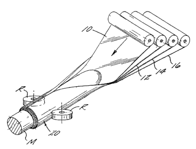
FIG. 1 is a schematic depiction of an apparatus and process for making a
multi-grade linear draw support post in accordance with one embodiment of the
invention;
FIG. 2 is a fragmentary cross-sectional view through a support po$t formed
by the process of FIG. 1;
FIG. 3 shows a corner protector in accordance with an embodiment of the
invention;
FIG. 4 illustrates an embossed ply for incorporation into a support post in
accordance with the invention;
FIG. 5 shows a cross-sectional view through a support post in accordance
with another embodiment of the invention, having a central embossed ply;
FIG. 6 is a diagrammatic depiction of a process for embossing a ply in
accordance with the invention;
-4-
CA 02489219 2004-12-03
FIG. 7 is a cross-sectional view through a support post in accordance with
yet another embodiment of the invention, having two embossed plies separated
by
an intervening non-embossed ply;
FIG. 8 is a cross-sectional view through a support post in accordance with a
S further embodiment of the invention, wherein a corrugated ply is included in
the
wall of the post;
FIG. 9 is a cross-sectional view through a support post in accordance with
another embodiment of the invention, having two corrugated plies separated by
an
intervening non-corrugated ply;
FIG. 10 depicts an apparatus and process for making a multi-grade linear
draw support post in accordance with another embodiment of the invention,
having
a narrow reinforcing ply; and
FIG. 11 is a cross-sectional view of a support post produced in accordance
with the process of FIG. 10.
DETAILED DESCRIPTION OF THE INVENTION
The present inventions now will be described more fully hereinafter with
reference to the accompanying drawings, in which some, but not all embodiments
of the invention are shown. Indeed, these inventions may be embodied in many
different forms and should not be construed as limited to the embodiments set
forth
herein; rather, these embodiments are provided so that this disclosure will
satisfy
applicable legal requirements. Like numbers refer to like elements throughout.
An apparatus and process for making a multi-grade linear draw support
post in accordance with one embodiment of the invention is shown in FIG. 1.
The
apparatus includes a mandrel M that extends along an axis and has a
substantially
constant cross-sectional size and shape over most of its length. The mandrel
can
have a circular cross-section, as shown, or can have a non-circular cross-
section.
The apparatus also includes a tube-conveying arrangement, such as a pair of
opposed rollers R (or other rotary devices such as belts, etc.) for
frictionally
-5-
CA 02489219 2004-12-03
engaging opposite sides of a tube being formed on the mandrel, such that
operation
of the tube-conveying arrangement causes the tube to be linearly drawn along
the
mandrel. As the tube is drawn along the mandrel, the various plies of which
the
tube is constructed are drawn from their respective supply rolls, as shown.
The
apparatus also includes a wrapping arrangement (not shown), such as a plow or
the
like, that is operable to manipulate each ply so as to wrap the ply about the
mandrel, or about the ply or plies already wrapped 'about the mandrel. The
apparatus further includes adhesive applicators (not shown) for applying
adhesive
to the confronting surfaces of adjacent plies before the plies are wrapped one
upon
another about the mandrel. Such adhesive applicators are known in the art.
Thus, in the illustrated example in FIG. 1, and as shown in greater detail in
FIG. 2, a tube 20 is formed from four plies 10, 12, 14,16 each drawn from its
own
respective supply roll. Each ply has a width approximately equal to the
curvilinear
distance (i.e., the mandrel circumference, in the case of a circular mandrel
as
shown) about the outer surface of the mandrel M, so that the width of the ply
wraps
substantially fully about the mandrel. The opposite side edges of each ply
extend
parallel to the axis of the mandrel and are proximate each other; the edges
may
form a butt joint, or there may be a small gap or a small overlap
therebetween.
Preferably the edges of adjacent plies are circumferentially staggered
relative to
each other so that the ply joints are not aligned with each other, as shown
for plies
12 and 14 in FIG. 2.
Paper is available in a wide variety of grades. In general, paper stiffness
(for a given thickness) can be improved by mechanical refining of paperboard
pulps. Thus, a well-beaten pulp generally produces a stiffer grade of paper
compared to a lightly beaten pulp, at the same thickness. In addition, paper
'stiffness can be improved by compressing the paperboard during manufacture by
running the web through a set of high-pressure nip rolls. Further, paperboard
stiffness is influenced by fiber type and quality. As a general rule, stiffer
paperboard sheets have a higher density than less-stiff paperboard sheets, at
the
same thickness. Stated differently, the above treatments generally result in
an
increase in paperboard density along with the increase in paperboard
stiffness. The
higher-density, higher-stiffness papers are also more costly.
-6-
CA 02489219 2004-12-03
In accordance with the invention, the inner ply 10 and the outer ply 16
comprise paperboard of relatively high sriffness and high density, also
referred to
as' high-grade~paperboard. Through theoretical calculations and empirical
testing,
it can be shown that the lengthwise bending stiffness of a multi-layer tube is
largely a function of two factors, namely, the stiffness of the ply or plies
nearest
the firmer and outer surfaces of the tube, and the radial spacing between
these plies.
The stiffness of the plies, for a given thickness, correlates with the
paperboard
grade; thus, a given ply of high-grade paperboard has a greater stiffness than
an
otherwise equivalent ply of lower-grade paperboard. Placing high-grade plies
toward the inside and outside of a tube tends to maximize the contribution
these
plies make toward the bending stiffness of the tube.
On the other hand, the stiffness of the intermediate plies in the middle of
the tube wall tends to contribute only weakly toward the overall bending
stiffness
of the tube, but these plies do serve the important function of spacing the
high-
grade inner and outer plies apart from each other. The intermediate plies thus
are
roughly analogous to the web of an I-beam, which spaces apart the two flanges
that
contribute most of the bending stiffness of the beam. All other things being
equal,
the farther apart the inner and outer plies are spaced, the greater will be
the
bending stiffness of the tube. Accordingly, in accordance with the invention,
one
or more of the intermediate plies are selected to be lower-grade paperboard;
since
the contribution these plies make to the tube's stiffness is relatively slight
compared with the inner and outer plies' contributions.
Thus, one or both of the intermediate plies 12 and 14 comprise paperboard
of relatively lower stiffness and density, i.e., low-grade paperboard. The
usage of
such low-grade paperboard in the middle of the tube wall does not
substantially
impair the bending stiffness of the tube, relative to a tube formed entirely
of
higher-grade paperboard, and can result in significant cost savings.
The tube 20, once formed on the mandrel M, is linearly advanced along the
mandrel to a downstream cutting station (not shown), where the tube is cut
into
desired lengths. The resulting tubes can then be held to allow the adhesive to
set,
such that the tubes have the same shape as when they were removed from the
-
CA 02489219 2004-12-03
mandrel. The tubes can be used as support posts in a package for carrying
axial
loads exerted on the package, such as when multiple packages are stacked upon
one another.
Alternatively, after the tubes have been cut into lengths, or during the
S cutting process, and while the adhesive is still wet, the tubes can be
deformed into
a different cross-sectional shape and then allowed to dry. As an example, FIG.
3
shows a tube 20' deformed into a generally L-shaped cross-section, for use as
a
support post and corner protector in a carton C to support axial loads as well
as to
protect the corner of a packaged object O. The formation and uses of such
corner
protectors are described in U.S. Patent No. 6,186,329, incorporated herein by
reference, and hence are not further described herein.
The invention is not limited to four-ply support posts, nor is it limited to
posts having only one high-grade ply radially inward and radially outward of
the
intermediate low-grade ply or plies. Support posts in accordance with the
invention can have from one to a plurality of high-grade plies located
radially
inward of the low-grade ply or plies, and can have from one to a plurality of
high-
grade plies located radially outward of the low-grade ply or plies. As noted,
one or
more intermediate low-grade plies can be included. When a plurality of low-
grade
plies are included, such plies can all be contiguous, or alternatively there
can be
intervening high-grade plies between them.
In another aspect of the invention, the radial spacing between inner and
outer plies in a support post can be enhanced with virtually no addition of
mass to
the support post, by embossing one or more of the intermediate plies. FIG. 4
shows one example of an embossed ply 30 having a plurality of discrete
embossments 32 that project from one side of the ply. As used herein, the term
"emboss" denotes a process wherein a localized region of the ply is forced to
deform into a recess or depression in a surface of a tool such as a die or
roller such
that the deformation remains a8er the deforming force is removed; "embossment"
denotes the localized deformed region of the ply so made. The embossments are
spaced apart along two orthogonal directions (and therefore spaced apart along
both length and width directions of the ply). The embossments can have various
_g_
CA 02489219 2004-12-03
shapes, such as truncated cones (as shown), truncated pyramids, ete. Embossing
is
generally carried out by deforming the ply while the ply is wet or moist and
the ply
is then dried, as further described below. The embossments act as spacers that
abut
an adjacent ply; as long as the embossments are not spaced too far apart, the
adj acent ply will stand off from the regions of the embossed ply located
between
the embossments, and thus void spaces will exist between the embossed ply and
the adjacent ply. When the embossed ply is incorporated into a support post,
therefore, the middle of the tube wall will have void spaces and thus will
have a
lower density that it otherwise would have. The effective caliper of the
embossed
ply is greater than an equivalent non-embossed ply, and hence the plies on
either
side of the embossed ply are spaced farther apart than they otherwise would
be. As
a result, the bending stiffness of the support post can be enhanced.
FIG. 5 shows an example of a support post 40 having a total of five plies,
including an inner ply 42, three intermediate plies 44, 46, 48, and an outer
ply 50.
The middle ply 46 is embossed; in this case, the embossments project from both
sides of the ply, as opposed to the single-sided embossing in FIG. 4. The five
plies
can all be of the same grade of paperboard, or can be of different grades. In
one
embodiment, the embossed ply 46 can be a relatively low-grade paperboard while
the rest of the plies are relatively higher in stiffness. In another
embodiment, all of
the intermediate plies 44, 46, and 48 can be relatively low in stiffness while
the
inner ply 42 and outer ply 50 are relatively higher in stiffness. .
A paperboard ply can be embossed using a process diagrammatically
represented in FIG. 6. The ply 30 is first moistened in a moistening unit 60
to
loosen the fiber bonds. The moistened ply is passed through an embosser 62,
which may comprise a pair of opposed embossing rolls 64, 66 that form a nip
through which the moistened ply is passed. The roll 64 defines a plurality of
recesses or depressions in its outer surface, and the roll 66 has a plurality
of
corresponding projections that are in registration with the depressions in the
roll 64
and are configured to deform localized regions of the moistened ply into the
depressions in the roll 64. After exiting the embosser, the ply is dried in a
dryer
68. It is possible to omit the moistening step if the ply is embossed while
still wet
during the process of producing the paperboard on the paper making machine.
-9-
CA 02489219 2004-12-03
As noted, the invention is not limited to support posts having a single
embossed ply. FIG. 7 shows an alternative embodiment of a tube 70 having two
embossed plies and four unembossed plies. More particularly, the tube wall has
a
radially miler region made up of two adjacent unembossed plies 72, 74. A
radially
intermediate region of the tube wall is made up of three plies, which comprise
an
inner embossed ply 76 that is adjacent the ply 74, a middle unembossed ply 78
immediately outward of and contiguous with the inner embossed ply 76, and an
outer embossed ply 80 immediately outward of and contiguous with the ply 78.
An outermost unembossed ply 82 is wrapped about the outer embossed ply 80.
Thus, each embossed ply is sandwiched between two unembossed plies. Various
combinations of paperboard grades can be used for the different plies in the
tube.
In the practice of the invention, a ply can be drawn from a supply roll as an
ordinary unembossed ply and can be embossed using a process similar to that
shown in FIG. 6 as the ply is being advanced to the mandrel M. Alternatively,
an
embossed ply could be prepared beforehand and could be supplied in the form of
a
roll of embossed material, such that the embossed ply would simply be drawn
from
the supply roll and advanced to the mandrel.
Embossing is not the only way that can be used, in accordance with the
invention, to "artificially" increase the effective thickness of intermediate
plies in a
support post. A similar result can be achieved by corrugating one or more
plies.
To maximize the axial stiffness of the ply or plies, the corrugations or
flutes should
extend parallel to the axis of the post. FIG. 8 shows one embodiment of a
support
post having an inner ply 142, three intermediate plies 144, 146,148, and an
outer
ply 150. The middle ply 146 is corrugated, with the flutes extending parallel
to the
axis of the post (perpendicular to the plane of the figure), and actually
comprises a
double-faced corrugated board in which a corrugated layer is adhered on its
opposite faces to non-corrugated paperboard layers. The double-faced
corrugated
board can be prepared in advance and supplied in roll form, although it is
also
possible to form it in-line during the manufacture of the linear draw support
post.
The various plies can all be of the same grade of paperboard, or can be of
different
grades. In one embodiment, the corrugated ply 146 can be a relatively low-
grade
paperboard while the rest of the plies are relatively higher in stiffness. In
another
-10-
CA 02489219 2004-12-03
embodiment, all of the intermediate plies 144,146, and 148 can be relatively
low
in stiffness while the inner ply 142 and outer ply 150 are relatively higher
in
stiffness.
FIG. 9 depicts another embodiment of a support post 170 having two
corrugated plies and four non-corrugated plies. More particularly, the tube
wall
has a radially inner region made up of two adjacent non-corrugated plies
172,174,
A radially intermediate region of the tube wall is made up of three plies,
which
comprise an inner corrugated ply 176 that is adjacent the ply 174, a middle
non-
corrugated ply 178 immediately outward of and contiguous with the inner
corrugated ply 176, and an outer corrugated ply 180 immediately outward of and
contiguous with the ply 178. An outermost non-corrugated ply 182 is wrapped
about the outer corrugated ply 180. Thus, each corrugated ply is sandwiched
between two non-corrugated plies. Various combinations of paperboard grades
can be used for the different plies in the tube. Each of the corrugated plies
can be
pre-adhered to at least one adjacent non-corrugated ply prior to advancing the
plies
to the forming mandrel. For example, the corrugated ply 180 and the adjacent
non-
corrugated ply 178 can be pre-adhered to each other, forming a so-called
single-
faced corrugated board; this board can be drawn from a supply roll (not shown)
of
single-faced board and advanced to the mandrel, or can be prepared in-line.
Likewise, the plies 174 and 176 can form a single-faced board drawn from a
supply roll (not shown) or prepared in-line. Alternatively, the plies 180 and
182
could comprise a single-faced corrugated board, and the plies 174,176, and 178
could comprise a double-faced corrugated board. It is thus possible to
incorporate
various combinations of non-corrugated, corrugated, single-faced, and/or
double-
faced ply arrangements in a post in accordance with the invention.
It is also within the scope of the invention to reinforce one or more
particular regions of a support post wall with one or more paperboard plies
having
a narrower width than the other plies making up the post, so that the region
is
thickened relative to other portions of the wall. FIG. 10 shows an apparatus
and
process for accomplishing this in accordance with one embodiment of the
invention. The process is generally similar to that described in connection
with
FIG. 1. A plurality of plies 210, 212, 213, 214, and 216 are linearly advanced
to
-11-
CA 02489219 2004-12-03
the mandrel M and wrapped around the mandrel. As previously noted in the
discussion of FIG. 1, although the plies are shown as all being aligned in the
circumferential direction about the mandrel, in reality the plies would be
staggered
so that the seams between edges of the plies are not aligned with each other
from
one layer to the next in the resulting tube 220. The ply 213 is substantially
narrower than the other plies, and is located with respect to the Later-form
support
post 220' (FIG. 1 I) so as to thicken and thereby reinforce a particular
region of the
post. For example, as shown in FIG. I I, the narrow ply 213 is located in the
inside
corner region of the post 220' to thicken and reinforce this region. Of
course, more
than one narrow ply can be employed in a given region of a post, or a post can
include more than one reinforced region each having one or more narrow plies
for
reinforcement. A region having one or more narrow reinforcing plies will tend
to
have greater bending stiffness than it would have absent the reinforcing ply
or
plies. Thus, for example, a region of a support post that tends to experience
the
largest bending stresses in use, or a region that inherently is relatively
weak in
bending because of its geometry, can be reinforced with one or more narrow
plies
in accordance with the invention.
Based on the foregoing description, it will be appreciated that the
continuous linear draw production process of the invention is more-efficient
than
the batch convolute winding process used in the prior-art, and also allows
substantial freedom in arranging various numbers and grades of plies in
various
orders in the tube wall. The multi-grade linear draw support posts of the
invention
enable axial load-bearing strength to be substantially maintained while
substituting
a proportion of less-costly low-grade paperboard for the more-costly high-
grade
paperboard that might otherwise be required. Additionally, the linear draw
support
posts having one or more embossed or corrugated plies also allow a reduction
in
the amount of paperboard material required to form a support post. The use of
narrow reinforcing plies in a support post allows specific regions of a post
to be
reinforced for greater bending stiffness and/or cushioning.
Many modifications and other embodiments of the inventions set forth
herein will come to mind to one skilled in the art to which these inventions
pertain
having the benefit of the teachings presented in the foregoing descriptions
and the
-12-
CA 02489219 2004-12-03
associated drawings. Therefore, it is to be understood that the inventions are
not to
be limited to the specific embodiments disclosed and that modifications and
other
embodiments 'are intended to be included within the scope of the appended
claims.
Although specific terms are employed herein, they are used in a generic and
descriptive sense only and not for purposes of limitation.
-13-