Note: Descriptions are shown in the official language in which they were submitted.
CA 02489300 2006-11-14
WO 211114/103336 PCT/1JS21103/01971)9
A VALVE FOR A FILL UP TOOL
BACKGROUND OF THE INVENTION
Field of the Invention
The present invention relates to an apparatus and a method used in the
completion
of a well. More particularly, the invention relates to a casing fill-up and
circulating
tool. More particularly still, the present invention relates to a diaphragm
ball valve
for a casing fill-up and circulating tool.
Description of the Related Art
In the drilling of oil and gas wells, a wellbore is formed using a drill bit
that is urged
downwardly at a lower end of a drill string. After drilling the welibore to a
predetermined depth, the drill string and bit are removed. Thereafter, the
wellbore is
typically lined with a string of steel pipe called casing. The casing provides
support
to the wellbore and facilitates the isolation of certain areas of the wellbore
adjacent
hydrocarbon bearing formations.
During the run-in of a casing string, the string is typically filled with mud.
The
primary reason to fill the casing string with mud is to prevent the new string
of casing
from collapsing due to the pressure imbalances between the inside of the
casing
and the wellbore fluid therearound and avoidance of buoyancy. Typically, the
filling
process occurs as the casing string is assembled at the rig floor. A secondary
reason to fill a casing string with mud is to use the mud to free a casing
string when
the casing becomes stuck during the run-in operation. In this situation, the
drilling
operator circulates mud down the casing to wash sand or other debris from the
lowermost end of the casing, thereby freeing the stuck casing.
Typically, a fill-up and circulating tool is used in conjunction with a mud
pump to fill
and circulate the mud in the casing. An example of a fill-up and circulating
tool is
described in U.S. Patent No. 6,173,777. Figure 1 illustrates a partial
cross-sectional view of a fill-up and circulating tool 50
with a valve 60 in a closed position as shown in the '777 patent.
The tool 50 is supported from a top drive (not shown) and includes a top sub
10 with
an internal bore 12. The internal bore 12 is connected to a mud pump (not
shown)
I
CA 02489300 2004-12-10
WO 2004/003336 PCT/US2003/019709
through a hose (not shown) for filling and circulating a casing 14. The top
sub 10 is
connected to body 16 at thread 18. Tool 50 further includes a rotating sleeve
22
disposed on the upper portion of the body 16. A cup seal 20 is mounted to
sleeve
22. The cup seal 20 is used to seal off the casing 14 when the tool 50 is
operating.
Additionally, a gage ring 38 is mounted on body 16 and secured in place by nut
34.
The gage ring 38 positions the tool 50 in the center of the casing 14 to
facilitate
insertion of the tool 50 into the upper end of the casing 14.
As shown in Figure 1, the body 16 is connected to the valve 60 through a
tubular
spacer 35. The valve 60 includes a valve member 41 (ball valve) that is
movable
between an open and closed position. The valve member 41 is disposed in a
valve
body 40. The valve member 41 is held in position within the valve body 40 by
an
upper valve seal 42, lower valve seal 43, and bottom sub 45. A valve stem 46
and
an arm 44 are attached to valve member 41 to control the open/closed
rotational
position of the valve member 41. As shown, a gage ring 53 is disposed at the
lower
end of the valve body 40. The gage ring 53 centers the valve 60 in the casing
and
protects valve arm 44 during insertion of the valve 60 into the upper end of
the
casing 14. Centering of the valve 60 ensures that the arm 44 will rotate
sufficiently
to open the valve member 41. In the closed position, the arm 44 is
rotationally
limited by its contact with gage ring 53. The arm 44 is constructed and
arranged of
weighted material to open the valve member 41 only when the valve 60 is
inserted
into casing 14 and to close the valve member 41 after the valve is removed
from the
casing 14. The arm 44 is weighted such that upon removal, gravity causes the
arm
44 to rotate downward, thereby providing rotational torque to close the valve
member 41 as the valve 60 is removed from the casing 14.
Figure 2 illustrates a partial cross-sectional view of the prior art fill-up
and circulating
tool 50 with the valve 60 in an open position as shown in the '777 patent. As
depicted, the valve 60 is fully inserted into the upper end of the casing 14.
As the
valve 50 is inserted, the bottom sub 45 will be positioned near the center of
the
casing 14 and gage ring 53 will further center the valve 60. At the same time,
the
valve arm 44 will be rotated by contact with the upper end of the casing 14.
Rotating
the valve arm 44 upwards opens valve member 41. In this position, a mud pump
2
CA 02489300 2004-12-10
WO 2004/003336 PCT/US2003/019709
may be started to fill the casing 14. Fluid from the pump flows through the
bore 12,
through the fully opened valve member 41 and out ports 47 to fill the casing
14.
After the casing 14 is filled, the mud pump is turned off and the tool 50 may
be
removed from the casing 14. Upon removal of the valve 60, gravity causes the
weighted arm 44 to rotate downward, thereby rotating the valve member 41 to
the
closed position as shown on Figure 1. In this manner, the casing 14 is filled
with
mud.
Generally, the mud pump is turned off while the fill-up and circulating tool
is still in
the casing, thereby allowing all the mud in the mud pump and the connecting
hose
to flow through the tool into the casing. However, a problem associated with
the
above referenced fill-up and circulating tool arises when the tool is suddenly
or
accidentally removed from the casing prior to shutting down of the mud pump.
In
this situation, a pressure surge is created in the tool due to the closed
valve, thereby
causing the mud pump to stop. This pressure surge may cause premature failure
of
the mud pump or other hydraulic components. Another problem arises after the
casing is filled with mud. Typically, the tool is pulled out of the casing and
the valve
arm drops down to close the valve member. However, if the mud pump is not
properly turned off to allow the mud in the in the connecting hose to exit the
tool
prior to removal of the tool from the casing, the volume of mud continues to
enter the
tool. Because the valve member is closed, the mud is prevented from exiting
the
tool. As a result, the pressure in the tool may become so large as to cause
the hose
to burst, thereby causing damage to the equipment or injury to personnel on
the rig
floor.
There is a need, therefore, for a valve that will prevent a pressure surge in
the mud
system when the tool is accidentally removed from the casing. There is a
further
need for a valve that will permit a volume of mud in the hose to exit the tool
even
though the valve is closed. There is yet a further need for a more reliable
fill-up and
circulating tool.
3
CA 02489300 2004-12-10
WO 2004/003336 PCT/US2003/019709
SUMMARY OF THE INVENTION
The present invention generally relates to a valve for use in an oilfield
tool. The
valve includes a valve body and a valve member disposed in the valve body. The
valve member is movable between an open and closed position. The valve member
includes an aperture therethrough. The valve further includes a pressure
relief
member disposed in the aperture, whereby at a predetermined pressure the
pressure relief member will permit fluid communication.
In another aspect, the invention provides an apparatus to introduce fluid into
a
casing. The apparatus includes a body having a bore therethrough and a valve
disposed in the body for selectively controlling a fluid flow through the
bore. The
valve includes a valve member movable between an open and closed position. The
valve member includes an aperture for providing selective communication
through
the valve in a closed position. The valve further includes a pressure relief
member
disposed in the aperture, whereby at a predetermined pressure the pressure
relief
member will permit fluid communication.
Further, a method for introducing fluid into a tubular is provided. The method
includes the step of locating an apparatus in the tubular. The apparatus
includes a
body having a bore therethrough and a valve disposed in the body for
selectively
controlling a flow fluid through the bore. The valve includes a valve member
and a
pressure relief member disposed in the valve member. The method further
includes
opening the valve in the apparatus, pumping fluid through the apparatus, and
introducing fluid in to the tubular. The method also includes the step of
removing the
apparatus from the tubular.
BRIEF DESCRIPTION OF THE DRAWINGS
So that the manner in which the above recited features of the present
invention, and
other features contemplated and claimed herein, are attained and can be
understood in detail, a more particular description of the invention, briefly
summarized above, may be had by reference to the embodiments thereof which are
illustrated in the appended drawings. It is to be noted, however, that the
appended
4
CA 02489300 2004-12-10
WO 2004/003336 PCT/US2003/019709
drawings illustrate only typical embodiments of this invention and are
therefore not
to be considered limiting of its scope, for the invention may admit to other
equally
effective embodiments.
Figure 1 illustrates a partial cross-sectional view of the prior art fill-up
and circulating
tool of the '777 patent with a valve in a closed position.
Figure 2 illustrates a partial cross-sectional view of the prior art fill-up
and circulating
tool of the '777 patent with the valve in an open position.
Figure 3 illustrates a valve member of the present invention disposed in an
oilfield
tool.
Figure 4 is an enlarged view of the valve member in an open position.
Figure 5 illustrates an enlarged view of the valve member in a closed
position.
Figure 6 illustrates a view of the valve member after the frangible disk
member fails.
DETAILED DESCRIPTION OF THE PREFERRED EMBODIMENT
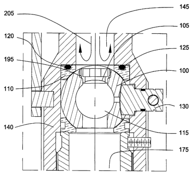
Figure 3 illustrates a valve member 100 of the present invention disposed in
an
oilfield tool. As illustrated, the oilfield tool is a fill-up and circulating
tool 200.
However, it should be noted that the valve member 100 may also be employed in
other hydraulic oilfield tools that require a valve that will prevent
premature failure of
hydraulic components due to pressure surges and pressurization of the tool,
thereby
ensuring the safety of equipment and personnel.
As shown in Figure 3, the tool 200 includes a body 160 that comprises of an
upper
body 140 and a lower body 180. The upper body 140 having an upper bore 145 to
allow fluid communication through the tool 200. Typically, the top portion of
the
upper body 140 is connected to a mud pump (not shown). The mud pump is used
for pumping the mud through the tool 200 into a casing string (not shown). The
mud
pump is typically connected to the tool 200 using a hydraulic hose (not
shown).
5
CA 02489300 2004-12-10
WO 2004/003336 PCT/US2003/019709
As illustrated, the lower body 180 is disposed below the upper body 140. The
lower
body 180 contains a lower bore 175 in fluid communication with the upper bore
145.
The lower bore 175 diverges into one or more ports 185 at the lower end of the
body
180. Additionally, a gage ring 170 is disposed around the lower body 180 to
center
the tool 200 in the casing string.
As depicted on Figure 3, the valve member 100 is disposed between the upper
body
140 and lower body 180. The valve member 100 is housed in a valve body 110.
The valve body 110 is connected to the lower end of the upper body 140. First
and
second seal members 120, 125 are disposed between the upper body 140 and the
valve body 110. The first and second seal members 120, 125 form a sealing
relationship between the upper body 140 and the valve body 110 to prevent
fluid in
the upper bore 145 from flowing around the valve body 110.
In the preferred embodiment, the valve member 100 is a standard ball valve.
However, other forms of valve members may be employed, so long as they are
capable of selectively permitting fluid flow through the tool 200.
Additionally, in the
preferred embodiment, the valve member 100 is constructed from stainless
steel.
However, the valve member 100 may also be constructed from other types of
materials, such as composite material, so long as it is capable of
withstanding a
predetermined pressure and wellbore fluids that may be corrosive.
The valve member 100 is movable between an open and a closed position.
Generally, the open position permits fluid to enter and exit the tool 200
while the
closed position prevents fluid from exiting the tool 200 by sealing a valve
bore 115.
In the open position, the valve bore 115 in the valve member 100 aligns with
the
upper bore 145 and the lower bore 175, thereby allowing fluid communication
through the tool 200. Conversely, in the closed position, the valve member 100
is
rotated approximately 90 degrees. As a result, the valve bore 115 is out of
alignment with the bores 145, 175, thereby preventing the flow of fluid
through the
valve bore 115. In this manner, the valve member 100 selectively controls
fluid
communication through the tool 200.
6
CA 02489300 2004-12-10
WO 2004/003336 PCT/US2003/019709
The valve member 100 further includes an aperture or a lateral bore 195
therethrough to act as a fluid conduit. A pressure relief member or a
frangible disk
member 105 is disposed in the lateral bore 195 to temporality prevent fluid
communication through the lateral bore 195. As shown, the lateral bore 195 is
located perpendicular to the valve bore 115. Therefore, as the valve member
100 is
moved to the closed position, the lateral bore 115 aligns with the upper bore
145
and the lower bore 175. However, the presence of the frangible disk member 105
prevents fluid communication between the upper bore 145 and the lower bore
175.
The frangible disk member 105 is a high-precision component designed to fail
with
the application of a predetermined hydraulic pressure. Typically, the
frangible disk
member 105 is a rupture disk or a diaphragm. Rupture disks are commonly used
in
downhole applications in which the controlled application of pump pressure is
used
to set or operate downhole equipment. In the present invention, the frangible
disk
member is used as a protection device to prevent pressurization of the tool
200. In
doing so the frangible disk member 105 allows fluid communication between the
upper bore 145 and the lower bore 175 when the frangible disk member 105 fails
due to a pressure above the predetermined hydraulic pressure.
The tool 200 further includes a valve stem 130 connected to the valve member
100.
As shown, an arm 135 and a handle 155 are connected to the valve stem 130 on
the
exterior of the tool 200. The handle 155 is constructed and arranged of
weighted
material to open the valve member 100 only when the tool 200 is inserted into
casing and to close the valve member 100 after the tool 200 is removed from
the
casing. The handle 155 is weighted such that upon removal from the casing,
gravity
causes the handle 155 and arm 135 to rotate downward, thereby providing
rotational
torque to close the valve member 100. In this manner the handle 155, arm 135
and
valve stem 130 act as a unit to cause the valve member 100 to move between the
open and closed position during operation of the tool 200.
Figure 4 is an enlarged view of the valve member 100 in the open position. As
shown, the valve bore 115 in the valve member 100 is aligned with the upper
bore
145 and the lower bore 175. As illustrated by arrow 205, fluid from the mud
pump is
permitted to flow down the upper bore 145, through the valve bore 115 and into
the
7
CA 02489300 2004-12-10
WO 2004/003336 PCT/US2003/019709
lower bore 175. As further shown, the first and second seal members 120, 125
on
the valve body 110 prevent any fluid from entering around the valve body 110.
Also
clearly shown is the frangible disk member 105 disposed in the lateral bore
195. It
should be noted that the valve member 100 in the open position does not expose
frangible disk member 105 to the flow of fluid through the valve bore 115.
Figure 5 illustrates a view of the valve member 100 in the closed position. As
depicted, the valve member 100 has rotated approximately 90 degrees to the
closed
position. The valve bore 115 is no longer aligned with the upper bore 145 and
the
lower bore 175. Instead, the lateral bore 195 is aligned with the upper bore
145 and
lower bore 175, thereby exposing the frangible disk member 105 to the fluid in
the
upper bore 145. As illustrated by the flow arrow 205, the fluid in the upper
bore 145
is prevented from entering the lower bore 175. In addition, the sealing
relationship
between the valve body 110 and the upper body 140 prevents any leakage around
the first and second seal members 120, 125.
Typically, the mud pump will be turned off prior to moving the valve member
100 to
the closed position as shown on Figure 5. The excess fluid in the hose
connecting
the mud pump to the tool 200 will either stay in the hose or flow to the tool
200.
Fluid in the tool 200 will usually be at a low pressure because there is no
additional
fluid pressure from mud pump. In this respect, the hydraulic pressure acting
against
the frangible disk member 105 is below the predetermined hydraulic pressure,
thereby allowing the frangible disk member 105 to act as a barrier to fluid
communication into the lower bore 175. Therefore, fluid will collect in the
upper bore
145 and remain there until the valve member 100 is opened. At that time, the
valve
bore 115 will align with the upper bore 145, thereby allowing the fluid to be
communicated to the lower bore 175.
However, if the valve member 100 is intentionally or accidentally closed while
a
volume of mud in the hose continues to be communicated to the tool 200, a
pressure build up will occur in the upper bore 145. As more fluid enters the
upper
bore 145, the hydraulic pressure acting against the frangible disk member 105
will
increase. At a predetermined hydraulic pressure, the frangible disk member 105
is
8
CA 02489300 2004-12-10
WO 2004/003336 PCT/US2003/019709
caused to fail, thereby allowing fluid to enter the lower bore 175 as
illustrated in
Figure 6.
Figure 6 illustrates a view of the valve member 100 after the frangible disk
member
105 fails. As shown, the frangible disk member 105 is no longer disposed
within the
lateral bore 195 but rather is destroyed, thereby removing the barrier between
the
upper bore 145 and the lower bore 175. As illustrated by arrow 205, the
pressurized
fluid inside the upper bore 145 is allowed to flow through the lateral bore
195 into the
lower bore 175 exiting the tool 200 through port 185. In this manner, the
pressure in
the upper bore 145 of the tool 200 may be relieved to prevent damage to the
hose or
the mud pump.
According to another important aspect of the present invention, the destroyed
frangible disk member 105 may be replaced without replacing the valve member
100. In this respect, the valve member 100 may be removed from the valve body
110 to permit the replacement of the frangible disk member 105. The destroyed
frangible disk member 105 is removed and a new frangible disk member 105 is
disposed in lateral bore 195. Thereafter, the original valve member 100 and
the new
frangible disk member 105 are placed back into the valve body 110. In this
manner,
the tool 200 may be quickly put back into operation to continue to fill and
circulate
mud through the casing string.
In operation, the tool 200 is inserted into a string of casing. Upon
installation, the
handle 155 is caused to contact the string of casing and move the valve member
100 from the closed position to the open position. Thereafter, the mud pump is
turned on to introduce fluid into the tool 200 to fill the casing with mud.
The fluid
flows down the upper bore 145, through the valve bore 115 and the lower bore
175,
thereafter exiting out port 185. After the casing is filled, the mud pump is
turned off
and the tool 200 is removed from the casing. Upon removal of the tool 200,
gravity
causes the weighted handle 155 to rotate downward, thereby returning the valve
member 100 to the closed position.
In the event that the tool 200 is removed from the casing prematurely, the
valve
member 100 will close. At this point, fluid will gather in the upper bore 145.
As
9
CA 02489300 2004-12-10
WO 2004/003336 PCT/US2003/019709
more fluid enters the upper bore 145, the hydraulic pressure acting against
the
frangible disk member 105 will increase. At a predetermined hydraulic
pressure, the
frangible disk member 105 is caused to fail, thereby allowing fluid to flow
through the
lateral bore 195. Thereafter, the pressurized fluid inside the upper bore 145
is
permitted to flow through the lateral bore 195 into the lower bore 175 exiting
the tool
200 through port 185. In this manner, the pressure in the upper bore 145 of
the tool
200 may be relieved to prevent damage to the hose or the mud pump.
While the foregoing is directed to embodiments of the present invention, other
and
further embodiments of the invention may be devised without departing from the
basic scope thereof, and the scope thereof is determined by the claims that
follow.