Note: Descriptions are shown in the official language in which they were submitted.
CA 02489340 2004-12-10
WO 03/103507 PCT/US03/18739
HERNIA MESH TACKS
BACKGROUND
This application claims priority from provisional application Serial No.
60/388,119 filed June 11, 2002, all of which is incorporated herein in its
entirety by
reference.
1. Technical Field
The technical field relates to surgical tacks for use in securing mesh during
a
hernia repair procedure and, more particularly, to absorbable surgical tacks
and insertion
instruments.
2. Background of Related Art
During hernia repair surgery it is often necessary to affix a section of mesh
over
the herniated tissue. This is often accomplished through the use of staples or
sutures or
other affixation type means.
One method of affixing mesh to tissue is through the use of surgical screws or
tacks. However, known tacks may have a traumatic distal end which causes
damage to
the hernia mesh and unnecessarily injures the tissue as the tack is being
inserted.
Furthermore, many of these tacks are not configured to be removed after they
have been
implanted in the patient. Thus, it would be desirable to provide an absorbable
hernia tack
capable of a traumatic insertion through mesh and into tissue and having
sufficient tissue
surface bearing area to solidly retain the mesh against the tissue.
It would also be desirable to have a hernia tack which is capable of being
removed by means of the insertion tool.
CA 02489340 2004-12-10
WO 03/103507 PCT/US03/18739
SUMMARY
There are disclosed absorbable hernia tacks suitable for use in securing
hernia
mesh against tissue. The tacks generally include a barrel portion having a
head extending
distally therefrom. The barrel portion and the head define a throughbore for
receipt of a
drive rod of an insertion instrument so that the hernia tack can be driven
through mesh
and into tissue. The throughbore may have various non-circular shapes, such as
D-
shaped, rectangular, polygonal, etc., to increase the drive surface area and
facilitate
insertion in tough tissue. A tissue thread is formed on the barrel portion and
is
configured to engage tissue as the tack is rotated into the tissue. The tissue
thread
includes a leading edge at the distal end of the barrel portion and a trailing
edge at a
proximal end of the barrel portion. The leading edge has the advantage of
following a tip
of an insertion tool to allow a traumatic entry of the tack into tissue.
The head is provided with a drive thread which is configured to engage an
inner
surface of an insertion tool and allow the tack to be moved distally within
the insertion
tool as the drive rod is rotated. The drive thread has a leading edge at its
distal end and a
trailing edge at its proximal end. Preferably these surfaces are chamfered or
rounded off
so as to facilitate engagement with the insertion tool. The throughbore of the
hernia tack
can have various configurations to mate with a drive rod of an insertion tool.
In one
embodiment, the throughbore of the hernia tack has essentially a D-shaped
cross
sectional area. However, other cross sectional areas may be provided for
example, a
rectangular cross section or polygonal cross section.
In various embodiments of the surgical tacks, the proximal and distal surfaces
of
the tissue thread may form various acute or obtuse angles relative to the
barrel portion.
2
CA 02489340 2004-12-10
WO 03/103507 PCT/US03/18739
These angles provide the advantages of increasing the hold of the thread in
tissue and
allowing for easier insertion and/or removal of the tack from tissue.
Alternatively, one or
more of these surfaces may be perpendicular to the barrel portion. It should
be noted that
the drive thread has a substantially greater diameter than the tissue thread
to allow the
head to seat against the mesh without entering the hold in the mesh formed by
the barrel
and tissue thread. The drive thread and the tissue thread are not connected
that is, i.e., are
discontinuous with respect to each other to achieve this advantage.
There is also disclosed an insertion tool for inserting one or more hernia
tacks
through mesh and into tissue. The insertion tool generally includes an
elongated outer
tube which is affixed at its distal end to a handle mechanism. The insertion
tool also
includes an inner drive rod which is rotatably connected to the handle
mechanism. A
pointed tip of the drive rod forms an atraumatic transition with the
atraumatic tip of the
barrel portion to prevent tearing mesh and tissue as the tack is inserted
therethrough.
Various known handle mechanisms may be utilized to rotate the inner drive rod
with
respect to the stationary outer tube. An inner thread may be provided within
the outer
tube so as to engage the drive thread of the head of the hernia tack.
Preferably, the distal
end of the inner thread is flush with the distal end of the outer tube so that
in the event a
tack need be removed, the insertion tool may be positioned over the drive cap
of the tack
and rotated in an opposite direction to draw the tack back into the insertion
tool and
thereby remove the tack from the body.
The inner thread may be provided only at a distal end of the outer tube or may
be
provided throughout the entire length of the outer tube. When the drive thread
is
provided throughout the entire length of the drive tube no biasing spring need
be
3
CA 02489340 2004-12-10
WO 03/103507 PCT/US03/18739
necessary to force additional tacks distally as they are moved distally along
the thread as
the drive rod is rotated. However, in the event the inner thread is only
provided at the
distal end, various other known means may be utilized to bias subsequent tacks
distally
towards the inner thread.
There is also disclosed a display model of any insertion tool and hernia tack
which may be utilized for instructional purposes to demonstrate to surgeons
how the
hernia tack and insertion tools work. This is necessary due to the extremely
small nature
of the tacks which are generally on the border of only a few millimeters in
diameter. The
display model includes a mock outer tube having an inner thread along with a
drive rod
having an end cap. A sample hernia tack is also provided. The outer tube and
head
cap/drive rod are separable to drop the tack into the proximal end of the
model.
Thereafter the D-shaped drive rod is positioned within the D-shaped
throughbore of the
tack and the head cap rotated to rotate the tack out the distal end of the
outer tube.
BRIEF DESCRIPTION OF THE DRAWINGS
Various embodiments are described herein with reference to the drawings
wherein:
FIG. 1 is a perspective view of a first embodiment of a hernia repair tack;
FIG. 2 is a side view of the hernia repair tack;
FIG. 3 is a side sectional view taken along the line 3-3 of FIG. 2;
FIG. 4 is a proximal end view of the tack;
FIG. 5 is a distal end view of the tack;
FIG. 6 is a perspective view of the tack, similar to that of FIG. 2, with the
tack
rotated 180;
4
CA 02489340 2004-12-10
WO 03/103507 PCT/US03/18739
FIG. 7 is a side view of the tack;
FIG. 8 is a perspective view of the tack illustrating the through bore;
FIG. 9 is a side view of the tack similar to FIG. 7, rotated 180;
FIG. 10 is a perspective view of a tack illustrating an alternate through
bore;
FIG. 11 is an end view of the tack of FIG. 10;
FIG. 12 is an end view of a tack having a further alternate through bore;
FIG. 13 is a perspective view of an alternate embodiment of a tack;
FIG. 14 is a perspective view of a further alternate embodiment of a tack;
FIG. 15 is a side view of a single tack drive rod;
FIG. 16 is an end view of the rod of FIG. 15;
FIG. 17 is an enlarged side view of the distal end of the rod of FIG. 15;
FIG. 18 is a side view of a multi-tack drive rod;
FIG. 19 is an end view of the rod of FIG. 18;
FIG. 20 is an enlarged side view of the distal end of the rod of FIG. 18;
FIG. 21 is a perspective view of the rod of FIG. 18 with multiple tacks;
FIG. 22 is a side view, shown in section, of a mufti-tack insertion tool;
FIG. 23 is a perspective view of an insertion instrument installing tack in
mesh
and tissue; and
FIG. 24 is a perspective view, with parts shown in phantom, of a display model
of
a tack and insertion tool.
DETAILED DESCRIPTION OF PREFERRED EMBODIMENTS
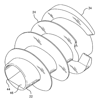
Referring to FIGS. 1 and 2, there is disclosed a hernia tack suitable for
atraumatic
insertion through hernia mesh and into human tissue. Hernia tack 10 generally
includes
CA 02489340 2004-12-10
WO 03/103507 PCT/US03/18739
an elongated barrel portion 12 having a cap or head 14 at a proximal end 16 of
barrel
portion 12. Barrel portion 12 extends distally from head 14 and is preferably
tapered. A
detent may be formed in a proximal surface 15 of head 14 for receipt of
driving
instrumentation. Preferably barrel portion 12 and head cap 14 define a
throughbore 18
therethrough. Throughbore 18 extends from a proximal end 20 of head cap 14 to
a distal
end 22 of barrel portion 12.
Preferably, distal end 22 is smooth or rounded off to avoid traumatizing
tissue and
damaging the mesh as tack 10 is installed. Distal end 22 forms an atraumatic
transition
with the tip of a drive rod to prevent tearing of mesh and tissue during
insertion. Tack 10
can be formed of any biocompatible material and preferably of a material that
is
absorbable. In order to facilitate insertion and retention of hernia tack 10
in tissue, barrel
portion 12 is provided with a tissue thread 24 having a leading edge 26 at a
distal end 28
of tissue thread 24 and a trailing edge 30 at a proximal end 32 of tissue
thread 24. The use
of a tissue thread in a hernia mesh tack allows for a larger surface bearing
area against
tissue to prevent pulling out of tissue. This is a clear advantage over prior
art types of
tacks. Leading edge 26 of tissue thread 24 tapers toward distal end 22 of
barrel portion
12 to facilitate rotating tack 10 through hernia mesh and a tissue puncture
made with a
drive instrument discussed as discussed more fully hereinbelow.
In order to utilize hernia tack 10 with a suitable drive instrument, head 14
is
provided with a drive thread 34. Drive thread 34 has a leading edge 36 at a
distal end 38
of drive thread 34 and a trailing edge 40 at a proximal end 42 of drive thread
34. The
maximum diameter of drive thread 34 is greater than the maximum diameter of
tissue
6
CA 02489340 2004-12-10
WO 03/103507 PCT/US03/18739
thread 24 so that as tack 10 is rotated through a drive instrument tissue
thread 24 does not
contact the drive instrument and thread 24 is not damaged.
Referring to FIGS. 4 and 5, a drive instrument, described hereinbelow, is
configured to pass a drive rod into the detent in head 14 or through
throughbore 18 and
rotate tack 10. As shown, throughbore 18 has an arcuate portion 44 and a flat
portion 46
which combine to form a generally D-shaped throughbore. This allows a
similarly
shaped drive rod to engage inner surface of throughbore 18 and rotate tack 10.
Tissue thread 24 has a proximal surface 48 which is oriented approximately
perpendicularly or at a 90° angle to barrel portion 12. This provides a
generally flat
surface area to engage tissue to avoid pulling out of tack 10 from tissue.
Referring for the
moment to FIG. 7, a distal face 49 of thread 24 forms and obtuse angle with
barrel
portion 12 to facilitate insertion of tack 10.
As shown in FIG. 3, a proximal end of head 14 has a chamfered surface 50 to
facilitate receipt of insertion tools, such as a drive rod, in throughbore 18.
Referring now to FIGS. 6 and 7, drive thread 34 is more clearly illustrated.
As
shown, leading edge 36 and trailing edge 40 of drive thread 34 are rounded so
as to
facilitate ease of insertion in a drive apparatus. Further, trailing edge 40
is flush with a
proximal surface 15 of head 14 to facilitate reengagement of tack 10 by an
insertion
instrument to facilitate removal of tack 10.
Referring to FIG. 7 and 8, it can be seen that trailing edge 30 of tissue
thread 24
and leading edge 36 of drive thread 34 are discontinuous and do not form one
continuous
thread. In particular, a tapered edge 37 of drive thread 34 prevents drive
thread 34 from
7
CA 02489340 2004-12-10
WO 03/103507 PCT/US03/18739
continuing into tissue after trailing edge 30 of tissue thread 24 is fully
inserted in the
tissue. FIG. 8 also shows the D-shaped throughbore 18.
FIG. 9 illustrates the generally flat proximal surface 48 of tissue thread 24
as well
as the transition zone 51 between tissue thread 24 and drive thread 34.
Referring now to FIGS. 10 and 11 there is illustrated an alternative
embodiment
of a hernia tack 52 which in most respects is the same as hernia tack 10.
However, hernia
tack 52 includes a square shaped throughbore 54 for engagement with a
different style
drive apparatus. The square shape of throughbore 54 provides more surface area
for the
insertion tool to engage. This may aid in driving tack 52 into tough tissues
without
possibility of stripping throughbore 54.
Similarly, referring now to FIG. 12, there is illustrated an end view of an
alternative tack 56 which has a polygonal shaped throughbore 58 to provide yet
more
surface area for engagement with insertion instrumentation . Various other
throughbore
shapes, such as, for example, oval, star shaped, etc. may be provided to
operate with
various insertion instruments. Any non-circular shape for the cross section of
the
throughbore is contemplated herein.
Referring now to FIG. 13, there is disclosed an alternative embodiment of a
surgical tack having a differing style tissue thread. Tack 60 generally
includes a barrel
portion 62 and a head 64. Head 64 has a drive thread 65 to engage threads in
an insertion
tool. In this embodiment of tack 60, a proximal surface 68 of a tissue thread
66
generally forms an obtuse angle with respect to barrel portion 62. This angle
of tissue
thread 66 may assist in those situations where tack 60 needs to be removed or
backed out
of the tissue and the mesh. A distal surface 69 of thread 66 may be oriented
substantially
CA 02489340 2004-12-10
WO 03/103507 PCT/US03/18739
perpendicular to barrel portion 62 as shown. While not specifically shown,
either or both
of proximal surface 68 and distal surface 69 of tissue thread 66 may form an
angle of less
than 90 degrees with barrel portion 62 to aid in anchoring tack 60 within
tissue.
Referring now to FIG. 14, there is disclosed a further alternative embodiment
of a
surgical tack. Tack 70 is similar to tacks 10 and 60 hereinabove and generally
includes a
barrel portion 72 having a head 74. Head 74 has a drive thread 75 to engage
the threads
in an insertion instrument. Tissue thread 76 formed on body portion 72
includes a distal
surface 78 which forms an obtuse angle with barrel portion 72. This may assist
in driving
tack 70 through the mesh and into the tissue. As shown, a proximal surface 79
of tissue
thread 76 may be oriented perpendicular to barrel portion 72.
Referring now to FIG. 1 S there is illustrated a drive rod 80 for use in a
tack
applying instrument. Drive rod 84 is utilized in those insertion tools which
are
configured to apply a single tack to hernia mesh and tissue. Drive rod 80
generally
includes a proximal end section 82 configured to be engaged by an actuation
mechanism
of a surgical instrument such that actuation of the instrument rotates drive
rod 80. Drive
rod 80 also includes a center section 84 extending distally from proximal end
section 82
and a distal section 86 extending distally from center section 84. Preferably,
distal
section 86 terminates in a sharp tissue penetrating tip 88.
As best shown in FIGS. 16 and 17, distal section 86 of drive rod 80 includes a
flat
portion 90 and an arcuate portion 92 which forms a generally D-shape so as to
engage the
generally D-shaped throughbore of a tack. As best shown in FIG. 18, an
abutment
surface 94 is formed between a distal end 96 of center section 84 and a
proximal end 98
9
CA 02489340 2004-12-10
WO 03/103507 PCT/US03/18739
of distal section 86. This abutment surface 94 is configured to engage the
proximal
surface of the head of the tack.
Referring now to FIGS. 18-20, and initially with respect to FIG. 18, there is
illustrated drive rod 100 for use with multiple tacks. Drive rod 100 generally
includes a
proximal section 102 and a distal section 104. An abutment surface 106 is
formed
between distal section 104 and proximal section 102 to engage a tack. Distal
section 104
sufficiently elongate so as to receive multiple tacks therealong.
Referring to FIG. 19, distal section 104 includes a flat surface 108 and an
arcuate
surface 110 which is configured to engage the throughbore of the prior
disclosed hernia
tacks. As shown in FIG. 20, distal section 104 has a pointed distal end 112.
Referring to FIG. 21, there is illustrated a pair of hernia tacks 60 provided
on
drive rod 114.
Referring now to FIG. 22, the distal end of an insertion tool is disclosed for
providing multiple surgical tacks 60 to hernia mesh and tissue. Insertion tool
120
includes an outer tube 122 having rotatable drive rod 100 positioned within
outer tube
122. As discussed hereinabove, various known handle mechanisms may be provided
to
rotate drive rod 100 relative to outer tube 122. One known device is disclosed
in U.S.
Patent No. 5,582,616 to Bolduc. Drive rod 100 includes pointed distal end 112
to
facilitate initially piercing tissue and mesh. As shown, insertion tool 120
includes an
inner thread 124 which is configured to engage drive thread 65 of head 64 of a
tack 60.
Inner thread 124 may be integrally formed in outer tube 122. It should be
noted that
inner thread 124 may extend completely or partially along the inner surface of
outer tube
122. If thread 124 is only provided at the distal end of tube 122, a spring
may be used to
CA 02489340 2004-12-10
WO 03/103507 PCT/US03/18739
bias the tacks distally toward thread 124 in tube 122. A distal end 125 of
inner thread
124 is positioned flush with the distal end of tube 122. This facilitates
reengagement
inner thread 124 with thread 65 of head 64 in the event that tack 60 needs to
be
withdrawn after installation. As clearly shown, when tacks 60 are loaded into
insertion
tool 120, tissue thread 66 does not contact inner thread 124 and is not
damaged thereby.
Referring to Fig. 23, in use, insertion tool 120 having a handle 126, elongate
tube
122 extending distally from handle 126, and an actuator 128 configured to
rotate inner
rod 100, is positioned such that pointed distal end 112 is against mesh m and
underlying
tissue t and covering the henual defect d. Thereafter, a handle mechanism (not
shown)
may be actuated to rotate drive rod 100 relative to outer tube 212. This
causes drive
thread 65 of head cap 64 of tack 60 to engage inner thread 124 and drive tack
60 through
the mesh m and into tissue t. As noted above, tacks 60 may be biased distally
by a spring
surrounding drive rod 100 or maybe moved distally by providing inner thread
partially, or
substantially along the entire length of, outer tube 122.
Refernng now to FIG. 24 there is disclosed a display model of the hernia tack
and
an insertion tool which can be used to show how the actual tack, which is very
small on
the order of a few millimeters in diameter, is driven out of the insertion
tool and into
mock tissue and mesh. Display model 130 includes an insertion tool 132 and a
tack 134.
Insertion tool 130 has an outer tube 136 having an inner thread 138. As with
the insertion
tools described hereinabove, thread 138 may be integrally formed in outer tube
136 or a
separate component affixed to an inner surface of outer tube 136.
Additionally, while
thread 138 is contemplated as extending completely through outer tube 136,
thread 138
11
CA 02489340 2004-12-10
WO 03/103507 PCT/US03/18739
may only be provided at the distal end of tube 136 and a spring or other means
(not
shown) may be provided to bias tacks distally within outer tube 136.
Insertion tool 132 also includes a drive knob 140 having a drive rod 142
extending distally therefrom and through inner tube 136. Drive rod 142 has a
pointed
distal end to simulate piercing tissue. Drive rod 142 also has arcuate and
flat sections
configured to engage tack 134 similar to drive rod 100 hereinabove. Tack 134
has a
throughbore 144 to receive drive rod 142.
To demonstrate the use of the tack and applier, tack 134 is placed in tube 136
and
insertion tool 132 is manipulated to position drive rod 142 in a through bore
150 of tack
134. Knob 140 is then rotated to drive tack 134 out of tube 136.
It will be understood that various modifications may be made to the
embodiments
disclosed herein. For example, as discussed above, other configurations for
the
throughbore in the tack, as well as various angles of the tissue threads, may
be provided
on the tacks. Therefore, the above description should not be construed as
limiting, but
merely as exemplifications of preferred embodiments. Those skilled in the art
will
envision other modifications within the scope and spirit of the claims
appended hereto.
12