Note: Descriptions are shown in the official language in which they were submitted.
CA 02489508 2010-03-29
METHOD AND APPARATUS FOR ANASTOMOSIS
BACKGROUND
1. Technical Field
The present disclosure relates to apparatus and methods used for joining
tissue
portions and more particularly, to anastomotic devices and methods for
positioning and
joining two hollow body parts.
2. Background of Related Art
Anastomosis is the bringing together and/or joining of two hollow or tubular
structures. When it is desired to suture a body conduit, typically for
attachment to another
body conduit, sutures are placed around the circumference of the conduit in
order to
maintain the patency of its lumen or channel. It can be appreciated that the
sutures made
on top of the conduit (i.e., on the side facing the surgeon) are made
relatively more easily
than the sutures made underneath the conduit (i.e., on the side facing away
from the
surgeon).
The complexity of joining two body vessels is made manifestly apparent in a
surgical procedure referred to generally as a radical prostatectomy (i.e., a
well established
surgical procedure for patients with localized prostatic carcinoma). In
general, radical
prostatectomy procedures require the removal of cancerous tissue while
preserving sexual
function and continence in the patient. There are two primary types of radical
prostatectomy approaches for the removal of prostate cancer, the retropubic
approach and
the perineal approach.
In the retropubic approach, a long up-and-down incision is made in the midline
of
the abdomen from the navel to the pubic bone. After the lymph nodes have .been
removed
for study by the pathologist and a determination has been made to proceed with
the
1
CA 02489508 2004-12-14
WO 2004/000138 PCT/US2003/019516
removal of the prostate gland, the space underneath the pubic bone is cleaned
and
dissected and the removal of the entire prostate gland is generally begun at
the end that is
farthest from the bladder, i.e., next to the external urethral sphincter.
Next, the prostatic
urethra is divided, the prostatic urethra and the prostate gland through which
it goes are
then pulled upwards toward the bladder while the dissection continues behind
the prostate
gland, separating it from the layer of tissue that is connected to the rectum
on its other
side. As the dissection continues between the prostate and the rectum, the
seminal
vesicles, which are behind the base of the bladder, will be removed along with
the prostate
gland. Once the seminal vesicles are free, the entire prostate gland and the
seminal
vesicles are removed. The bladder neck is then stitched closed to a small
enough diameter
so that it is about the same size as the stump of the urethra from which the
prostate was
detached. The bladder neck is then pulled down into the pelvis and positioned
against the
urethral stump and stitched thereto. This stitching is done typically around a
Foley
catheter which has been inserted through the penis all the way into the
bladder.
In the perineal approach, an inverted "U" shaped incision is made going right
over
the anus, with the center of the "U" about three centimeters above the margin
of the anus.
The prostate gland is then freed from its surrounding structures by gentle
dissection, and
the urethra at the end of the prostate farthest from the bladder is isolated
and divided. The
bladder neck is freed from the prostate, and, once the prostate gland has been
removed and
the bladder neck has been closed sufficiently so that the size of its opening
approximates
the size of the urethral opening, the urethra and the bladder neck are
stitched together.
Once again, a Foley catheter is left in place postoperatively for about two
weeks.
In each of the above described procedures, it is the attachment of the
urethral
stump to the bladder neck which is particularly difficult and complex. This
difficulty is
complicated by the tendency of the urethral stump to retract into adjacent
tissue. As a
result, considerable time and effort must be expended to re-expose the
urethral stump and
begin the re-anastomosis procedure. Further complicating this procedure is the
fact that
the urethral stump is hidden beneath the pubic bone thus requiring that the
surgeon work at
a difficult angle and in positions that are uncomfortable and limiting.
Various devices have been proposed for facilitating this procedure. In U.S.
Pat.
No. 5,591,179, issued to Edelstein, there is disclosed a suturing device
including a shaft
with portions defining an interior channel extending between a proximal and a
distal end
of the shaft. This channel includes a generally axial lumen which extends to
the proximal
end of the shaft and a generally transverse lumen which extends from the axial
lumen
2
CA 02489508 2004-12-14
WO 2004/000138 PCT/US2003/019516
distally outwardly to an exit hole at the outer surface of the shaft. A needle
and suture can
be back loaded into the transverse lumen of the channel while a generally non-
compressible member can be movably mounted in the axial lumen of the channel.
At the
proximal end of the shaft a handle is provided with means operative to push
the member
distally through the lumen to deploy or expel the needle.
In U.S. Pat. No. 4,911,164, issued to Roth, there is disclosed a suture guide
with a
curved distal portion. The distal portion of the suture guide has a plurality
of exterior axial
grooves which can be used to align and guide a curved needle and attached
suture. In
order to drive the urethral stump to an accessible position, the device is
provided with a
, plurality of outwardly extendable members which engage the lumen of the
urethra. These
members make it possible to push the urethral stump into approximation with
the bladder
neck.
In U.S. Pat. No. 5,047,039, issued to Avant et al., there is disclosed a
surgical
device for the ligation of a dorsal vein and subsequent anastomosis. This
device contains
a pair of enclosed needles each having an attached suture which needles may be
driven
from the shaft of the device into adjacent tissue.
In general, none of the devices disclosed in the prior art references above is
simple
to use or makes the anastomosis of the urethral stump to the bladder neck
easier. As such,
each surgical procedure using prior art devices continues to be time consuming
and
requires great skill in order to be performed. Accordingly, the need exists
for anastomosis
devices which overcome the drawbacks of the prior art devices and which are
quick and
simple to use.
SUMMARY
Apparatus and methods for performing a surgical anastomotic procedure are
disclosed herein. According to one aspect of the present disclosure, an
apparatus for
approximating body vessels includes at least one fastener. Each fastener
includes a first
fastener portion having an anchoring leg portion, and a second fastener port
ion having an
anchoring leg portion, wherein the first and second fastener portions are
operatively
associated with one another for selectively fixing the position of the first
fastener portion
and the second fastener portion with respect to one another. The apparatus
further
includes a first member configured and adapted to engage the first fastener
portion, and a
second member configured and adapted to engage the second fastener portion,
the first
3
CA 02489508 2004-12-14
WO 2004/000138 PCT/US2003/019516
member and the second member being movable with respect to one another to move
the
first fastener portion and second fastener portion with respect to one
another.
It is envisioned that each first fastener portion and second fastener portion
has a
locking leg portion and a first position in which the anchoring leg portion is
adjacent the
locking leg portion and a second position in which the anchoring leg portion
is spaced a
distance from the locking leg portion.
Each of the anchoring leg portions of the first and second fastener portions
can
include a sharpened tip, wherein the sharpened tips are oriented substantially
toward one
another. Each anchoring leg portion can be integrally connected to the
respective locking
leg portion.
In certain embodiments, the apparatus further includes an insertion sleeve.
Accordingly, it is envisioned that each anchoring leg portion can be biased to
a position
spaced from the respective locking leg portion and collapsible to a position
in close
proximity to the respective locking leg portion.
It is envisioned that each fastener can be made from stainless steel,
titanium,
polyglycolic acid and polylactic acid.
In certain embodiments, the first fastener portion and the second fastener
portion
include inter-engaging fixing elements. The fixing elements can include a
series of
projections formed along a surface of the first fastener portion, and a
locking passage
formed along a surface of the second fastener portion, the locking passage
being
configured and dimensioned to receive an end of the first fastener portion
therein. The
locking passage can include at least one projection extending from an inner
surface thereof
and the at least one projection is configured and dimensioned to engage the
series of
projections formed along the surface of the first fastener portion. Desirably,
the fixing
elements are saw toothed. Accordingly, the fixing elements permit movement of
the first
fastener portion relative to the second fastener portion in a first direction,
while preventing
movement in a second direction.
It is envisioned that each of the first fastener portion and the second
fastener
portion can have a locking leg portion pivotably connected to the respective
anchoring leg
portion.
Each anchoring leg portion can include a suture secured thereto.
In certain embodiments, the apparatus can further include an insertion sleeve.
It is
envisioned that a plurality of fasteners can be radially disposed about the
lumen of the
insertion sleeve.
4
CA 02489508 2004-12-14
WO 2004/000138 PCT/US2003/019516
It is envisioned that each first fastener portion can include a lip extending
from the
first fastener portion and the first member can include an anvil having a hook
formed at a
distal end thereof for engaging the lip of the first fastener portion. It is
further envisioned
that each second fastener portion can include a lip extending from the second
fastener
portion and the second member can include a pusher having a recess formed in a
distal end
thereof for engaging the lip of the second fastener portion.
In certain embodiments, the apparatus can further include fixing elements on
each
of the first and second fastener portions. The fixing elements can include a
series of
projections formed along a surface of the first fastener portion, and a
locking passage
formed along a surface of the second fastener portion, the locking passage
being
configured and dimensioned to receive an end of the locking leg portion of the
first
fastener portion therein. The locking passage includes at least one projection
extending
from an inner surface thereof which at least one projection is configured and
dimensioned
to engage the series of projections formed along the surface of the first
fastener portion.
The locking passage is defined by a pair of side walls extending from the
locking leg
portion of the second fastener portion and an end wall interconnecting and
extending
between the pair of side walls, the at least one projection of the locking
passage being
formed on an inner surface of the end wall.
According to another aspect of the present disclosure, a method of
approximating a
first body vessel and a second body vessel is provided. The method includes
the step of
providing an apparatus for approximating the first body vessel and the second
body vessel.
The apparatus includes at least one fastener having a first fastener portion
having an
anchoring leg portion, and a second fastener portion having an anchoring leg
portion,
wherein the first and second fastener portions are operatively associated with
one another
for selectively fixing the position of the first fastener portion and the
second fastener
portion with respect to one another, a first member configured and adapted to
engage the
first fastener portion, and a second member configured and adapted to engage
the second
fastener portion, the first member and the second member being movable with
respect to
one another to move the first fastener portion and second fastener portion
with respect to
one another.
The method further includes the steps of passing the apparatus through the
first
body vessel and through an opening in the second body vessel such that the
anchoring leg
portion of the first fastener portion is positioned within the second body
vessel,
withdrawing the first member to drive the anchoring leg portion of the first
fastener
5
CA 02489508 2004-12-14
WO 2004/000138 PCT/US2003/019516
portion into the wall of second body vessel, advancing the second member to
drive the
anchoring leg portion of the second fastener portion into the wall of the
first body vessel,
and approximating the first member and the second member to approximate the
anchoring
leg portions of the first and second fastener portions with one another and to
approximate
the first and second body vessels with one another, wherein the fixing
elements engage
one another and inhibit separation of the first and second body vessels from
one another.
It is envisioned that the anchoring leg portions can be biased to an expanded
position and the fastener can be disposed within an insertion sleeve so as to
maintain the
fastener in a collapsed position. The method can further include the step of
withdrawing
the insertion sleeve so as to allow the anchoring leg portion to expand.
These and other features of the apparatus disclosed herein, will become
apparent
through reference to the following description of embodiments, the
accompanying
drawings and the claims.
BRIEF DESCRIPTION OF THE DRAWINGS
The accompanying drawings, which are incorporated in and constitute a part of
this
specification, illustrate embodiments of the disclosure and together with the
detailed
description of the embodiments given below, serve to explain the principles of
the present
disclosure.
FIG. 1 is a top plan view of a fastener, in accordance with an embodiment of
the
present disclosure, shown in a separated condition;
FIG. 2 is a side elevational view of the fastener of FIG. 1;
FIG. 3 is a top plan view the fastener of FIGS. 1-2, shown in a coupled
condition;
FIG. 4 is a side elevational view of the fastener of FIGS. 1-3;
FIG. 5 is an enlarged cross-sectional view of the indicated area of FIG. 3;
FIG. 6 is an enlarged end view of the fastener of FIGS. 1-5;
FIG. 7 is a cross-sectional side elevational view illustrating the positioning
of the
insertion tool and fastener into a hollow body organ;
FIG. 8 is a cross-sectional side elevational view illustrating the positioning
of the
insertion tool and the fastener as well as the expansion of the distal of the
fastener in the
hollow body organ in order to anchor the distal end of the fastener in the
walls of the
hollow body organ;
6
CA 02489508 2010-03-29
FIG. 9 is a cross-sectional side elevational view illustrating the expansion
of the
proximal end of the fastener in order to anchor the proximal end of the
fastener to the
walls of the body lumen;
FIG. 10 is a cross-sectional side elevational view illustrating the
approximation of
the hollow body organ to the body lumen;
FIG. 11 is a cross-sectional side elevational view illustrating the retraction
of the
insertion tool;
FIG. 12 is a cross-sectional side elevational view illustrating the final
anastomosed
hollow body organ and body lumen with the fastener anchored in position;
FIG. 13A is a side elevational view of a proximal leg of a fastener in
accordance
with an alternative embodiment of the present disclosure; and
FIG. 13B is a side elevational view of a distal leg of a fastener in
accordance with
the alternative embodiment of the present disclosure.
DETAILED DESCRIPTION OF PREFERRED EMBODIMENTS
Preferred embodiments of the presently disclosed anastomosis apparatus will
now
be described in detail with reference to the drawing figures wherein like
reference
numerals identify similar or identical elements. In the drawings and in the
description
which follows, the term "proximal", as is traditional, will refer to the end
of the surgical
device or instrument of the present disclosure which is closest to the
operator, while the
term "distal" will refer to the end of the device or instrument which is
furthest from the
operator.
An anastomosis apparatus, in accordance with an embodiment of the present
disclosure, is shown in FIGS. 1-12. Although the anastornosis apparatus offers
significant
advantages to a radical prostatectomy procedure, it will be understood that
the device is
applicable for use in any anastomotic procedure where two body vessels are to
be brought
together and joined.
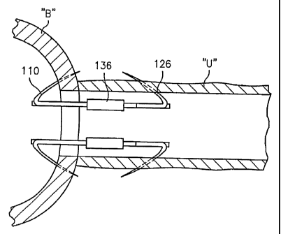
As seen in FIGS. 1-6, the anastomosis apparatus includes at least one fastener
102
and preferably a plurality of fasteners 102 radially disposed about a lumen
184 of an
insertion sleeve 180 (see FIG. 7). Each fastener 102 includes a first fastener
portion 104
and a second fastener portion 106. First fastener portion 104 of fastener 102
includes a
locking leg portion 108 and an anchoring leg portion 110 integrally formed
with locking
leg portion 108. In particular, locking leg portion 108 includes a proximal
end 112 and a
distal end 114 from which anchoring leg portion 110 extends. Anchoring leg
portion 110
7
CA 02489508 2004-12-14
WO 2004/000138 PCT/US2003/019516
includes a distal end 116 integrally coupled to distal end 114 of locking leg
portion 108
and a sharpened proximal tip 118. Desirably, sharpened proximal tip 118 of
anchoring leg
portion 110 is oriented towards proximal end 112 of locking leg portion 108.
Anchoring
leg portion 110 has a first position "A" in which sharpened proximal tip 118
is spaced a
distance from locking leg portion 108 and can be collapsed to a second
position "C" (as
seen in phantom in FIGS. 2 and 3) in which sharpened proximal tip 118 is in
close
proximity to locking leg portion 108.
Preferably, locking leg portion 108 of first fastener portion 104 includes
fixing
elements for engaging second fastener portion 106. The fixing elements in
certain
embodiments comprise a series of projections 120 formed along a side thereof
and
extending from proximal end 112 toward distal end 114. First fastener portion
104 of
fastener 102 further preferably includes a lip 122 projecting distally from
distal end 110 of
locking leg portion 108.
Second fastener portion 106 of fasteners 102 includes a locking leg portion
124
and an anchoring leg portion 126 integrally formed with locking leg portion
124. In
particular, locking leg portion 124 includes a distal end 128 and a proximal
end 130 from
which anchoring leg portion 126 extends. Anchoring leg portion 126 includes a
proximal
end 132 integrally coupled to proximal end 130 of locking leg portion 124 and
a sharpened
distal tip 134. Desirably, sharpened distal tip 134 of anchoring leg portion
126 is oriented
towards distal end 128 of locking leg portion 124. Anchoring leg portion 126
has a first
position "A" in which sharpened distal tip 134 is spaced a distance from
distal end 128 of
locking leg portion 124 and can be collapsed to a second position "C" (as seen
in phantom
in FIGS. 2 and 4) in which sharpened distal tip 134 is in close proximity to
locking leg
portion 124.
Preferably, locking leg portion 124 of second fastener portion 106 includes a
locking passage 136 formed along a side surface thereof. As seen in FIG. 6,
locking
passage 136 is defined by an upper wall 138 extending from an upper surface of
locking
leg portion 124, a lower wall 140 extending from a lower surface of locking
leg portion
124 and an interconnecting side wall 142 extending between the terminal ends
of upper
wall 138 and lower wall 140. Locking passage 136 includes at least one, and
desirably a
plurality of fixing elements for engaging the fixing elements of the first
fastener portion
104. The locking passage 136 shown has fixing elements in the form of a
plurality of
projections 144 formed along an inner surface of interconnecting side wall 142
and
oriented toward locking leg portion 124. Locking passage 136 is sized and
dimensioned to
8
CA 02489508 2004-12-14
WO 2004/000138 PCT/US2003/019516
slidably receive an end of first fastener portion 104 therethrough. In
particular, when
locking leg portion 108 of first fastener portion 104 is inserted into locking
passage 136 of
second fastener portion 106, projections 120 of locking leg portion 108 engage
projections
144 of locking passage 136 to thereby effectively lock first fastener portion
104 of fastener
102 in position with respect to second fastener portion 106 of fastener 102.
Similar to first fastener portion 104 of fastener 102, second fastener portion
106 of
fastener 102 includes a lip 148 projecting proximally from proximal end 130 of
locking
leg portion 124.
As seen in FIG. 5, it is contemplated that projections 120 of locking leg
portion
108 and projections 144 of side wall 142 of locking passage 136 are teeth-like
(e.g., saw
toothed) projections 146a, 146b, respectively, configured and adapted to
permit locking
leg portion 108 to be inserted into locking passage 136 and hindering
withdrawal of
locking leg portion 108 therefrom. In particular, projections 146a, 146b are
configured
and adapted to permit'locking leg portion 108 to slide in direction "D" while
locking
passage 136 is permitted to slide in direction "E". However, once projections
146a and
projections 146b engage one another, projections 146a, 146b prevent locking
leg portion
108 from sliding in a direction opposite to direction "D" and prevent locking
passage 136
from sliding in the direction opposite from "E". In other words, projections
146a, 146b
are configured and adapted to allow uni-directional movement of locking leg
portion 108
relative to locking passage 136 and in turn uni-directional movement of first
fastener
portion 104 relative to second fastener portion 106.
While projections 120 of locking leg portion 108 and locking passage 136 are
shown and described as being formed along a side surface of first fastener
portion 104 and
second fastener portion 106, respectively, it is envisioned and within the
scope of the
present disclosure that projections 120 can be provided along any surface of
locking leg
portion 108 of first fastener portion 104 and locking passage 136 can be
provided along
any surface of locking leg portion 124 of second fastener portion 106.
First fastener portion 104 and second fastener portion 106 of fastener 102 can
be
made from any surgical grade material, such as stainless steel or titanium. It
is envisioned
that first and second fastener portions 104, 106 are preferably made from a
medical grade
bio-absorbable material, such as, for example, polyglycolic acid (PGA) and/or
polylactic
acid (PLA). Preferably, the material and dimensions of fasteners 102 are
selected such
that fasteners 102 will dissolve after a predetermined period of time while
retaining their
9
CA 02489508 2010-03-29
structural integrity for a period of time sufficient to assure proper healing
of the
anastomosis site.
As seen in phantom in FIG. 7, the anastomosis apparatus includes a first
member
or anvil 150, a second member or pusher 170, and a shaft 190 for mounting the
fasteners
102 in an insertion sleeve 180. The anvil 150 and pusher 170 are shown in
phantom in
FIGS. 3 and 4. Anvil 150 includes an elongate body portion 152 and a hook 154
formed
at a distal end 156 thereof. Hook 154 of anvil 150 is configured and adapted
to engage lip
120 of first fastener portion 104 of fastener 102. Pusher 170 includes an
elongate body
portion 172 and a recess 174 formed at a distal end 176 thereof. Recess 174 of
pusher 170
is configured and adapted to engage lip 146 of second fastener portion 106 of
fastener 102.
As seen in FIGS. 7-11, insertion sleeve 180 includes a distal end 182, a
proximal
end (not shown) and defines a lumen 184 extending therethrough which defines a
central
axis. Shaft 190 is configured and adapted to be slidably received in lumen 184
of insertion
sleeve 180. It is envisioned that shaft 190 include a plurality of radially
oriented
longitudinally extending grooves (not shown) formed therein. Accordingly, each
groove
of shaft 190 can be configured and adapted to receive a respective anvil 150,
pusher 170
and fastener. 102. Preferably, shaft 190 is sized such that when shaft 190 is
inserted into
sleeve 180, anchoring leg portion 108 of first fastener portion 104 and
anchoring leg
portion 124 of second fastener portion 106 are in the second position "C" (see
FIG. 7).
Anvil 150 and pusher 170 are arranged with respect to one another so as to
form a
recess for receiving fastener 102 between hook 154 and recess 174. Fastener
102 is
disposed in the recess so that first fastener portion 104 and second fastener
portion 106 are
engaged with one another, leaving room for advancing the anchoring leg
portions toward
one another. A plurality of fasteners 102 are disposed in insertion sleeve
180, with the
shaft 190 disposed between the fasteners 102 and their corresponding anvil and
pusher.
(see FIG. 7).
A preferred method of use and operation of the anastomosis apparatus in
performing a radical prostatectomy anastomosis will now be described in
greater detail
with reference to FIGS. 1-12 and in particular with reference to FIGS. 7-12.
The
anastomosis apparatus can be used in either the retropubic or the perineal
prostatectomy
approaches, or any approach in which the bladder and urethra must be
approximated.
With the prostate removed, the bladder neck "N" of the bladder "B" is first
reconstructed
by everting the inner mucosal lining of bladder "B" and suturing it down to
the outer wall
of bladder "B", using known surgical techniques. Likewise, urethral stump "S"
of urethra
CA 02489508 2010-03-29
"U" is reconstructed by everting the inner mucosal lining of urethral stump
"S" and
suturing it down to the outer wall of urethra "U", using known surgical
techniques.
Preferably, with bladder neck "N" reconstructed, bladder neck "N" is sized to
properly accommodate and retain distal end 180 of sleeve 180 within bladder
"B" using a
standard tennis racket type closure (i.e., the opening of the bladder neck
constituting the
head of the tennis racket and a radial incision extending from the bladder
neck constituting
the handle portion of the tennis racket). The size of the bladder neck will
vary depending
on the patient. Typically, the bladder neck "N" is sized to be approximately 7-
8 mm in
diameter.
With bladder neck "N" reconstructed, the apparatus is passed trans-urethrally
through urethra "U" until distal end 182 of insertion sleeve 180 extends out
of urethral
stump "S" and into bladder "B" through bladder neck "N", as seen in FIG. 7.
With the apparatus so positioned, insertion sleeve 180 is withdrawn in a
proximal
direction to expose sharpened proximal tips 118 of first fastener portions
104. The
anchoring leg portions 110 are biased to the first position "A" so that when
sharpened
proximal tips 118 are exposed from within insertion sleeve 180, anchoring leg
portions
110 of first fastener portions 104 are deployed to the first position "A".
(see FIG. 8).
With anchoring leg portions 110 deployed, hooks 154 of anvils 150 are
withdrawn in a
proximal direction to engage lips 122 of first fastener portions 104 and to
drive sharpened
proximal tips 118 through the wall of bladder "B", see FIG. 9.
As seen in FIG. 9, insertion sleeve 180 is further withdrawn in a proximal
direction
until sharpened distal tips 134 and anchoring leg portion 126 of second
fastener portion
106 are exposed. The anchoring leg portions 126 are biased to the first
position "A" so
that when anchoring leg portions 126 are completely exposed from within
insertion sleeve
180, anchoring leg portions 126 of second fastener portions 106 are deployed
to first
position "A". (see FIG. 9). With anchoring leg portions 126 deployed, pushers
170 are
advanced in a distal direction to engage lips 148 and to drive sharpened
distal tips 134
through the wall of urethral stump "S".
With sharpened proximal tips 118 of first fastener portions 104 penetrating
the
wall of bladder "B" and with sharpened distal tips 134 penetrating the wall of
urethral
stump "S", hooks 154 of anvils 150 are approximated toward recesses 174 of
pushers 170
to thereby approximate anchoring leg portions 110 of first fastener portion
104 and
anchoring leg portions 126 of second fastener portion 106 towards one another.
Concomitantly, as anchor leg portions 110 and 126 are approximated towards one
another
11
CA 02489508 2004-12-14
WO 2004/000138 PCT/US2003/019516
bladder neck "N" is approximated towards urethral stump "S". (see FIG. 10). In
accordance with the present disclosure, approximation of anchor legs 110 and
126 towards
one another results in projections 120 and 144 incrementally engaging one
another and
maintaining the position of anchor leg 110 relative to anchor leg 126.
Accordingly,
projections 120 and 144 prevent bladder "B" from separating from urethra "U".
After bladder neck "N" has been approximated toward urethral stump "S",
pushers
170 and shaft 190 are withdrawn from insertion sleeve 180 and anvils 150
unhooked from
lips 122. (see FIG. 11). Thereafter, anvils 150 and insertion sleeve 180 are
withdrawn
from urethra "U".
An alternate embodiment of a fastener 200, in accordance with the present
disclosure, is shown in FIGS. 13A and 13B. Unlike fastener 102 from above,
fastener 200
includes a first fastener portion 202 and a second fastener portion 204. First
fastener
portion 202 includes a locking leg portion 206 and an anchoring leg portion
208 pivotally
coupled to a proximal end of locking leg portion 206. In the embodiment shown,
anchoring leg portion 208 is pivotally coupled to locking leg portion 206 by a
pivot pin
210, but other means known in the art may also be used. Alternatively, locking
leg portion
206 or anchoring leg portion 208 can be provided with an integrally formed pin
that
extends outwardly for receipt in an aperture formed in the other of
locking'leg portion 206
or anchoring leg portion 208. First fastener portion 202 includes a suture 212
connected to
anchoring leg portion 208 for pulling on anchoring leg portion 208 and lifting
a distal end
of anchoring leg portion 208 away from locking leg portion 206 (e.g., from
first position
"A" to second position "C"). It is contemplated that the proximal end of
locking leg
portion 206 includes a stop (not shown) for stopping the lifting of anchoring
leg portion
208 beyond a predetermined amount.
As seen in FIG. 13B, second fastener portion 204 includes a locking leg
portion
214 and an anchoring leg portion 216 pivotally coupled to a distal end of
locking leg
portion 214 by a pivot pin 218. Alternatively, locking leg portion 214-or
anchoring leg
portion 216 can be provided with an integrally formed pin and extending
outwardly for
receipt in an aperture formed in the other of locking leg portion 214 or
anchoring leg
portion 216. Second fastener portion 204 further includes a suture 220
connected to
anchoring leg portion 216, extending around the distal end of locking leg
portion 214, for
pulling on anchoring leg portion 216 and lifting a proximal end of anchoring
leg portion
216 away from locking leg portion 214 (e.g., from first position "A" to second
position
"C"). It is contemplated that the distal end of locking leg portion 214
includes a stop (not
12
CA 02489508 2004-12-14
WO 2004/000138 PCT/US2003/019516
shown) for stopping the lifting of anchoring leg portion 216 beyond a
predetermined
amount.
While apparatus in accordance with the present disclosure have been described
as
being used in connection with a radical prostatectomy procedure, it is
envisioned that
apparatus having similar structures and modes of operation can be used in
various other
surgical procedures. It will be understood that various modifications may be
made to the
embodiments of the presently disclosed anastomosis device and method disclosed
herein.
For example, one or more fasteners may be arranged in.the insertion sleeve. In
further
embodiments, the insertion sleeve is sized to accommodate the fastener without
requiring
the anchoring leg portions to collapse to position "C". The fastener may
comprise a single
part with a corrugated, hinged or collapsible portion. The fasteners, in
certain
embodiments, comprise a fixing element comprising a separate part.
Therefore, the above description should not be construed as limiting, but
merely as
an exemplification of a preferred embodiment. Those skilled in the art will
envision other
modifications within the scope of the present disclosure.
13