Note: Descriptions are shown in the official language in which they were submitted.
CA 02489646 2004-12-16
WO 02/103710 PCT/US02/19272
WAVELENGTH DISPERSIVE XRF SYSTEM USING
FOCUSING OPTIC FOR EXCITATION AND A FOCUSING
MONOCHROMATOR FOR COLLECTION
Cross-Reference to Related Patents/Applications
[0001] This application contains subject matter which relates to the subject
matter
of the following commouy-owned patents and applications, each of which is
hereby
incorporated herein by reference in its entirety:
[0002] "Use Of A Kumalchov Lens For X-Ray Lithography", by Muradin
A. Kumalchov, U.S. Letters Patent No. 5,175,755, issued December 29, 1992;
[0003] "Device For Controlling Beams Of Particles, X-Ray and Gamma
Quanta", by Muradin A. Kumalchov, U.S. Letters Patent No. 5,192,869, issued
March 9, 1993;
[0004] "Use Of A Kumakhov Lens In Analytic Instruments", by Muradin
A. Kumakhov, U.S. Letters Patent No. 5,497,008, issued March 5, 1996;
[0005] "High Intensity, Small Diameter X-Ray Beam, Capillary Optic
System", by David M. Gibson, U.S. Letters Patent No. 5,570,408, issued
October 29, 1996;
[0006] "Multiple-Channel, Total-Reflection Optic With Controllable
Divergence", by Gibson et al., U.S. Letters Patent No. 5,604,353, issued
February 18, 1997;
[0007] "Multiple Channel Optic", by Qi-Fan Xiao, U.S. Letters Patent No.
5,745,547, issued April 28, 1998;
[0008] "Curved Optical Device and Method Of Fabrication", by Zewu
Chen, U.S. Letters Patent No. 6,285,506 , issued September 4, 2001;
-1-
CA 02489646 2004-12-16
WO 02/103710 PCT/US02/19272
[0009] "Doubly Curved Optical Device With Graded Atomic Planes", by
Zewu Chen, U.S. Letters Patent No. 6,317,483, issued November 13, 2001;
[0010] "Total-Reflection X-Ray Fluorescence Apparatus and Method Using
a Doubly-Curved Optic", by Zewu Chen, U.S. Serial No. 09/667,966, filed
September 22, 2000; and
[0011] "X-Ray Tube and Method and Apparatus for Analyzing Fluid
Streams Using X-Rays", by Radley et al., U.S. Serial No. 60/336,584, filed
December 4, 2001.
Field of the Invention
[0012] The field of the present invention relates to x-ray fluorescence (XRF)
spectroscopy systems, and in particular, to a system and method which include
focusing x-ray optical elements for forming a focusing excitation beam on
samples
and monochromators for collecting secondary x-rays from the sample.
Bacl~~round of the Invention
[0013] X-ray fluorescence (XRF) spectroscopy is widely recognized as a very
accurate method of determining the atomic composition of a material, achieved
by
irradiating a sample with x-rays and observing the resulting secondary x-rays
emitted
by the sample.
[0014] In general, XRF systems consist of a source of excitation radiation (an
x-
ray tube or a radioisotope), a means to detect secondary x-rays from the
sample and
determine their energy or wavelength, and a display of the spectral output.
The
intensity of the secondary x-rays at certain energies or wavelengths is
correlated to the
elemental concentration in the sample. Computer software is often used to
analyze the
data and determine the concentration.
-2-
CA 02489646 2004-12-16
WO 02/103710 PCT/US02/19272
[0015] The process begins by irradiating the sample using a source of x-rays.
As
x-ray photons strike the sample, they knock electrons out of the inner shell
of the
atoms that make up the sample, creating vacancies that destabilize the atoms.
The
atoms stabilize when electrons from the outer shell are transferred to the
inner shells,
and in the process give off characteristic x-ray photons whose energy is the
difference
between the two binding energies of the corresponding shells. There are two
conventional approaches to determining the x-ray spectrum emitted from the
sample.
The first approach is energy dispersive spectrometry (EDS), and the second is
wavelength dispersive spectrometry (WDS). In an energy dispersive spectrometry
system, an energy dispersive detector, such as a solid-state detector or a
proportional
counter, is used to determine the energy spectrum of the emitted photons from
the
sample. In a wavelength spectrometry system, a crystal or a mufti-layer
structure is
used to select a specific x-ray wavelength from the x-rays photons emitted
from the
sample.
[0016] X-ray fluorescence using EDS is the most widely used method of
elemental
concentration analysis. This method has some advantages. First, the EDS
detector can
detect almost all of the elements in the periodic table at once. Second, the
system is
compact because an additional optic is not required on the collection side
compared to
wavelength dispersive x-ray fluorescent systems. Third, a low-power x-ray tube
may
be used because the EDS detector has a large collection solid angle and high
efficiency. There are disadvantages to XRF/EDS systems, however, including
relatively poor sensitivity and poor energy resolution. Also, because the EDS
detector
sees all of the x-rays from the sample, the detector is easily saturated by
the
fluorescent signal from the major elements and the strong scattering of the
primary
beam.
[0017] X-ray fluorescence using WDS has several advantages also, including
higher energy resolution and higher signal-to-background ratio compared with
XRF/EDS systems. Thus, the XRF/WDS approach is a powerful tool for trace
-3-
CA 02489646 2004-12-16
...
0444.042y~0
.>_
P ,fir ; ~. l~ = f ~ ~ ~ ~ -~""~'~~ ~'~ ~.~~'~~.~ ~J~!4'
x ~~.~~~ ~~.v...~ ~ ~w ip ~'
'y~.a'r~ ~~adx~ ~?~.~.~ t7 ~ d ~'~a"J ~H u.
element an~ysis ~d a
Pplications ti?at require high en
~'e disadvan~ ergY re
high ges to conventional
solution, How
Power x"ray cube ~~s systetns~ includin
ever, there
due to 1 g a requiZ.ement
imitations of the t~s a for a
efi'xciency~ ~d a small collecti P r
conventional an
on solid gle P °ach that rest
side o~ ~S system is that the crysta ' ~o~er disadvan~ge o f ~ a 1°t~'
a
Y selects a 1 or.rnulti-layer st~c~e
specific
x-ray wavele °n tire collection
c~'s~ system is needed for zn~.ti_
n~ and a sc
g mech~sm or ~~ti_
detector saturation may be avo,
element detection, This
Therefore, ~
zded, but ~t results ~ a com
h~ the advan~ge that
compared to..~ S systems ~.e typically b Plicated alignme
ADS systems. ~kY~ complex and more ex nt. .
I8j LISP Pensive as
5~~82,847 to
memg o~y polychromatic optiNelson discloses ~ energy di
ration is made of di~.actin s zn both the detection and col ecsive (E'DS )
systenx,
g optics in either the excitation or tzon paths. No
f 0018 .1 ] W~02/25258 to
colIectio
system. Even x Ray pptical S Inc n Paths.
~ou~ monoc
Ystems~ s also s~.ictI
limited to s wavele ~oma~c excitation is used _ Y an EDS
Peeifxc ngths with a detec '
the detection
disclosed or taught by t~s doc
tzon optic -. the
pad is not
broader bid o(wavelengths
re is no detection optic
utnent. Therefore, the dete
EDS tech~ques. ~d processes this broader b coon system encounters a
and using conventional
(ooI8.21 EP 0339713 to N .V
discussed ab - Philips discloses a
ove, this doc ~S system
very large s~ple are dent discloses the c°nve n~ t ~ however ~
'~ a Puihole/slit 6 ti
ratio ech~que of ilIuznina
s severely I~~g the collection
to define the angle
n
ga
_ ofutc'
_ I
sugges'tio solid deuce a
advantages o f a f oc~ing optic; provide " ogle' There is no disclosur pon
optic 22'
the prese g a small s . e> teac
invention is "placed~a rat invention. The sm~l s ~ple spot size, ~dy~ a~~g or
. _
ndant
~pIe spot size ofthe present
at position 6~ but without limidn
~e detection g the
optic.
. collection solid
foa1s.31 the "
ogle of
n~ et al, Microprobe x
Focusing Di~,actors,"~ '~y Fluorescence
PpI. Phys Lei. 7I (I 3) I gg4-I S ~~ ~e Use of point..
$6, Sept. I997 is similar to
,.4 ,
I~:~ItIpI~CI ~~'~~'.
~. _.....:~,_;
a .
0444.042W0 '~~ ~'P ~' E ~ ~'~' ~":~~ ~' ~'d
..._....::~ ~,:.~ ~,
..s
CA 02489646 2004-12-16
W002/25258, discussed above. Even though monochromatic excitation is used -
the
detection path is not limited to specific wavelengths with a detection optic -
there is
no detection optic disclosed or taught by this document.
[0018.4] USP 5,406,609 to Arai et al. is also similar to W002/25258 -
monochromatic excitation with a standard EDS detection scheme.
[ 0018 . 5 ] While most XRF instruments are generally for the analysis of a
wide range
of elements, there are many important applications in industry process control
that
require single element or limited element detection. Thus, the present
invention is
directed to providing compact XRFlWDS systems that provide an ultra high
sensitivity or high speed analysis for a limited number of elements.
Sumuiary of the Invention
[0019] The shortcomings of the prior approaches are overcome, and additional
advantages are provided, by the present invention which in one aspect
comprises an x-
ray fluorescence (~RF) spectroscopy system. The XRF system includes at least
one
source of x-ray radiation and at least one excitation optic disposed between
the at least
i
one x-ray radiation source and the sample. The at least one excitation optic
collects x-
ray radiation from the at least one source and focuses the x-ray radiation to
a focal point
on the sample to incite at least one analyte in the sample to fluoresce. T'he
system further includes at least one x-ray detector and at least one
collection optic. The
at least one collection optic comprises at least one doubly curved dif&acting
optic
disposed between the sample and the at least one x-ray detector for collecting
x-ray
- 4.1 -
"I~ll~II~~IDI~[C~ ~HEE'
CA 02489646 2004-12-16
WO 02/103710 PCT/US02/19272
fluorescence from the focal point on the sample and directing the fluorescent
x-rays
towards the at least one x-ray detector.
[0020] Numerous enhancements on the above-described XRF spectroscopy system
are also described and claimed herein. For example, the at least one source of
x-ray
radiation could comprise at least one electron bombardment x-ray source. The
at least
one excitation optic could comprise at least one focusing polychromatic optic,
for
example, one or more polycapillary optics, and/or could comprise at least one
focusing
monochromatic optic. The focusing monochromatic optics) could comprise at
least
one doubly curved crystal and/or at least one doubly curved mufti-layer optic.
The
focal point could have a focal spot size of less than 500 microns, and the
sample could
be a solid or a fluid. Further the sample could be a petroleum based product,
such as
gasoline, diesel, crude oil or lubrication oil. The at least one analyte to be
incited
within the sample could comprise sulfur and/or iron. In addition, the x-ray
radiation
focused on the sample may be incident on the sample at an angle less than the
angle of
total external reflection, as desirable for total reflection x-ray
fluorescence (TXRF), or
the x-ray radiation focused on the sample may be incident on the sample at an
angle
greater than the angle of total external reflection, as desirable for normal x-
ray
fluorescence.
[0021] Further enhancements may include the at least one collection optic
directing x-rays of the at least one analyte towards the detectors) for
determining
concentration of the at least one analyte in the sample or a thickness of the
sample.
Further, the at least one doubly curved diffracting optic of the at least one
collection
optic could comprise at least one doubly curved crystal. The at least one
doubly
curved crystal could have a Johann geometry, a Johannson geometry, a partial
Johannson geometry approximation, or could comprise a logarithmic spiral
crystal
optic. Still further, the at least one doubly curved diffracting optic could
comprise at
least one doubly curved mufti-layer optic, which could be a doubly curved
graded
optic, or a doubly curved logarithmic spiral optic in certain embodiments.
Still
-5-
CA 02489646 2004-12-16
WO 02/103710 PCT/US02/19272
further, the at least one collection optic could be fixed relative to the
sample and the at
least one x-ray detector. The at least one x-ray detector could be one or more
gas
proportional counters, one or more scintillation counters, and/or one or more
solid
state detectors. The one or more solid state detectors could comprise at least
one PIN
diode solid state detector.
[0022] In another aspect, an x-ray fluorescence spectroscopy (XRF) method is
disclosed. This method includes: providing at least one source of x-ray
radiation;
providing at least one excitation optic disposed between the at least one x-
ray
radiation source and a sample to be analyzed for collecting x-ray radiation
from the at
least one source and focusing the x-ray radiation to a focal point on the
sample to
incite at least one analyte in the sample to fluoresce; providing at least one
x-ray
detector; and disposing at least one collection optic, comprising at least one
doubly
curved diffracting optic, between the sample and the at least one x-ray
detector for
collecting x-ray fluorescence from the focal point on the sample and focusing
the
fluorescent x-rays towards the at least one x-ray detector.
[0023] Additional features and advantages are realized through the techniques
of the present invention. Other embodiments and aspects of the invention are
described in detail herein and are considered a part of the claimed invention.
Brief Description of the Drawings
[0024] The subject matter which is regarded as the invention is particularly
pointed out and distinctly claimed in the claims at the conclusion of the
specification.
The foregoing and other objects, features, and advantages of the invention are
apparent from the following detailed description taken in conjunction with the
accompanying drawings in which:
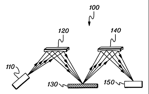
[0025] FIG. 1 shows one embodiment of an XRF/WDS system 100, in
accordance with an aspect of the present invention;
-6-
CA 02489646 2004-12-16
WO 02/103710 PCT/US02/19272
[0026] FIG. 2 shows a doubly curved crystal optic which provides point-to-
point focusing for use in a system in accordance with the present invention;
[0027] FIG. 3A shows one embodiment of the geometry of a doubly curved
logarithmic spiral crystal or mufti-layer optic for use in a system in
accordance
with the present invention;
[0028] FIG. 3B depicts a cross-sectional view of the optic of FIG. 3A taleen
along line B-B;
[0029] FIG. 4 depicts another embodiment of an XRF/WDS system 200, in
accordance with an aspect of the present invention; and
[0030] FIG. 5 shows a polycapillary optic which provides point-to-point
focusing, for use in a system in accordance with an aspect of the present
invention.
Best Mode for Carrying Out The Invention
[0031] Generally stated, one embodiment of a compact XRF/WDS system in
accordance with an aspect of the present invention comprises an x-ray source,
an
excitation x-ray optic that focuses x-rays onto a sample from the source, at
least one
collection monochromator and an x-ray counter. The excitation x-ray optic can
be a
focusing polycapillary optic that provides polychromatic excitation or a point-
focusing
doubly curved crystal optic that provides monochromatic excitation. The
collection
monochromator (which can be a doubly curved crystal optic, a doubly curved
multi-
layer optic, or other doubly curved diffracting optic) selects a desired
characteristic
wavelength of an element. The intensity of the reflected x-rays is measured by
a
detector and is correlated to the concentration of this element in the
specimen.
[0032] One aspect of an XRF/WDS system in accordance with the present
invention is that the excitation optic can efficiently capture a large cone
angle of x-
CA 02489646 2004-12-16
WO 02/103710 PCT/US02/19272
rays from a point x-ray source. This optic is a focusing optic which can
produce a
very intensive excitation beam'on the sample even with the use of a compact,
low-
power (e.g., <1KW, and more beneficially <100W) x-ray source. The use of a low-
power x-ray tube makes this system much more compact and simpler compared with
a
conventional XRFIWDS system using a bulky kw x-ray tube.
(0033] Another aspect of this invention is that a monochromatic excitation
beam
can be produced if a doubly curved crystal optic is used as the excitation
optic. In a
typical embodiment of an XRF/WDS system, a polychromatic beam is used to
excite
the sample. Monochromatic excitation gives much higher signal-to-background
ratio
than polychromatic excitation due to the elimination of the scattering
bremsstrablung
from the the x-ray source on the sample. This improves the detection limit of
the
system significantly. Monochromatic excitation also greatly simplifies the
quantitative analysis of XRF.
[0034] Still another aspect of this invention is that the excitation beam is
focused
on the sample because of the focusing capability of the excitation optic. The
focal
spot size of the beam on the sample may be in the range of 50~ to 500., which
is
about two orders of magnitude smaller that the beam size of a conventional
system
(which is typically ~lOmm-30mm). Besides providing efficient collection, this
smaller beam size allows spatial resolution in the analysis.
[0035] Due to the smaller sample excitation area, a doubly curved diffracting
optic
can be effiencently used as the collection optic (in another aspect of the
present
invention). Doubly curved monochromatic optics can provide large collection
solid
angles from a spot. (In a conventional XRF/WDS system with a large excitation
beam
size, a flat or singly curved monochromator is the choice and the collection
solid angle
is limited.) A doubly curved monochromator improves the signal level
considerably
for the detected element for a given geometry and intensity of the excitation
beam.
_g_
CA 02489646 2004-12-16
WO 02/103710 PCT/US02/19272
[0036] A further aspect of this invention is that the collection optic can be
fixed
relative to the sample and the detector, with no moving parts involved. This
could
have both advantage and disadvantage. An advantage would be that it speeds up
the
analysis and improves system reliability, while a disadvantage is that
multiple
collection optics may be necessary; for example, for mufti-element analysis.
[0037] To restate, in accordance with the principles of the present invention,
an
XRF/WDS system is described with x-ray focusing optics providing polychromatic
or
monochromatic excitation to a sample. Secondary x-rays that result from x-ray
fluorescence are collected by a monochromator, which comprises a doubly curved
diffractor, for forwarding to a detector such as a proportional counter, a
room
temperature PIN detector, or a NaI detector. One example of an XRF/WDS system
100 using such x-ray optics to provide monochromatic excitation and collect x-
rays
from the sample is described in detail below with reference to FIG. 1.
[0038] XRFIWDS system 100 includes, for example, a low power x-ray source
110, a monochromatic focusing optic 120, a sample 130, a collection
monochromator
140, and a detector 150.
[0039] Low power x-ray source 110 (e.g., <II~W, and more ideally <100W) is a
source of x-ray radiation such as an x-ray tube, a sealed source of
radioactive material,
or a source of high energy electrons that impinge upon a metal target and
produce x-
ray radiation. One example of low power x-ray source 110 is a SOW x-ray tube,
with a
target material comprising chrome, copper, tungsten, or molybdenum, and an
electron
beam size on the target material in the range of approximately SOpm to 300~.m.
[0040] Sample 130 is a material to undergo metrology measurements . An
example of sample 130 may be a process flow such as diesel fuel from which
measurement of the concentration of sulfur is desired, or lubricating oil from
which
measurement of the concentration of wear metal (iron) is desired. If sample
130 is a
-9-
CA 02489646 2004-12-16
WO 02/103710 PCT/US02/19272
fluid flow, a window material (not shown) may be included to enable
transmission of
x-ray excitation radiation into and x-ray fluorescence out of sample 130.
[0041] Monochromatic focusing optic 120, located between x-ray source 110 and
sample 130 of XRF system 100, serves to reflect or transmit only radiation
within a
small range of energies to sample 130, e.g. within a range of energies between
tens or
hundreds of electron-Volts, as opposed to polychromatic optics, which transmit
radiation with energy bandwidths in the thousands of electron-Volts. Optic 120
also
focuses the x-rays to a small focal spot on sample 130. The size of this focal
spot
may be in the range of SO~.m to SOO~.m.
[0042] One example of focusing optic 120 is a 3ohann type doubly curved
crystal.
An example of the geometry of a Johann type doubly curved crystal is shown in
Figure 2. In this geometry, the diffracting planes of the crystal 160 are
shown parallel
to the crystal surface. The crystal surface, which is a toroidal shape, has
the Johann
geometry in the plane of the focal circle 170 and axial symmetry along line
SI, where
point S is the location of the x-ray source 110 (FIG. 1) and point I is the
focal spot.
The crystal surface has a radius of curvature of 2R in the plane of the focal
circle and a
radius of curvature of ~Rsih2~B in the mid-plane perpendicular to segment SI,
where R
is the radius of the focal circle and BB is the Bragg angle. X-rays diverging
from point
S, and striking the crystal surface with incident angles within the rocking
curve width
of the crystal will be reflected efficiently to point I. This type of doubly
curved crystal
not only provides point focusing but also monochromatizing of beam 1 ~0 since
only
x-rays photons with the correct wavelength can be reflected.
[0043] As shown in FIG. 1, x-ray optic 140 is another monochromating optical
element of XRF system 100, and is located between sample 130 and detector 150.
This optic collects a specific wavelength of x-rays and directs the x-rays to
an x-ray
detector. In a conventional XRFlWDS system, a flat or singly-curved crystal
optic
might be the optic of choice. In the present invention, the collection
monochromator
-10-
CA 02489646 2004-12-16
WO 02/103710 PCT/US02/19272
is a doubly curved difFractor (e.g., a crystal or mufti-layer optic), which
can provide a
much larger collection solid angle from a point than can a flat/singly-curved
optic.
[0044] A specific example of a collection monochromatic optic 140 is a doubly
curved logarithmic spiral crystal optic. One embodiment of this geometry is
illustrated in FIGS. 3A & 3B. In this geometry, the diffraction planes of the
crystal
optic are parallel to the crystal surface. The crystal surface in the
dispersive plane has
the shape of a logarithmic spiral and a rotational symmetry about the axis ID,
where
point I is the origin of the log spiral and the focal point of the excitation
beam on the
sample 130 (FIG. 1), and point D is the location of the detector 150 (FIG. 1).
Fluorescence x-rays emitted from point I on the sample surface have a constant
incident angle on this logarithmic spiral surface due to the property of the
spiral curve.
This constant angle is selected to be the Bragg angle of the characteristic x-
rays of the
interested element in the sample 130 for the diffraction planes of the
crystal. The
reflected x-rays from the doubly curved log spiral geometry will not form to a
point,
but to a caustic in the dispersive plane. The x-rays will be focused on the
axis ID, as
shown in FIG. 3B, along the direction of ID.
[0045] Alternately, multilayer optics may be employed in the system of FIG. 1
for
monochromatic optic 120 and monochromatic optic 140. Detector 150 may be a
simple counting detector, namely, a gas proportional counter, a scintillation
counter, or
a room temperature PIN diode solid state detector.
[0046] Advantageously, XRF/WDS system 100 is well suited for high-sensitivity
trace elemental analysis. The point-to-point focusing doubly curved crystal
optic
provides a large collection solid angle and forms a very intense focusing
monochromatic beam on the sample even with the use of a low power x-ray tube.
Due
to the monochromatic excitation, the signal-to-background ratio is improved
significantly and the detection sensitivity is improved. Point focusing of the
excitation
beam onto the sample enables the efficient use of a doubly curved collection
optic to
11-
CA 02489646 2004-12-16
WO 02/103710 PCT/US02/19272
improve the collection solid angle of the fluorescence x-rays. This will
further
improve sensitivity of the system.
[0047] As one specific embodiment of XRF/WDS system 100 of FIG. 1, the
system could comprise an x-ray source 110 comprising a SOW x-ray tube with a
source material of chrome, copper, tungsten or molybdenum, and a spot size on
the
source material that is approximately 100~,m to 300~.m. The optic 120 may be a
doubly curved point focusing crystal that is fabricated from silicon,
germanium, or
other crystal materials and is located 100mm to 200mm from the x-ray source
110
along the optical axis, which is defined as the ray proceeding central from
the x-ray
source impinging upon doubly curved crystal 120 central to the doubly curved
crystal
120. The sample 130 may be oil, for example, with trace elements that may
include
sulfur, vanadium, and nickel. Sample 130 may be located 100mm to 200mm from
the
monochromatic optic 120 measured along the optical axis. Second monochromatic
optic 140 may be a doubly curved log spiral crystal that is fabricated from
silicon,
germanium, or other crystal materials, and is located 100mm to 200mm from
sample
130 measured along the optical axis. A detector 150 may be a gas proportional
counter, a scintillation counter, a room temperature PIN detector, or a NaI
detector and
be located 100mm to 200mm from the sample measured along the optical axis.
[0048] By adding one or more collection monochromators and detectors to system
100, two or more elements can be detected, with each collection monochromator
paired to a detector for a respective, single element detection.
[0049] FIG. 4 shows an alternative embodiment of an XRF system 200 in
accordance with an aspect of the present invention. System 200 includes a
source 210,
a polychromatic focusing optic 220, a sample 230, a doubly curved
monochromatic
optic 240, and a detector 250.
[0050] Polychromatic optic 220 is an optical element which transmits a broad
range of photon energies, while focusing the photons it collects to a small
spot on
-12-
CA 02489646 2004-12-16
WO 02/103710 PCT/US02/19272
sample 230. One example of a polychromatic optic that is well suited to
function as
optic 220 is a polycapillary optic 300 (see FIG. 5), such as available from X-
Ray
Optical Systems, of Albany, New York. A polycapillary optic, which is
described in
detail in many of the above-incorporated patents, is a bundle of thin, hollow
tubes that
transmit photons via total reflection.
[0051] Due to the polychromatic excitation, the signal-to-background ratio
will be
poorer than compared to that of system 100 (FIG. 1). However, system 200 (FIG.
4)
can provide several advantages. For example, with system 200 a smaller focal
spot
can be obtained due to the better focusing capability of a polycapillary
optic. This
may give better spatial resolution for local analysis. For example, a 20~,m to
SO~.m
focal spot can be obtained using a SOW x-ray tube and polycapillary optic.
Another
advantage is that polychromatic excitation provides x-ray photons with a wide
range
of energy that can cover almost all the elements in the periodic table.
[0052] In one specific embodiment, XRF/WDS system 200 may include an x-ray
source 210 which may be a SOW x-ray tube with a source material of chrome,
copper,
tungsten or molybdenum and a spot size on the target material that is
approximately
100~.m to 300wm. The polychromatic optic 220 may be a polycapillary optic
located
30mm to SOmm from x-ray source 210. The sample 230 may be, for example, oil
with
elements that may include sulfur, vanadium, and nickel. The sample 230 could
be
located 100mm to 200mm from polycapillary optic 220. Doubly curved
monochromator 240 may be a doubly curved log spiral crystal that is fabricated
from
silicon, germanium, or other crystal material and is located 100mm to 200mm
from
the sample 230 measured along the optical axis. Detector 250 could be is a gas
proportional counter, a scintillation counter, a room temperature PIN
detector, or a NaI
detector located 100mm to 200mm from the monochromatic optic 240 measured
along
the optical axis. Multiple collection monochromators with corresponding
detectors
could also be used for mufti-element detection.
-13-
CA 02489646 2004-12-16
WO 02/103710 PCT/US02/19272
[0053] Although preferred embodiments have been depicted and described herein,
it will be apparent to those skilled in the relevant art that various
modifications,
additions, substitutions and the like can be made without departing from the
spirit of
the invention as defined in the following claims.
- 14-