Note: Descriptions are shown in the official language in which they were submitted.
CA 02489652 2012-04-19
RF INDUCTION LAMP WITH REDUCED ELECTROMAGNETIC
INTERFERENCE
TECHNICAL FIELD
[0001] This invention relates to electrodeless fluorescent lamps and more
particularly to such
lamps having reduced electromagnetic interference (EMI) making them more
suitable
for the commercial and residential markets.
BACKGROUND ART
[0002] Electrodeless fluorescent lamps generally require mounting in a special
fixture designed
to shield the surrounding area from the EMI generated by the operation of the
lamp.
Such fixtures function as a Faraday shield and allow the lamp to operate
without too
much disturbance to adjacent devices; however, such special fixtures also
limit the
places where the lamps can be employed.
[0003] Several current lamps attempt to solve this problem by various means,
one of which
involves applying EMI screening to the lamp envelope in the form of a
transparent
conductive coating on the interior surface of the lens portion of the lamp
together with
an opaque metal coating on the outside surfaces of the sides of the lamp
envelope. The
coatings are connected electrically to the local ground of the lamp. This
system greatly
increases the cost of the lamp and reduces the lamp's efficiency and is really
only
suitable for PAR lamps.
[0004] Another approach, shown in U.S. Patent No. 4,710,678, involves the use
of a second
winding interspersed between the primary windings on the ferrite core of the
lamp. The
second winding has one free end and the other end connected to one end of the
primary
winding. Interference currents at the supply mains with this approach are
alleged to be
strongly suppressed.
-l-
CA 02489652 2012-04-19
[0005] It would be an advance in the art if the EMI of electrodeless
fluorescent lamps could be
further improved at reasonable cost to allow more usage in residential and
commercial
applications.
DISCLOSURE OF INVENTION
[0006] It is desirable to obviate one or more of the disadvantages of the
prior art.
[0007] It is also desirable to enhance electrodeless fluorescent lamps.
[0008] It is also desirable to enhance the efficiency of electrodeless
fluorescent lamps.
[0009] It is also desirable to provide a lamp design providing EMI-free
electrodeless
fluorescent lamps without employing the complicated screening means of the
prior art
lamps.
[0010] An electrodeless fluorescent lamp is disclosed having a lamp envelope
that includes a
chamber with core of magnetic material therein. A first winding surrounds the
core and
has a first hot lead-in wire attached to a high frequency end of the voltage
supply and a
second lead-in connected to the local ground of the RF voltage supply. A
second
winding surrounds the core, and respective turns of the second winding are
located
adjacent turns of the first winding and electrically insulated therefrom. The
second
winding has a free end and has another end connected to one of the grounded
lead-in
wires of the first winding. A grounded braided sheath surrounds the hot lead-
in wire of
the first winding. The first winding and the second winding are bifilar and
have equal
lengths. This construction improves the electrostatic symmetry of the lamp by
screening
the lead-in wire of the driven winding.
[0011] Also disclosed is an electrodeless fluorescent lamp having a lamp
envelope that includes
a chamber with a core of magnetic material therein. A first winding surrounds
the core
and has first and second lead-ins attached to a high frequency supply. A
second winding
-2-
CA 02489652 2012-04-19
surrounds the core with respective turns of the second winding located
adjacent turns of
the first winding and electrically insulated therefrom. The first winding and
the second
winding are bifilar and have equal lengths. One end of the second winding is
connected
to one of the lead-ins of the first winding. In this embodiment the two radio
frequency
windings (that is, the first and second windings) have equal lengths and equal
radio
frequency (RF) voltage but of opposite phase, thereby mutually canceling the
RF
coupling to the lamp body.
[0012] According to one aspect of the invention, there is provided an
electrodeless fluorescent
lamp wherein the improvement comprises: a lamp envelope including a chamber; a
core
of magnetic material in the chamber; a first winding surrounding the core and
having
first and second lead-in wires attached to a high frequency voltage supply;
and a second
winding surrounding the core, respective turns of the second winding being
located
adjacent turns of the first winding and electrically insulated therefrom, the
second
winding having a free end and having another end connected to one of the lead-
in wires,
the other of the lead-in wires being surrounded by a grounded braided sheath
disposed
entirely within the lamp adjacent the core of magnetic material.
[0013] According to another aspect of the invention, there is provided an
electrodeless
fluorescent lamp wherein the improvement comprises: a lamp envelope including
a
chamber; a core of magnetic material in the chamber; a first winding
surrounding the
core having first and second lead-ins attached to a high frequency supply; and
a second
winding surrounding the core, respective turns of the second winding being
located
adjacent turns of the first winding and electrically insulated therefrom, the
first winding
and the second winding being bifilar and having equal lengths, one end of the
second
winding being connected to one of the lead-ins of the first winding.
BRIEF DESCRIPTION OF THE DRAWINGS
[0014] Fig. 1 is a diagrammatic sectional view of an embodiment of the
invention;
-3-
CA 02489652 2012-04-19
[0015] Fig. 2 is a circuit diagram of the winding connection;
[0016] Fig. 3 is an enlarged view of the embodiment of Fig. 1;
[0017] Fig. 4 is a circuit diagram of the winding connection in an alternate
embodiment; and
[0018] Fig. 5 is a view of an alternate embodiment of the invention.
BEST MODE FOR CARRYING OUT THE INVENTION
[0019] For a better understanding of the present invention, together with
other and further
objects, advantages and capabilities thereof, reference is made to the
following
disclosure and appended claims taken in conjunction with the above-described
drawings.
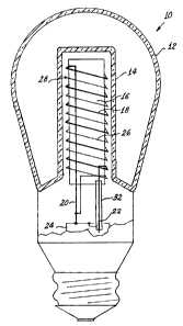
[0020] Referring now to the drawings with greater particularity, there is
shown in Fig. I an
electrodeless fluorescent lamp 10 having an envelope 12 that includes a
chamber 14. A
core 16 of magnetic material, preferably ferrite, is positioned in the chamber
14 and has
a first winding 18 surrounding the core and having first and second lead-in
wires 20, 22,
attached to a high frequency voltage supply or ballast 24. A second winding 26
surrounds the core 16, respective turns of the second winding 26 being located
adjacent
turns of the first winding 18 and electrically insulated therefrom. The second
winding 26
has a free end 28 and has another end 30 connected to one of the lead-in
wires, for
example 20. A braided sheath 32 (shown schematically in Fig. 2 and
diagrammatically
in Fig. 3) surrounds the other of the lead-in wires 22. The first winding 18
is generally
called the RF antenna. In the drawings the first winding 18 is shown as a
relatively thick
line and the second winding 26 is shown as a relatively thin line, the line
widths being
exemplary and for illustrative purposes only, the actual wires being
identical. The
braided sheath 32 is connected to the local ground. This inexpensive solution
alone
-4-
CA 02489652 2012-04-19
reduces the conductive EMI level sufficiently to pass all existing regulations
on such
interference with significant reserve.
[0021] An alternate solution is shown in Figs. 4 and 5, with Fig. 4 showing
the circuit
schematically and Fig. 5 showing the core and windings diagrammatically,
wherein the
core 16a of magnetic material has a first winding 18a surrounding the core 16a
and
having first and second lead-ins wires 20a and 22a attached to a high
frequency supply
24. In this instance the second winding 26a surrounding the core 16a,
respective turns of
the second winding being located adjacent turns of the first winding and
electrically
insulated therefrom, is bifilar, as is the first winding and the first winding
and the
second winding have equal lengths. Again, one end of the second winding 30a is
connected to one of the lead-ins, for example, 20a, of the first winding 18a.
The first and
second windings have opposite phase; thus, the two RF wires with equal length
and
equal RF voltage and opposite phase have a mutually canceled RF coupling to
the lamp
body. To preserve the electric symmetry in this embodiment it is essential to
keep the
lengths of the two lead-ins having opposite phase equal to each other in their
uncompensated parts. This is achieved by putting both leads together to form a
double
line in the middle of the ferrite core 16a, as is shown in Fig. 5.
[0022] Implementing either form of the two embodiments shown allows reduction
of the EMI
level in electrodeless fluorescent lamps up to and lower than regulations
permit for
commercial and residential applications without expensive shielding of the
entire lamp.
This allows the use of A-shape lamps with large surface areas to radiate
visible light and
results in a significant increase in lamp efficacy.
[0023] While there have been shown and described what are present considered
to be the
preferred embodiments of the invention, it will be apparent to those skilled
in the art that
various changes and modifications can be made herein.
-5-