Note: Descriptions are shown in the official language in which they were submitted.
CA 02489900 2004-12-13
FINNED JACKETS FOR LAN CABLES
BACKGROUND OF THE INVENTION
1. Field of the Invention
[001] The present invention relates to a cable employing a plurality of
twisted wire pairs. More particularly, the present invention relates to a
jacket for housing the plurality of twisted wire pairs, which reduces the
likelihood of transmission errors because of reduced alien crosstalk,
interference from an adjacent cable, and reduced signal attenuation, and
hence allows for a relatively higher bit rate transmission.
2. Description of the Related Art
[002] Along with the greatly increased use of computers for homes
and offices, there has developed a need for a cable, which may be used to
connect peripheral equipment to computers and to connect plural
computers and peripheral equipment into a common network. Today's
computers and peripherals operate at ever increasing data transmission
rates. Therefore, there is a continuing need to develop a cable, which can
operate substantially error-free at higher bit rates, but also satisfy
numerous elevated operational performance criteria, such as a reduction in
alien crosstalk when the cable is in a high cable density application. e.g.
routed alongside other cables.
1
CA 02489900 2004-12-13
(003] Figures 1-3 show cables in accordance with the background art.
Figure 1 is a perspective view of an end of a cable. Figure 2 is a cross
sectional view take along the line II-II in Figure 1. Figure 3 is a cross
sectional view, similar to Figure 2, but showing two cables immediately
adjacent to each other in a high cable density application.
[004] Figure 1 shows a cable M including four twisted wire pairs (a
first pair A, a second pair B, a third pair C and a fourth pair D) housed
inside of a common jacket J. In Figure 1, the jacket J has been partially
removed at the end of the cable M and the twisted wire pairs A, B, C and D
have been separated.
[005] Figure 2 shows the dynamics of the four twisted wire pairs A, B,
C and D inside the jacket J. The first twisted wire pair A continuously twist
about each other within a space defined by the dashed line a. The second
twisted wire pair B continuously twist about each other within a space
defined by the dashed line b. The third twisted wire pair C continuously
twist about each other within a space defined by the dashed line c. The
fourth twisted wire pair D continuously twist about each other within a
space defined by the dashed line d. As can be seen in Figure 2, each wire of
the twisted wire pairs A, B, C and D comes into contact with an inner
circumferential wall IW of the jacket J, as the wire twists along the length
of
the cable M. Also, Figure 2 illustrates a thickness t of the jacket J. A
typical
thickness t, which exists between the inner circumferential wall IW and an
outer circumferential wall OW of the jacket J is 22 mil.
2
CA 02489900 2004-12-13
(006] Figure 3 illustrates a first cable M 1 and a second cable M2, in
accordance with the background art, placed immediately adjacent to each
other. This arrangement is commonplace, especially in an office-networking
environment where hundreds of cables are fed through conduits in ceilings,
floors and walls into a networking closet for interconnections. As can be
seen in Figure 3, each wire of the twisted wire pairs A, B, C and D in the
first cable M 1 will, at times, be spaced from the wires of the twisted wire
pairs A, B, C and D in the second cable M2 by a distance 2t, or twice the
thickness t of the jacket J.
[OOT] The cables of the background art suffers drawbacks. Namely,
the background art's cable exhibits unacceptable levels of Alien Near End
Crosstalk (ANEXT) and Alien Far End Crosstalk (AFEXT), especially at
higher data transmission rates. To measure the ANEXT and AFEXT of the
pairs in a cable, an industry standard testing technique, making use of a
vector network analyzer (VNA), is employed.
[008] Briefly, an output of the VNA is connected to pair A of the
second cable M2 while an input of the VNA is connected to pair A of the first
cable MI. The VNA output sweeps over a band of frequencies, e.g. from
0.500 MHz to 1000 MHz, and the ratio of the signal strength detected on
pair A of the first cable M 1 over the signal strength applied to the pair A
in
the second cable M2 is read and recorded. This is the ANEXT or AFEXT
contributed to the pair A in the first cable M 1 from the pair A in the second
cable M2. Contributions to the pair A in first cable M 1 from the other pairs
B, C and D in the second cable M2 are acquired in the same manner.
3
CA 02489900 2004-12-13
[009] The contributions from the pairs A, B, C and D in second cable
M2 to the pair A in the first cable M 1 are summed and considered to be the
ANEXT and AFEXT performance for the pair A in cable M 1. The above
procedure is repeated for the second, third and fourth twisted wire pairs B,
C and D of the first cable M 1 to obtain the ANEXT and AFEXT for the
second, third and fourth pairs B, C and D. The difference between alien
near end crosstalk (ANEXT) and alien far end crosstalk (AFEXT) is that for
ANEXT, the signal output for the tested pair is read from the same end, e.g.
the near end, of the cable that the input sweeping test signals are applied.
For AFEXT, the signal output for the tested pair is read from the opposite
end, e.g. the far end, of the cable relative to the end into which the input
sweeping test signals are applied.
[010] The ANEXT and AFEXT performance is unacceptable in the
cables according to the background art because when the first cable M 1 and
the second cable M2 are placed immediately adjacent to each other, the
spacing 2t allows for cross capacitance / cross inductance between the
wires in the first cable M 1 and the wires in the second cable M2. This cross
capacitance and cross inductance results in particularly high levels of cross
talk, particularly as the data bit rates of transmission increase.
SUMMARY OF THE INVENTION
[011] One possible solution to this drawback would be to improve, i.e.
lower, the dielectric constant of the jacket material. Improving the
dielectric
4
CA 02489900 2004-12-13
material of the jacket would reduce cross capacitance and cross inductance
between the wires of the first cable M 1 and the wires of the second cable M2.
However, typical listing and code requirements set minimum smoke and/or
flame retardant standards for the cable. In order to surpass these minimum
standards, the materials typically used to form the jacket are PVC
compounds. Such compounds have inferior dielectric properties.
[012] Another possible solution would be to add a shielding layer
inside the jacket, surrounding the twisted wire pairs therein. This solution
greatly reduces the crosstalk between cables. However, adding a shielding
layer to a cable complicates the manufacturing process, changes the
telecommunication network to incorporate grounding and requiring different
interconnection components, and greatly increases the cost of the cable and
the network.
[013] Another possible solution would be to increase the thickness of
the jacket. It is understood that increasing the distance between two wires
carrying signals will reduce the cross capacitance / cross inductance, and
hence lower the crosstalk therebetween. However, this solution also suffers
drawbacks. Increasing the thickness of the jacket increases the costs of the
cable, the weight of the cable, and the rigidity of the cable. It also
increases
signal attenuation, reducing signal strength, associated with having more
material with a higher dielectric constant and dissipation factor surrounding
the plurality of twisted pairs. The added weight and rigidity make
installations more troublesome. Moreover, the presence of added jacket
CA 02489900 2004-12-13
material could cause the cable to fail smoke and/or flame tests, as more
material is present to smoke and or burn.
[014] A solution, in accordance with the present invention, addresses
one or more of the drawbacks associated with the background art, while
avoiding the additional drawbacks mentioned above.
[015] It is an object of the present invention to provide a cable with a
jacket configuration, which improves the alien crosstalk and attenuation
performance of the cable, as compared to existing cables.
[016] It is an object of the present invention to provide a cable with an
improved attenuation and crosstalk performance, which meets or surpasses
the minimum standards to qualify as a telecommunications cable, such as
UL Subject 444, and EIA/TIA 568.
[017] These and other objects are accomplished by a cable including a
plurality of conductors housed inside a jacket. . A plurality of protrusions
extends away from a circumferential surface of the jacket. The protrusion
may extend outwardly from an outer circumferential surface of the jacket, or
may extend inward from an inner circumferential surface of the jacket. The
protrusions ensure that the twisted wire pairs of one cable are well
distanced from the twisted wire pairs of another cable when two cables are
placed adjacent to one another. The cable can be designed to meet the
requirements of telecommunications cabling standards including UL Subject
444, and EIA/TIA 568 standards and demonstrates reduced attenuation
and crosstalk characteristics even at high data bit rates.
6
CA 02489900 2004-12-13
[018] Further scope of applicability of the present invention will
become apparent from the detailed description given hereinafter. However,
it should be understood that the detailed description and specific examples,
while indicating preferred embodiments of the invention, are given by way of
illustration only, since various changes and modifications within the spirit
and scope of the invention will become apparent to those skilled in the art
from this detailed description.
BRIEF DESCRIPTION OF THE DRAWINGS
[019] The present invention will become more fully understood from
the detailed description given hereinbelow and the accompanying drawings
which are given by way of illustration only, and thus, are not limits of the
present invention, and wherein:
(020) Figure 1 is a perspective view of an end of a cable having a
jacket removed to show four twisted wire pairs, in accordance with the
background art;
[021] Figure 2 is a cross sectional view taken along line II-II in Figure
l, in accordance with the background art;
[022] Figure 3 is a cross sectional view similar to Figure 2, but
showing two cables immediately adjacent to each other in a high cable
density application, in accordance with the background art;
[023] Figure 4 is a cross sectional view of a cable having triangular-
shaped outwardly extending protrusions on an outer circumferential wall of
the cable's jacket;
CA 02489900 2004-12-13
[024] Figure 5 is a cross sectional view of four adjacent cables,
constructed in accordance with Figure 4;
[025] Figure 6 is a cross sectional view of a cable having rectangular-
shaped outwardly extending protrusions on an outer circumferential wall of
the cable's jacket;
[026] Figure 7 is a cross sectional view of four adjacent cables,
constructed in accordance with Figure 6;
[027] Figure 8 is a cross sectional view of a cable having triangular-
shaped inwardly extending protrusions on an inner circumferential wall of
the cable's jacket, in accordance with the present invention;
[028] Figure 9 is a cross sectional view of four adjacent cables,
constructed in accordance with Figure 8;
[029] Figure 10 is a cross sectional view of a cable having rectangular-
shaped inwardly extending protrusions on an inner circumferential wall of
the cable's jacket, in accordance with the present invention; and
[030] Figure 11 is a cross sectional view of four adjacent cables,
constructed in accordance with Figure 10.
DETAILED DESCRIPTION OF A PREFERRED EMBODIMENT
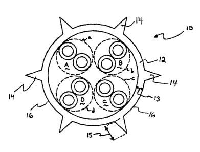
[031] Figure 4 is a cross sectional view of a cable 10, in accordance
with a first embodiment of the present invention. The cable 10 includes the
first, second, third and fourth twisted wire pairs A, B, C and D, which are
the same or similar to the twisted Wire pairs illustrated in Figures 1-3.
8
CA 02489900 2004-12-13
[032] The cable 10 includes a jacket 12. The jacket I2 may be formed
of a smoke or fire retardant material, such as a PVC compound. A thickness
13 of the jacket 12 is preferably about 20 mils.
[033] A plurality of protrusions 14 is formed on an outer
circumferential wall 16 of the jacket 12. The protrusions 14 have a
triangular shape and a thickness 15, which is preferably about 30 mils. The
protrusions 14 extend radially outward, away from a center of the cable 10.
The protrusions 14 may be integrally formed with the jacket 12 during an
initial extrusion process to form the jacket 12.
[034] Although Figure 4 illustrates six protrusions 14 integrally
formed with the jacket 12, it should be noted that more or Iess protrusions
14 may be included. For example, a cable 10 with ten or more protrusions
14, such as twelve, eighteen or nineteen protrusions 14 would equally serve
the advantages of the present invention. Moreover, other known materials,
besides PVC compounds, can be employed in the construction of the jacket
12. Also, the dimensions of the jacket's thickness 13 and each protrusion's
thickness 15 are given by way of example only. Other values may be chosen
for the jacket's thickness 13 and the protrusion's thickness 15, and are
considered to be within the purview of the present invention.
[035] Figure 5 is a cross sectional view illustrating four cables 10
placed immediately adjacent to each other. Such a configuration would
occur when four cables 10 are ran through a common conduit on the way to
or from a network connection closet in an office environment. As can be
seen in Figure 5, the protrusions 14 of the cables 10 engage the outer
circumferential walls 16 of the other cables 10. The engagement ensures a
9
CA 02489900 2004-12-13
minimum spacing 17 between the twisted wire pairs A, B, C and D within
one of the cables 10 and the twisted wire pairs A, B, C and D in another of
the cables 10. The spacing 17 is ensured to be greater than the thickness
15 of the protrusion I4 plus twice the thickness 13 of the jacket 12.
[036] By the present invention, the alien crosstalk performance of the
cable 10 is greatly improved without the expense of providing a dedicated
shielding layer. Further, the crosstalk performance is improved without
having to resort to more expensive materials to form the jacket, which might
have a lower dielectric value at the expense of poorer performance in a
smoke or flame test. Furthermore, the spacing between the cables is
increased without increasing an overall thickness of the jacket, thereby
keeping the weight, rigidity and material volume of the jacket to a minimum.
By the present invention, the attenuation performance of the cable 10 is
greatly improved along with alien crosstalk since air with a lower dielectric
constant and dissipation factor substance is incorporated into the jacket
continuum. Having air next to the twisted pair has the greatest impact in
improving attenuation.
[037] Figure 6 is a cross sectional view of a cable 20, in accordance
with a second embodiment of the present invention. The cable 20 includes
the first, second, third and fourth twisted wire pairs A, B, C and D, which
are the same or similar to the twisted wire pairs illustrated in Figures 1-3.
[038] The cable 20 includes a jacket 22. The jacket 22 may be formed
of a smoke or fire retardant material, such as a PVC compound. A thickness
23 of the jacket 22 is preferably about 20 mils.
CA 02489900 2004-12-13
(039] A plurality of protrusions 24 is formed on an outer
circumferential wall 26 of the jacket 22. The protrusions 24 have a
rectangular shape and a thickness 25, which is preferably about 30 mils.
The protrusions 24 extend radially outward, away from a center of the cable
20. The protrusions 24 may be integrally formed with the jacket 22 during
an initial extrusion process to form the jacket 22.
[040] Although Figure 6 illustrates six protrusions 24 integrally
formed with the jacket 22, it should be noted that more or less protrusions
24 may be included. For example, a cable 20 with ten or more protrusions
24, such as twelve, eighteen or nineteen protrusions 24 would equally serve
the advantages of the present invention. Moreover, other known materials,
besides PVC compounds, can be employed in the construction of the jacket
22. Also, the dimensions of the jacket's thickness 23 and each protrusion's
thickness 25 are given by way of example only. Other values may be chosen
for the jacket's thickness 23 and the protrusion's thickness 25, and are
considered to be within the purview of the present invention.
[041] Figure 7 is a cross sectional view illustrating four cables 20
placed immediately adjacent to each other. Such a configuration would
occur when four cables 20 are ran through a common conduit on the way to
or from a network connection closet in an office environment. As can be
seen in Figure 7, the protrusions 24 of the cables 20 engage the outer
circumferential walls 26 of the other cables 20. The engagement ensures a
minimum spacing 27 between the twisted wire pairs A, B, C and D within
one of the cables 20 and the twisted wire pairs A, B, C and D in another of
11
CA 02489900 2004-12-13
the cables 20. The spacing 27 is ensured to be greater than the thickness
25 of the protrusion 24 plus twice the thickness 23 of the jacket 22.
[042) By the present invention, the crosstalk performance of the cable
20 is greatly improved without the expense of providing a dedicated
shielding layer. Further, the crosstalk performance is improved without
having to resort to more expensive materials to form the jacket, which might
have a lower dielectric value at the expense of poorer performance in a
smoke or flame test. Further, signal attenuation is reduced associated with
the inclusion of air with a lower dielectric value into the jacket continuum.
Furthermore, the spacing between the cables is increased without increasing
an overall thickness of the jacket, thereby keeping the weight, rigidity and
material volume of the jacket to a minimum.
(043) Figure 8 is a cross sectional view of a cable 30, in accordance
with a third embodiment of the present invention. The cable 30 includes the
first, second, third and fourth twisted wire pairs A, B, C and D, which are
the same or similar to the twisted wire pairs illustrated in Figures 1-3.
[044) The cable 30 includes a jacket 32. The jacket 32 may be formed
of a smoke or fire retardant material, such as a PVC compound. A thickness
33 of the jacket 32 is preferably about 20 mils.
[045) A plurality of protrusions 34 is formed on an inner
circumferential wall 36 of the jacket 32. The protrusions 34 have a
triangular shape and a thickness 35, which is preferably about 20 mils. The
protrusions 34 extend radially inward, toward a center of the cable 30. The
protrusions 34 may be integrally formed with the jacket 32 during an initial
extrusion process to form the jacket 32.
12
CA 02489900 2004-12-13
[046] Although Figure 8 illustrates eight protrusions 34 integrally
formed with the jacket 32, it should be noted that more or less protrusions
34 may be included. For example, a cable 30 with ten or more protrusions
34, such as twelve, eighteen or nineteen protrusions 34 would equally serve
the advantages of the present invention. Moreover, other known materials,
besides PVC compounds, can be employed in the construction of the jacket
32. Also, the dimensions of the jacket's thickness 33 and each protrusion's
thickness 35 are given by way of example only. Other values may be chosen
for the jacket's thickness 33 and the protrusion's thickness 35, and are
considered to be within the purview of the present invention.
[047] Figure 9 is a cross sectional view illustrating four cables 30
placed immediately adjacent to each other. Such a configuration would
occur when four cables 30 are ran through a common conduit on the way to
or from a network connection closet in an office environment. As can be
seen in Figure 9, the protrusions 34 of the cables 30 engage the twisted wire
pairs A, B, C and D inside the cable 30 and create an effective inner
diameter 38 within the inner circumferential wall 36 of the jacket 32. The
twisted wire pairs A, B, C and D are no longer pressed against the inner
circumferential wall 36. Rather, the twisted wire pairs A, B, C and D are
engaged and held a distance away from the inner circumferential wall 36
equal to the thickness 35 of the protrusions 34.
[048] The engagement ensures a minimum spacing 37 between the
twisted wire pairs A, B, C and D within one of the cables 30 and the twisted
wire pairs A, B, C and D in another of the cables 30. The spacing 37 is
13
CA 02489900 2004-12-13
ensured to be greater than twice the thickness 35 of the protrusions 34 plus
twice the thickness 33 of the jacket 32.
[049) By the present invention, the crosstalk performance of the cable
30 is greatly improved without the expense of providing a dedicated
shielding layer. Further, the crosstalk performance is improved without
having to resort to more expensive materials to form the jacket, which might
have a lower dielectric value at the expense of poorer performance in a
smoke or flame test. Further, signal attenuation is reduced associated with
the inclusion of air with a lower dielectric value into the jacket continuum.
Furthermore, the spacing between the cables is increased without increasing
an overall thickness of the jacket, thereby keeping the weight, rigidity and
material volume of the jacket to a minimum.
[050) Figure 10 is a cross sectional view of a cable 40, in accordance
with a fourth embodiment of the present invention. The cable 40 includes
the first, second, third and fourth twisted wire pairs A, B, C and D, which
are the same or similar to the twisted wire pairs illustrated in Figures 1-3.
[051) The cable 40 includes a jacket 42. The jacket 42 may be formed
of a smoke or fire retardant material, such as a PVC compound. A thickness
43 of the jacket 42 is preferably about 20 mils.
[052) A plurality of protrusions 44 is formed on an inner
circumferential wall 46 of the jacket 42. The protrusions 44 have a
rectangular shape and a thickness 45, which is preferably about 20 mils.
The protrusions 44 extend radially inward, toward a center of the cable 40.
The protrusions 44 may be integrally formed with the jacket 42 during an
initial extrusion process to form the jacket 42.
14
CA 02489900 2004-12-13
[053] Although Figure 10 illustrates eight protrusions 44 integrally
formed with the jacket 42, it should be noted that more or less protrusions
44 may be included. For example, a cable 40 with ten or more protrusions
44, such as twelve, eighteen or nineteen protrusions 44 would equally serve
the advantages of the present invention. Moreover, other known materials,
besides PVC compounds, can be employed in the construction of the jacket
42. Also, the dimensions of the jacket's thickness 43 and each protrusion's
thickness 45 are given by way of example only. Other values may be chosen
for the jacket's thickness 43 and the protrusion's thickness 45, and are
considered to be within the purview of the present invention.
j054] Figure 11 is a cross sectional view illustrating four cables 40
placed immediately adjacent to each other. Such a configuration would
occur when four cables 40 are ran through a common conduit on the way to
or from a network connection closet in an office environment. As can be
seen in Figure 11, the protrusions 44 of the cables 40 engage the twisted
wire pairs A, B, C and D inside the cable 40 and create an effective inner
diameter 48 within the inner circumferential wall 46 of the jacket 42. The
twisted wire pairs A, B, C and D are no longer pressed against the inner
circumferential wall 46. Rather, the twisted wire pairs A, B, C and D are
engaged and held a distance away from the inner circumferential wall 46
equal to the thickness 45 of the protrusions 44.
[055] The engagement ensures a minimum spacing 47 between the
twisted wire pairs A, B, C and D within one of the cables 40 and the twisted
wire pairs A, B, C and D in another of the cables 40. The spacing 47 is
CA 02489900 2004-12-13
ensured to be greater than twice the thickness 45 of the protrusions 44 plus
twice the thickness 43 of the jacket 42.
[056] By the present invention, the crosstalk performance of the cable
40 is greatly improved without the expense of providing a dedicated
shielding layer. Further, the crosstalk performance is improved without
having to resort to more expensive materials to form the jacket, which might
have a higher dielectric value at the expense of poorer performance in a
smoke or flame test. Furthermore, the spacing between the cables is
increased without increasing an overall thickness of the jacket, thereby
keeping the weight, rigidity and material volume of the j acket to a minimum.
37.
[057] The various embodiments of the above-described cable can be
formed by extruding the dielectric material, forming the jacket and
protrusions, onto the twisted wire pairs. More specifically, first, second,
third and fourth twisted wire pairs are twisted about each other to form a
core strand. The core strand is stored on a first spool.
[058] Later, the core strand is deployed from the first spool into an
extrusion machine. The core strand passes though an opening in the
machine, around which the dielectric material is extruded. In conventional
operations, the extruded jacket has an overall circular cross sectional shape.
However, in the present invention, the conventional extrusion plate, causing
the circular cross sectional shape, is replaced by an extrusion plate causing
the complex cross sectional shape, with protrusions. After the extrusion
process, the cable is passed through a liquid cooling bath, through a drying
16
CA 02489900 2004-12-13
process, a printing process (to print cable indicia on the outer walls of the
jacket), and onto a second or take-up spool.
[059] As disclosed above, a cable constructed in accordance with the
present invention shows a high level of immunity to alien NEXT and FEXT,
which translates into a cabling media capable of faster data transmission
rates and a reduced likelihood of data transmission errors.
[060] The invention being thus described, it will be obvious that the
same may be varied in many ways. Such variations are not to be regarded
as a departure from the spirit and scope of the invention, and all such
modifications as would be obvious to one skilled in the art are to be included
within the scope of the following claims.
17