Note: Descriptions are shown in the official language in which they were submitted.
CA 02489927 2004-12-22
FOUNDATION WALL SYSTEM
Technical Field
The present invention relates generally to the field of construction panels
for walls and other structures. In particular, the present invention is
directed to a
wall panel system that is suitable for a wide variety of applications where
structural
strength, moisture resistance, and insulation values are especially important.
Examples of such applications are foundation walls and basement walls.
Background Art
One of the most demanding applications for building materials is use in
foundation or basement walls. Such walls structures are subject to the weight
of
the building (weight tangential to the surface of the wall, or shear forces),
as well
as the weight of the surrounding ground, which exerts forces normal to the
wall or
wall panels. Besides the structural demands, such walls and the materials
constituting them must be reasonably water-resistant, and preferably have a
reasonably high insulating value (R value).
Standard residential and light commercial foundations are made of
concrete-based products in a variety of different forms and embodiments. One
embodiment is manufactured on the building site in the form of poured
concrete.
Another popular variation is pre-shaped and furnace-fired blocks (commonly
called cinder blocks), which are manufactured at a factory and sent to a
building
site to be assembled using mortar and other well-known techniques. Foundation
walls of this nature have been used since ancient times. These types of
structures
have had wide acceptance, and have enjoyed apparent success in a number of
variations and embodiments. Some examples are described below.
One variation of a foundation wall is found in U.S. Patent
Number 4,856,939 to Hilfiker, issued August 15, 1989. In this patent, a
retaining
wall, to withstand a mass of earth, relies on polymer geogrids for
reinforcement
and wire trays to provide a solid face against the adjacent earth, which is to
be held
in place. The wire trays are L-shaped with intersecting floor and face
sections.
Hooked extensions formed on the face sections serve to secure the trays in a
superimposed relationship to hold the geogrids in place against the trays. The
geogrids extend distally from the trays to
CA 02489927 2004-12-22
-2-
provide deep reinforcement. While the necessary structural strength is
obtained to form a proper retaining wall, the techniques and materials are not
appropriate for a foundation wall, as used in a dwelling, also the retaining
wall of
Hilfiker, cannot maintain the integrity of a structure or building resting on
that
wall. Nor is the retaining wall of Hilfiker appropriate for preventing the
migration
of moisture, or maintaining a reasonable R factor.
The structural integrity to withstand the normal stresses incurring for a
foundation wall or retaining wall is provided by open-mesh structural textiles
in
U.S. Patent Number 6,056,479 to Stevenson, et al. A structural textile is
formed
from at least two and preferably three components. The first component or load-
bearing member is a high tenacity, high modulus, and low elongation yam. The
yarn can be either monofilament or multifilament. The second component is a
polymer in the form of a yarn or other form, which will encapsulate and bond
yarn
at the junctions to strengthen the junctions. The third component is an
optional
effect or bulking yarn. In the woven structural textile, a plurality of warp
yarns are
woven with a plurality of weft (filling) yarns. The weave is preferably a half-
crossed or full-crossed leno weave. The high structural integrity is provided
in a
wide variety of different shapes and applications and can withstand high
normal
stresses. However, open mesh structural textile is not suitable as a
foundation wall
material since substantial support for the structural textile is still
required. Further,
there is no moisture integrity or R factor provided by the structural textile.
Overall structural integrity apparently appropriate for a foundation wall is
provided by the system of U.S. Patent Number 6,041,561 to LeBlang , issued
March 28, 2000. This system relies upon pre-fabricated, self-contained
building
panels, including a panel incorporating a truss structure as a part thereof.
The
panels include a skeletal assembly generally comprising an array of structural
steel
channels, rigid sheeting arranged proximate to the channels, and support
members
adjacent the rigid sheeting. The channels are supported between suitable base
plates. The structure further includes angles for defining portions of the
skeletal
assembly and a forming structure, which is used as part of the skeletal
assembly.
The skeletal assembly and forming structure are
CA 02489927 2004-12-22
-3-
oriented horizontally on a plane or surface. A self-hardening material, such
as concrete, clay, or the like, is introduced to the forming structure for the
embedding at least a portion of the skeletal assembly. The forming structure
becomes an intrical part of the completed building panel, and is not removed
therefrom. A building truss, including a pair of double-angle struts and a web-
reinforcement bar threaded there along, and rigid sheeting are arranged to
define a
receiving chamber for the self-hardening material.
The self-contained building panels can be made entirely at a factory for
shipment in large segments to building sites, or the panels can be formed by
pouring the concrete into the appropriate portions of the panels at the
building site.
It should be noted that large wall segments that are formed entirely at the
factory
are problematical due to the weight of the concrete. Using an alternarive
method
of pouring the concrete at the building site introduces problems of quality
control
and uniformity. Further, the LeBlan~ system appears to be entirely subjected
to
the limitations imposed by the characteristics of concrete.
There are a number of limitations to poured concrete or cinder block
foundation walls. Despite its strength in compression, cinder block and even
poured concrete walls fail due to constantly changing load factors brought on
from
drastic temperature changes (in conjunction with water migration into the wall
material), water-saturated soil, soil shifting, and shock waves from external
disruptions transmitted through the ground to the foundation wall. One source
of
shock waves is earthquakes. Other examples would include explosive forces
(both
deliberate and accidental), as well as massive shifts in nearby ground
structure, due
to clumsy construction techniques. Soil is essentially a slow-moving fluid,
which
is always shifting. As a result, there are constantly changing forces working
on
any foundation wall.
Concrete and cinder block walls that are inundated by water are seldom
able to resist the penetration of moisture. Moisture migration introduces the
possibility of toxic mold occurring in residential buildings. This becomes a
critical
factor in obtaining insurance coverage, which is often denied for residential
structures having moldy interiors. Further, if the water remains standing
around
the wall, and freezes, structural failure certainly occurs. As a further
complication,
CA 02489927 2004-12-22
-4-
concrete has uneven drying characteristics. This results in varying strengths
throughout a poured concrete wall.
The molecular consistency of concrete is coarse. As a result, concrete has
very little insulating value. Further, concrete absorbs, retains and wicks
water to
the interior of the structure that includes the foundation wall. This tendency
is
even more pronounced with cinder block. Just as moisture vapor can penetrate a
concrete wall, so does Radon gas. This is particularly problematical in
certain
areas of Radon occurrence. A sufficient number of high Radon areas exist so
that
Radon has become the second leading cause of cancer in the United States. This
factor becomes particularly critical in basements used as exercise rooms since
heavy breathing increases the likelihood of Radon intake.
Poured concrete for building foundation walls is expensive, complicated,
and time-consuming. Less expensive alternatives, such as cinder blocks, are
widespread. However, the use of cinder block has its limitations. For example,
skilled masons are necessary to erect any structure using cinder block, and
additional treatment of the wall (such as filling the holes in the blocks) are
often
necessary to provide minimum standards of insulation, structural strength, and
resistance to moisture migration. Further, because mortar is used throughout a
cinder block wall, the wall loses flexibility that might have been provided by
the
use of multiple pieces as opposed to solid slab of concrete.
Both types of foundation wall fracture under a variety of loads that may
introduce tensile stress at various points along the wall. Further, the fact
that
poured concrete foundations and cinder block foundation walls are fabricated
at the
building site by individuals of varying degrees of skill results in non-
uniformity of
structure, and higher rates of failure than would result from unifornfly
manufactured building panels subject to the quality control standards of a
factory.
Another drawback of concrete foundation walls is its very low insulation
capability or R factor, usually in the range of 1.4 to 3Ø Consequently,
additional
insulation must be added to foundation walls. This is expensive, complex, and
time-consuming.
Even more detrimental is the damage to wooden structures supported by
such foundation walls. The passage of moisture through concrete foundation
CA 02489927 2004-12-22
-5-
walls dissipates through the rest of the structure, degrading wooden
structural
parts. The moisture can attack conventional structures in a number of ways,
including: expansion damage in buildings in locations which are subject to
freezing
temperatures, opening paths for insects introducing mold problems, increasing
the
possibility of Radon gas occurrence, and degrading thermal insulation.
As a result of some of the aforementioned problems, many modem wooden
structures have severely limited usable lifetimes. Accordingly, framed
structures
on concrete or cinder block foundations have to be replaced relatively
frequently.
A superior foundation wall system would eliminate all of the
aforementioned disadvantages of conventional foundation wall systems, and
would
extend the lifetimes of the structures placed on those foundation walls. A
desirable, improved foundation wall system would provide far greater tensile
strength (and thus overall strength) than conventional poured concrete or
cinder
block walls, as well as providing a good R factor and impermeability to
moisture.
Preferably, the improved foundation wall system would have a much greater
capability to withstand earthquake forces than conventional foundation wall
systems.
Summary Of Invention
It is a first object of the present invention to overcome the drawbacks of
conventional foundation or basement wall systems.
It is another object of the present invention to provide a foundation wall
system that is substantially impermeable to the migration of moisture.
It is a further object of the present invention to provide a foundation wall
system that is substantially impermeable to gasses, in particular Radon.
It is an additional object of the present invention to provide a foundation
wall system that is capable of withstanding substantial tensile stress, at a
level that
would destroy conventional concrete or masonry walls.
It is still another object of the present invention to provide a foundation
wall system that can withstand both high sheer and normal stresses without
failure.
CA 02489927 2004-12-22
-6-
It is yet a further object of the present invention to provide a foundation
wall system capable of effectively flexing while remaining highly resistant to
any
kind of penetration.
It is again an additional object of the present invention to provide a
foundation wall having a virtually unlimited longevity, and capable of adding
to
the longevity of any structure supported by the subject foundation wall.
It is yet another object of the present invention to provide a foundation wall
having high insulating (R factors) as part of its constituent materials
without the
necessity of adding extensive insulation to the foundation wall.
It is again a further object of the present invention to provide a foundation
wall system which readily admits to modification so that it can be adapted to
have
a much higher insulating value than in its original state.
It is yet an additional object of the present invention to provide a
foundation wall system that is virtually invulnerable to cracking or permanent
warping.
It is still a further object of the present invention to provide a foundation
wall that is highly earthquake or explosion resistant.
It is still an additional object of the present invention to provide a
foundation wall system that is relatively attractive when exposed above
ground.
It is yet another object of the present invention to provide a foundation wall
system that is relatively light in weight (when compared to similar masonry
wall
systems), so that large segments can be easily transported and assembled.
It is still a further object of the present invention to provide a foundation
wall system that is easily manufactured in large segments away from the
construction site where the foundation wall is being installed.
It is again another object of the present invention to provide a foundation
wall system that is relatively easy to install, requiring little skilled
labor.
It is yet a further object of the present invention to provide a foundation
wall system that is relatively inexpensive.
It is again another object of the present invention to provide a foundation
wall system that can be assembled very quickly in comparison to conventional
masonry wall systems.
CA 02489927 2004-12-22
-7-
It is still a further object of the present invention to provide a foundation
wall system with an integrated drainage mechanism that requires no further
installation work once the foundation wall is installed.
It is yet another object of the present invention to provide a foundation wall
system with a drainage devise that is configured for easy attachment between
foundation wall segments.
It is still an additional object of the present invention to provide a
foundation wall system with a drainage mechanism that is uniform along the
entire
length of the foundation wall.
It is again another object of the present invention to provide a foundation
wall system with a drainage device that prevents pooling or accumulation of
moisture anywhere along the length of the foundation wall system.
It is yet a further object of the present invention to provide a foundation
wall system with an integral conduit system for conducting wires, fiber
optics, and
the like.
It is again another object of the present invention to provide a foundation
wall system with an integral conduit system, which is adjustable to a variety
of
configurations for containing and separating wires, fiber optics, and the
like.
It is still a further object of the present invention to provide a foundation
wall system with an integral conduit system through which cables can be easily
pulled.
It is yet another object of the present invention to provide a wall system
having an integral conduit system that can be arranged at a variety of
locations on
the wall system.
It is again a further object of the present invention to provide a wall system
having an integral conduit which is easily adaptable to a number of different
corner
configurations in the wall system.
It is still a further object of the present invention to provide retrofitting
techniques to improve existing walls.
It is again another object of the present invention to provide an integrated
foundation wall system that can accommodate temperature-induced creepage
without permanent deformation.
CA 02489927 2004-12-22
-g-
These and other objects and goals of the present invention are
accomplished by a first embodiment, including a system of at least one
polyolefin
structural panel arranged to connect at least partially to a support for an
overlying
structure.
Another aspect of the present invention includes a foundation wall system
having a rigid barrier arranged to stop moisture migration through the
foundation
wall system.
A further aspect of the present invention is manifested by a foundation wall
system having a rigid barrier for stopping Radon gas nligration through the
foundation wall system.
An additional aspect of the present invention is manifested by a structural
panel, including two layers of polyolefin on either side of a glass fiber
layer.
Yet a further aspect of the present invention is manifested by a foundation
wall system including at least one structural panel having three layers bonded
together by plastic along a periphery of the structural panel. The structural
panel is
connected to a framework.
Another aspect of the present invention is a drainage system for use with a
foundation wall which is arranged on a footer. The drainage system includes a
substantially rectangular channel and a plastic membrane attached to the
channel
and arranged to fit over the footer.
Still another aspect of the present invention is found in a conduit system for
a framework wall. The conduit system includes at least one straight plastic
channel and at least one curved plastic channel.
Brief Description of Drawings
Figure 1 is a side cross-sectional view of the structural panel of the present
invention.
Figure 2 is a side cross-sectional view of the inventive wall system using
the panel of Figure 1.
Figure 3A is a bottom view of Figure 2.
Figure 3B is a side-cross-sectional view depicting details of Figure 2.
CA 02489927 2004-12-22
-9-
Figure 4 is a side-cross-sectional view of Figure 2, depicting additional
details.
Figure 5 is an exploded diagram of a corner section of the inventive conduit
system incorporated into the inventive wall system.
Detailed Description of Preferred Embodiments
The most basic aspect of the present invention is the use of a plastic panel
as a structural panel, such as those used to constitute foundation walls. Such
walls,
as described supra, must be capable of withstanding contact with the earth
around
the structure while still supporting that structure. Consequently, foundation
walls
are subject to both shear forces (from the weight above) and normal forces
(from
the weight of the earth against the wall). In the present invention, extruded
polyolefin sheets are used to construct foundation walls that support
overlying
structures, withstand the weight of the earth, and prevent moisture migration
through the foundation.
One particularly useful aspect of the present invention is that the extruded
polyolefin panels can be retrofitted to existing masonry walls, provide
waterproofing, resistance to impact, and higher insulation value. A number of
different methods can be used to connect polyolefin panels to existing masonry
walls, including adhesives, plastic welding to other plastic structures on the
existing wall, and the use of through-connectors. The holes made in the
polyolefin
panels by these connectors are easily sealed by the use of plastic welding.
Extruded polyolefin sheets can also be used along existing wooden walls,
to provide higher insulation value, impact resistance, and to help support any
other
structures supported by the existing wooden wall. While any number of
polyolefin
materials can be used for such structural panels, the material considered most
desirable as part of the present invention is a high density polyethylene such
as
PaxonTm (ExxonMobil Chemical Company, USA).
An extruded sheet of a polyolefin, in particular a high density polyethylene
such as PaxonTm(from 1/4 inch to 1 inch), is a superior structural material
for use
in structural panels in foundation walls and the like. Using only the basic
test
results for small pieces of a high density polyethylene such as PaxonTm,
CA 02489927 2004-12-22
-10-
calculations for large extruded sheets, such as those that would be used in
structural applications, have been developed as the preliminary work for the
present invention. Our calculations indicate that the strength of the sheets
is far
greater than that of much larger masses of poured concrete or cinder block.
While
the strength of high density polyethylenes such as Paxonrm are already well
known, there has not been any consideration for using extruded high density
polyethylenes such as Paxon'rM panels as a structural element in foundation
walls
and the like.
Another preferred aspect of the present invention is a structural panel
constituted by three layers. The two outer layers are polyolefin sheets (high
density, high molecular weight polyolefin such as a high density polyethylene)
with a center layer constituted by glass fiberboard. This sandwich arrangement
for
the structural board 1 is depicted in Figure 1. Layer 3 of a glass fiberboard
is
sandwiched between layers 2a and 2b of polyolefin sheets. The periphery of the
panel is preferably sealed by a plastic layer 4 which can be applied by
standard
plastic thermal-welding techniques known to those skilled in the art. These
structural panels can be used in a variety of different applications, and in
particular,
foundation or basement wall systems. A wall made with the structural panel
sandwich 1 is far superior in many respects to conventional poured concrete,
or
other masonry walls.
Such structural panels 1 are extremely hard (due to the characteristics of
polyolefins, particularly high density polyethylenes such as Paxonl?"),
resisting
impacts that would crumple cinderblocks. Also, the structural panels can be
made
in large segments, which would be impossible for preformed concrete and
extremely expensive to duplicate using cinderblock walls. The structural
panels
are light, and easy to transport, as well as assemble. As a result,
substantial
savings in labor cost can be achieved when using structures made from the
subject
structural panel 1. The strength of the structural panels also extends to
shear
forces, such as those that would be developed by weight resting on the panels
when
they are used as foundation or basement walls. Further, while concrete and
masonry have little strength in tension, the structural panels 1 of the
present
invention have extremely high tensile strength due to the nature of the
polyolefin
CA 02489927 2004-12-22
-11-
making up the structural panels 1. As a result, the structural panels I can be
used
to provide a high level of earthquake or blast resistance in foundation walls,
or the
walls of any other structure. Polyolefins are extremely resilient, and can
flex
without permanent deformation.
A key advantage of the inventive structural panels is that they are virtually
impermeable to the migration of moisture, as well as the migration of many
gasses
(when the adjoining panels are properly welded together). Thus the use of
these
panels in basement or underground walls is highly desirable since the
migration of
Radon gas is prevented when the wall panels are properly welded together. The
relatively high insulating value of the panels also make them particularly
desirable
in basement or underground walls, as well as many other types of walls.
Not only can the inventive structural panel 1 of the present invention be
used in foundation and basement walls, it can also be used in any structural
application where lightweight, high strength, and impermeability to moisture
are
needed. For example, the inventive structural panels 1 can be used as flooring
in
situations where moisture is likely to migrate through the floor because of a
high
water table. The panels of the present invention can be used to construct
waterproof chambers when the edges of adjacent panels are properly welded to
each other. Another application in which the waterproof panels of the present
invention can be used is in the walls of both aboveground and underground
swimming pools. Because of the lightness and the strength of the structural
panels 1, they can be used in roofing as well as aboveground walls.
Because of the high insulating values of the inventive structural panels 1,
they can be used in retrofitting applications to strengthen and waterproof
existing
foundation walls. The capability of the structural panels 1 to handle shear
loads
(loads applied on the upper edge of vertically upright panels, such as those
occurring when the panels are used in foundation wall applications to support
structures resting on the foundation), makes them particularly effective as
retrofit
reinforcing structures to help support loads on existing walls which have
begun to
show signs of degradation. The superior qualities of the inventive structural
panels 1 make them useful in a much wider variety of applications than can be
listed for purposes of disclosing the key components of the present invention.
CA 02489927 2004-12-22
-12-
In order for each structural panel 1 to be waterproof, it must be sealed at
its
periphery by a plastic layer 4, as depicted in Figure 1. Plastic thermal
welding is
well known, and can be used to seal the edges of the structural panels 1 at
the
factory where the panels are fabricated, or on the construction site where the
panels
are put into place in the building. Various types of devices for thermal
welding, as
well as the materials to be used therewith, are well known in both the
plastics and
construction industries. Accordingly, no further description of these
techniques are
necessary for understanding the present invention. The key aspect of the
welding
process is that panel edges are welded together in order to maintain
impermeability
to water. The outside or exposed edges of the panels must also always be
sealed
with plastic in order to prevent the migration of water into the center
fiberboard
pane13.
In a first preferred embodiment of the three-layer panel 1, the materials
selected include two outer layers of a polyolefin, such as a high density
polyethylene, sandwiching a center or middle layer of a glass fiberboard. A
three-layer panel 1 was constructed according to the present invention using
as the
two outer layers of a polyolefin PaxonTm BA, 50-100HMWPE (manufactured by
Spartech and ExxonMobil) and as the middle glass fiberboard layer Foamular ,
XPS250 (manufactured by Owens-Corning). To the best understanding of the
applicant, high density polyethylene, such as PaxonTm, has not previously been
used as a foundation building material or in combination with other types of
material to form a structural panel.
Although PaxonT"'I was selected because of particular beneficial
characteristics, it should be noted that other high-density, high-molecular
weight
polyethylene materials could be used within the inventive concept depicted in
Figure 1. However, the results may not be as good for such structural panels
as
they are for structural panels using the PaxonTm material. For this reason,
the use of
PaxonTm in structural applications, as well as its combination with other
materials
to form a layered structural panel, constitutes a new use for the PaxonTM
material.
In the preferred embodiment using the PaxonTM and Foamular~"' layers, an
optimum range of sizes was selected. For example, those panels that were
tested
were constituted by a first Paxonlm exterior panel 1/2 inch thick, in inner
layer of
CA 02489927 2004-12-22
-13-
Foamular 2 inches thick, and the second outside layer of Paxon"T' 3/8 inches
thick. 10 foot by 10 foot constructional panels with this arrangement of
layers
were then sealed with plastic at all the edges and the beneficial test results
were
achieved. Other advantages of this specific panel arrangement are described
below.
Calculations based upon the basic, tested characteristics of the PaxonTM and
Foamular materials (including such characteristics as the Young's modulus and
the R values as provided by the manufacturers) were used to calculate the
structural characteristics of the inventive structural panel 1, with
comparison to
conventional masonry or poured concrete foundation walls. The aforementioned
panel configuration was calculated to be fifty times stronger than a
conventional
masonry wall (using 8 inch block held by mortar), and thirty times stronger
than a
poured concrete wall. The aforementioned structural panel, configured as
described supra, also has an R value in excess of 11. The outer sheets of
PaxonTm
are non-biodegradable, and incorporate additives for ultraviolet (UV)
stability
flame retardency, and colorfastness. As a result, the PaxonTm sheets are
attractive.
The permeability to water and Radon gas through the PaxonTm material is close
to 0. Also, the two PaxonTM outer layers, 2a, 2b, serve to protect the water
sensitive
Foamular inner layer 3, which has a moisture absorption of 3% by volume. The
Foamular , used as the inner layer 3 of the structural panel sandwich 1, is
used for
its insulating properties, which is a minimum of R5 per inch.
The structural strength and other characteristics of the composite structural
panel 1 were calculated since the use of these materials in a composite
structural
panel has not yet been done due to the novelty of the structure. The
calculations
needed were based on the information found in the following publications,
1) Hagen, K.D., Heat Transfers with Applications, 1999,
Prentice-Hall;
2) Cerny, L., Elementary Statics and Strength of Materials, 1981,
McGraw-Hill;
3) Rodrigues, F., Principles of Polymer Systems, 1996, Taylor and
Francis;
4) Seymour, W.B., Modern Plastics Technology, 1975, Prentice-Hall;
CA 02489927 2004-12-22
-14-
5) Hibbeler, R.C., Engineering Mechanics Statics, 1998, Printice-Hall;
6) Lindeburg, M.R., Engineering-in-Training Reference Manual, 8th
Edition, 1992, NSPE.
The aforementioned sources are also used in formulating the calculations for
the
subject structural panel sandwiches 1 mounted as part of a framework wall, as
depicted in Figure 2.
In one embodiment of the present invention the structural panel 1 is used as
a retrofit device to add insulating properties and moisture stopping
properties to
existing concrete or masonry walls. This can be done by use of through-bolts
holding the structural panel to either a masonry or wooden wall. Once the
bolts are
in place, the heads of the bolts are sealed by means of plastic welding. The
plastic
welding can be carried out using a thermal welding device or an ultrasonic
welding
device. For this type of retrofit to be useful on a masonry wall, the
structural
panel 1 should be used in conjunction with a plastic membrane placed over the
footer supporting the existing masonry wall. Also, it will be necessary to
plastic
weld all of the seams between the structural panels.
The cross sectional side view of Figure 2 depicts the preferred embodiment
of the invention that has been best explored and analyzed, and is expected to
experience the highest commercial use. The arrangement depicted in Figure 2 is
for a basement or foundation wall that is constituted by the structural panel
1
mounted on a stud framework.
One variation of this embodiment is the use of a single one-half inch,
high-density PaxonTm (or other high density polyethylene) panel on galvanized
steel studs 7. However, a more desirable combination is to mount structural
panel 1(as depicted in Figure 1) to the steel studs 7 using through-bolts (not
shown) for this purpose. It should be noted that other methods of holding the
structural panel I to the studs can be used. These include plastic welding of
the
panel to plastic connectors that can be attached in a variety of ways to the
steel
studs 7.
It should be noted that while steel studs 7 are preferred for a foundation or
basement wall, wooden studs can also be used with the structural panel 1 of
Figure 1 to constitute a foundation wall. However, steel has certain
CA 02489927 2004-12-22
-15-
advantages (in strength, flexibility, and connecting techniques) that are not
enjoyed
by wood. Accordingly, steel is preferred in the commercial embodiment depicted
in Figure 2. Further, steel studs handle thermal creepage better than most
other
materials.
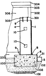
The foundation wall is arranged on a standard solid concrete footer 100,
which is buried in the earth 101 at a depth prescribed by local building codes
.
Besides being held by connectors (not shown) to structural panel 1, the steel
studs 7 are also tied together using steel tracks 9 at the top and the bottom
of the
studs. The rest of the structure supported by the foundation wall is depicted
as
being attached to the upper steel track using joist screws 305. The structure
300,
supported by the foundation wall, includes joist steel plate 301, rim joist
302, floor
joist 306, flooring 303, and wall sill plate 304. This is a standard building
arrangement, and any variety of such an arrangement can be used in conjunction
with the inventive foundation wall. Because of the strength of the subject
foundation wall, a wider variety of structures can be supported thereby, than
with
conventional masonry walls.
In order to affect a waterproof structure, it is preferable to place a
waterproof plastic membrane 6 (preferably polyethylene) under the wall
(galvanized steel track 9), and to bond that membrane to the outer PaxonTm
layer (2a) using a plastic weld 8. The plastic weld is easily effected at the
construction site, using either a thermal or ultrasonic welder and any number
of
different plastic welding rods to provide the weld material. On the interior
of the
steel studs 7, a concrete floor (as specified by local building codes) is
arranged to
overlap the interior portion of the foundation wall, as shown in Figure 2.
Normally, it would be desirable to place interior paneling on the steel studs.
However, this is not necessary to achieve the benefits of the present
invention.
While a single PaxonTm sheet can be used as the structural panel 1 on the
outer service of the studs 7 within the scope of the present invention, it is
preferable to use the structural panel 1 as depicted in Figure 1. This
arrangement
provides a much higher insulating level due to the Foamular (or other similar
insulating material) R values. Further, in the arrangement depicted in Figure
2, the
CA 02489927 2007-05-25
- 16
second Paxonrm sheet 2b on the interior side of structural panel 1 prevents
migration of moisture from inside the structure to the moisture-absorbing
insulating material 3. Since the permeability to water of the PaxonTM material
is
virtually zero (10,000 times less permeable to moisture than poured concrete),
the
center insulating layer 3 is protected on both sides. This protection is
rendered
complete by the plastic barrier 4 welded onto the periphery of the entire
panel.
Despite the strength of the structural panel sandwich of Figure 1, this is not
the primary axial load-bearing element in the foundation wall. Rather, the
structural steel frame work of 8-inch, 16-gauge steel studs, on 16-inch
centers, is
the primary support means for the wall system. As depicted in Figure 2, the
studs
are enclosed at both ends by 16-gauge, 8-inch steel tracks. The structural
wall
panel is connected through the studs using self-tapping, corrosion-resistant,
countersunk steel screws, at two-foot intervals along the height of the wall.
The
screw heads 91 are then sealed using plastic thermal welding.
It should be noted that while 8-inch steel studs are used in the embodiment
of Figure 2, other sizes of studs can be applied within the parameters of the
present
invention. For example, wood or plastic studs can be used. Each type has
certain
advantages and certain deficiencies when compared to steel studs. Accordingly,
the use of different materials will be dictated by the particular application
in which
an inventive wall system will be placed.
It should also be noted that a wide variance in the thicknesses in both the
PaxonTM and Foamular sheets of structural panel 1 are permitted within the
parameters of the present invention. For example, practical thicknesses of the
PaxonTM sheet ranges from 1/8 inch to 1 inch, for either the exterior (2a) or
the
interior (2b) sheets. The Foamular , insulating layer 3, is considered to have
a
practical range between 1/2 inch and 2 inches when applied to foundation
walls.
However, the Foamular could be virtually any thickness that is required, and
that
can be handled in the sandwich configuration of Figure 1.
Accordingly, there may be some applications, such as large scale
water-retention, that require much greater thicknesses of the PaxonTM panel
while
requiring lesser thicknesses of the Foamular . In some cases, the Foamular
may
not be needed at all. In other applications, only two layers (one of PaxonTM
CA 02489927 2004-12-22
-17-
and one of Foamular ) would be adequate. In other applications, the use of
only a
single PaxonTm panel would be necessary. Likewise, in some applications,
additional panels of the Paxon'"A can be applied to the overall wall
structure. For
example, an additional layer of PaxonT"' can be applied to the interior side
of the
steel studs 7 on the wall of Figure 2. This would prevent moisture from
migrating
from the interior of the building into the space between the studs. This could
be
particularly important if the spaces between the studs are filled with
moisture-
absorbing insulating material to increase the overall insulating value of the
wall in
R value greater than 14 (the maximum that can be expected from the example
containing 2 inches of Foamular and 7/8 inches of PaxonTm). Conceivably, the
steel studs 7 could have the structural panel sandwich of Figure 1 on both the
exterior and interior. This would result in a much stronger (although more
expensive) structure with much improved insulating capabilities. Even with
such
an arrangement, the overall weight of the wall system would be much lighter
than a
conventional masonry or poured concrete equivalent. As a result, large panels
could be fabricated at a factory, moved to the job site, and easily arranged
on the
footer t 00.
The strength of individual 3/8 inch and 1/2 inch PaxonTM panels can be
calculated. However, individual PaxonTm panels are seldom used in any
application in which they are expected to provide structural strength by
themselves. Rather the overall behavior of a wall system, such as that
depicted in
Figure 2, is important since the interaction of all of the elements in the
wall system,
and their effects on each other must be fully appreciated to determine how the
wall
system will behave under various types of stress.
An example for overall system characteristics is provided by the wall
system depicted in Figure 2 where studs are provided every 16 inches and
connecting screws are provided for every 2 feet of vertical dimension. The
wall is
assumed to be 10 feet in height and the weight of the wall itself is
negligible for
purposes of calculation.
One key aspect for considering the overall strength of the wall is thermal
expansion. As part of a consideration of thermal expansion, polymer-softening
temperatures should also be considered, in particular in the fitting of the
wall
CA 02489927 2004-12-22
-18-
system by drilling through holes for the connecting bolts or screws. When
handling the tracks and material, the drill bit may get hot due to friction
effects, so
that thermal effects must be considered. It is important that the flash point
or
ignition point of the Paxon rm material is not exceeded. It should be noted
that this
temperature would be considerably higher than the softening temperature. The
softening temperatures for the PaxonTM and Foamular are 254 degrees
Fahrenheit
and 150 degrees Fahrenheit, respectively. This should not be a problem since
if
the PaxonTm becomes warm during the drilling process, a slight amount of flow
or
expansion may occur. However, this would be advantageous, as it would help
seal
the screw into the panel. If the Foamular becomes too warm, it would shrink
back
a little bit and then immediately set again. Thus, structural panel 1 is
easily drilled
and mounted at a building site.
Warping, "creep," or "flow," caused by temperature extremes, is inhibited
by the steel-framing systems (studs 7 and steel tracking 9). The calculations
are
summarized below.
Despite the possible deflection due to a maximum possible force that could
occur on a 10 foot by 10 foot PaxonTm sheet, the capabilities of the
structural
panel 1 are such that the steel supports and the 3-layer design would serve to
stabilize and reinforce each of the layers, as well as compensating for any
creep or
flow. For example, for a 75 degree F temperature differential (a very large
temperature swing for most basement structures) a 1/2 inch thick 100 square
foot
panel would exert approximately 5,670 lb. However, the steel framing would
easily absorb this force.
The strength of the wall section of Figure 2 is such that for a 10 foot
length,
a single Paxon rm sheet could absorb 3.85 * 105 lb. Further, a Paxon"'M sheet
(1/2 inch by 1 foot by 3 foot) would have to be deflected 87 degrees before it
would snap or fail. Consequently, a structural panel such as that depicted in
Figure 1, having two Paxonlm sheets will be capable of withstanding four times
the
amount of moment capacity as a single sheet before bending. Used with the
steel
framework of studs 4 and tracks 9, the wall system is even stronger. For
example,
for a system similar to that depicted in Figure 2, the capacity of the steel
framing
without the PaxonTm sheet would be nominally 3 * 107 pounds per square inch.
CA 02489927 2004-12-22
-19-
The normal load of a basement wall is usually only 204 pounds per square inch
to
support itself. The difference in these two values is the capacity to support
an
overlying structure. Clearly the use of the steel frame with Paxon'rM panels
of
Figure 1 would provide foundation walls having the capacity to handle a far
wider
range of structures than is possible with conventional masonry or poured
concrete
foundation walls.
Another aspect is the strength of the Figure 2 wall against normal forces (as
opposed to shear forces caused by loads on top of the wall) caused by such
side
impacts as the weight of the earth against the wall, explosions, earthquakes,
water
pressure, and the like. To calculate normal strength of the wall, moment
calculations are made. A composite structural panel, such as that depicted in
Figure 1, can withstand a moment of 2 * 1010 lb. ft. Such a structural panel
requires 2400 times the moment necessary to bend a single PaxonTm panel. As a
consequence, studs 7 having 16 inch centers are more than adequate to support
such a wall panel from any normally-occurring forces. Because of this
strength,
and the flexibility of the steel studs, structures made using the foundation
wall
system depicted in Figure 2 have substantial earthquake and shockwave
resistance.
A crucial aspect of any foundation wall system is the drainage system
which takes water away from the wall and prevents water from accumulating at
the
foot of the wall (the source of most basement leaks). This is normally
accomplished with conventional ceramic drainage tiles located in a gravel bed
next
to the footer supporting the wall. Unfortunately, placement of such tiles is
time
consuming, and can be erratic if the installer is unskilled. Further, the
tiles can be
easily separated by normal shifting caused by freezing, water impact,
earthquakes,
or the like. Compacting the earth next to the files (whether by time or the
exertion
of substantial forces on the ground above the tile) can also dislodge the
tiles and
prevent proper drainage from the foot of the wall.
The solution included in the foundation wall system of the present
invention is an approximately square drainage track 5 that fits along the
footer 100,
which supports the foundation wall. The drain track is preferably made of
polyethylene. However, any similar material can be included within the scope
of
CA 02489927 2004-12-22
-20-
the present invention. Further, while an approximately square 3-inch by 3-
inch drain pipe has been used in tests, other sizes would also fall within the
scope
of the present invention. The bottom of the drainpipe has a plurality of
perforations 52, which accommodate rising ground water so that it can be
diverted
away from the foundation wall. The top surface of the drainpipe 5 has a sloped
surface 51 which prevents water accumulation near the top of the footer.
A 1/4 inch polyethylene membrane 6 is attached to drainpipe 5, and
configured to fit over the top of the footer and underneath the foundation
wall, as
depicted in Figures 2 and 3B. In the typical model of the inventive foundation
wall
system, membrane 6 is made up of Paxon FmBA 50/100 polyethylene. However,
other materials can be used. Preferably, the membrane 6 is configured for the
exact size and shape of the footer so that the footer can be entirely sealed
at the top
and part of the outer side surface. A polyethylene weld 8 (Figures 2 and 4) is
used
to seal the interface between the lower wall panel 1 and the top of membrane
6.
The weld can be made either at the building site or at a factory where
drainpipe 5
and membrane 6 are formed as part of large wall sections. The ends of
drainpipe 5
and membranes 6 at the edges of wall segments can be joined to adjacent wall
segments using standard plastic welding techniques.
Figure 4 depicts a detailed view of Figure 2, in particular the details of a
conduit system 10, which is arranged in pre-drilled holes in the studs 4. The
conduit system 1 0 is preferably square or rectangular in cross section,
containing
numerous sectionalized pathways 12 (as depicted in Figure 5). Conduit system
10
is preferably made of a sturdy plastic, which can be easily sealed at the
interfaces
of adjacent sections. Through the use of the compartments, specific types of
lines
can be limited to only certain portions of the conduit system. For example,
electrical lines could be in relatively large compartments while separated
from
cable lines, which would also be in separate large compartments. Telephone
lines
could be segregated into their own compartments, as would in-house data lines.
The compartments 12 of the conduit system 10 are also ideal for handling
optical
fibers, or any other exotic communications medium.
Any number of aligned pre-formed apertures in the steel studs 7 can be
used to accommodate the conduit system 10. Currently, multiple conduit
~ CA 02489927 2004-12-22
-21-
systems can be run through the same wall. It should be noted that compartments
in
the conduit system can be made large enough to accommodate plastic water lines
or air lines for hospital use. The conduits can be located virtually anywhere
along
the height of the system.
A major difficulty in conventional conduit systems resides at the corners of
the walls where heavy electrical cable often has to be pulled through a 90-
degree
turn. This is extremely difficult and tiresome for the installers. Often,
machine
assistance is necessary in order to pull the heavy electrical cable through
multiple
90-degree turns. This problem is virtually eliminated by the corner piece 11,
as
depicted in Figure 5. The corner piece has a 5-inch outer radius and a 3 -inch
inner
radius for a conduit cross-section of 2 inches by 2 inches. However, different
sizes
can be used while maintaining the concept of the present invention.
While the conduit system 10 can be made of a high-density polyethylene
material such as PaxonTM, there is no reason to use such a dense and durable
material in such a manner. Rather, virtually any type of plastic or similar
material
can be used to constitute the segments of the conduit system. The key aspect
regarding strength is that the corner units are capable of withstanding the
pressures
caused by pulling heavy electrical cable through thein. However, it should be
noted that many of the pressures generated as a result of conventional 90-
degree
tums have been eliniinated by the curved configuration of corner unit 11 of
the
present invention. As a result, a great deal of saving can probably be
achieved by
making the conduit system of a far lighter, less expensive material than is
required
by the rigors of conventional conduit-pulling. While a number of embodiments
have been disclosed by way of example, the present invention is not meant to
be
limited thereto. Accordingly, the present invention should be understood to
include any and all variations, modifications, permutations, adaptations,
derivations, and embodiments that would occur to an individual skilled in this
technology, once having been taught the invention by the present application.
Thus, the present invention should be limited only in accordance with the
following claims.