Note: Descriptions are shown in the official language in which they were submitted.
CA 02490032 2004-12-06
0067P44CA01
WO 03/103858 PCT/EP03/05908
Device Havin~an Operating and Functional Unit
CERTIFIED COPY
CA 02490032 2004-12-06
WO 03/103858 PCT/EP03/05908
2
Description
The invention relates to a device that is provided with a two-part
operating and functional unit which is designed as a pedestal- or table-
like unit. According to the invention, the device comprises a frame that
can be stationarily fixed in place and having two table-like supporting
plates, located next to one another, which are situated parallel to one
another in this frame. These table-like supporting plates are each
mounted separately and independent of one another so as to be movable
in three dimensions. At least one motorized drive is provided which sets
the table-like supporting plates in randomized, oscillating-pulsating
motion in at least one dimension, independent of one another. These
motions describe an elliptical or circular trajectory whose amplitudes
may be different. The particular frequency of these motions can be
modified.
The invention provides that each of the two table-like supporting plates
is positioned at both its end regions on forked mountings which are
movable in three dimensions and which accommodate bearings for both
ends of axle shafts of eccentric rollers for each of the two table-like
supporting plates. Limiting rollers are situated above the double-ended
eccentric rollers. These limiting rollers have an interspace "d" around the
circumference of each associated eccentric roller. The referenced
eccentric rollers have a cylindrical shape and eccentric axle shafts. Each
of the eccentric rollers is supported on one drive roller and one support
roller. The drive rollers cause the eccentric rollers to move in a rotary
motion, in the same or opposite direction, synchronously or
asynchronously. As a result of the eccentric bearing of the axis shafts in
CA 02490032 2004-12-06
WO 03/103858 PCT/EP03/05908
3
forked mountings which are movable in three dimensions, the axis shafts
are set in motion dependent on the rotational speed and describing
elliptical or circular trajectories.
These motions act on the supporting plates which are connected to the
forked mountings. The limiting rollers situated above the eccentric
rollers are responsible for limiting the oscillations of the eccentric rollers
when the latter, on account of their eccentric bearing, are lifted up from
their support position under the influence of centrifugal force.
The referenced drive rollers are mounted in side walls of the frame, and
are set in synchronous rotational motion in the same direction by at least
one motorized drive. In an alternative to this design, the drive rollers are
set in synchronous or asynchronous rotational motion in opposite
directions.
Further essential features of the invention lie in the fact that each of the
two table-like supporting plates is positioned at both its end regions on
the respective associated forked mountings. These mountings may also
have other designs that are not forked, and are provided with bearings for
the double-ended axle shafts of the eccentric rollers. Pads made of a
resilient material, or articulated joints, may be inserted between the
forked mountings and the table-like supporting plate so as to provide
capability for tilting in the transverse direction; however, a rigid
connection may also be provided so that there is no capability for tilting
in the transverse direction at the affected site.
CA 02490032 2004-12-06
WO 03/103858 PCT/EP03105908
4
An alternative design also provides that on each of the two table-like
supporting plates longitudinal tilting axles extending in the x axis are
present on which the cover plates are tiltably linked by connecting
pieces. Instead of these longitudinal axles, longitudinal hinges may also
be provided by which the supporting plates may be tiltably connected.
Essential features of the invention lie in the fact that the table-like
supporting plates are mounted so as to be movable in three dimensions.
To drive the device, it is sufficient to have at least one drive motor which
sets one or more components of the unit in oscillatory motion in at least
one dimension. The frequency of these oscillatory motions may be
modified within certain limits. Furthermore, the amplitudes of the
oscillatory motion may also be modified within certain limits.
The device may be used for various purposes and applications in which it
is important for objects, materials, or substrates to be acted on by
rhythmical or arrhythmical mechanical impacts or vibrations. Thus, for
large-particle bulk materials, separating or sorting processes can be
initiated or performed, or for fine-particle or powdered bulk materials
mixing or homogenizing procedures can be carned out. When the two-
sided supporting plates or the cover plates joined to same are connected
to one another by a rigid or resilient element by means of articulated
connections, these impactive or oscillatory effects can produce a
sequence of pulsating and divergent, irregular or randomized motions for
these elements that are independent of one another.
CA 02490032 2004-12-06
WO 03/103858 PCT/EP03/05908
5
The device may also be used as training/fitness equipment, or as a
medical therapy apparatus for persons or animals, in particular to
increase their coordination abilities and/or to stimulate certain muscles.
One interesting area of application in particular is the loosening and
relaxation of the musculature of high-performance athletes, especially
ski jumpers and downhill racers. A further interesting area of application
is the stimulation of the muscles of persons with Parkinson's disease. It
has been shown that symptoms such as stiffness or tremors may be
beneficially affected.
It has proven to be particularly advantageous for the table-like
supporting plates to have an amplitude of approximately 3 mm at a
frequency of 1 - 20 Hz, preferably 4 - 6 Hz.
The device may additionally be used to address various problems in
different fields. When objects, materials, or substrates are subjected to
the referenced rhythmical or arrhythmical, impactive or oscillatory
effects, it is possible to produce the various changes described above,
such as effects on the crystalline structures of solid materials.
According to further features, the device may be provided with at least
one fastening device for the detachable, impact- and vibration-free
connection of a receptacle for a vessel or mounting. The attachable
vessel may be used for receiving free-flowing material provided for
processing; by use of the mounting, solids or similar materials for
CA 02490032 2004-12-06
WO 03/103858 PCTJEP03/05908
6
processing may be connected to the device in an impact- and vibration-
free manner. The fastening device may comprise a receptacle that
includes a shoe, mounted on the supporting plate or cover plate, which is
used to securely place or insert the object to be fastened. The fastening
device may also include belts and/or straps with buckles, or it may be
provided with support mountings with adjustable clips.
These fastening devices, in particular belts and/or straps with buckles,
may be used to secure human or animal limbs. A device with fastening
devices having such a design is particularly suited as training/fitness
equipment or a therapy device of the type described above.
In one particular embodiment of this device having the latter referenced
type of design, according to the invention seating and/or supporting
capability is provided to provide the particular persons with stability
while the device is operating.
Exemplary embodiments of the invention are schematically illustrated in
the drawings listed below, and are described in greater detail below.
Figure 1 shows a side view of the device without a cover;
Figure 2 shows a partial section through the mechanical moving part
of one of the two halves of the device;
Figure 3 shows a partial side view with partial sections;
CA 02490032 2004-12-06
WO 03/103858 PCT/EP03/05908
7
Figure 4 shows a cross section with both halves of the device;
Figure 5 shows a cross section with both halves of the device in an
alternative design;
Figure 6 shows a cross section with both halves of the device in a
further alternative design;
Figure 7 shows a partial side view with partial sections on the
supporting plate and the cover plate;
Figure 8 shows a partial side view with partial sections on the
supporting plate and the cover plate according to Figure 7;
Figure 9 shows a partial side view with partial sections on the
supporting plate and the cover plate according to Figure 8;
Figure 10 shows a partial side view with partial sections on the
supporting plate and the cover plate according to Figure 8,
in an alternative design;
Figure 11 a) through c) shows three schematic illustrations of the
possible motions of the device;
Figure 12 shows an alternative device according to Figure 4;
Figure 13 shows a side view of the device without a cover, in an
alternative design; and
Figure 14 shows an illustration of the device with a complete cover.
CA 02490032 2004-12-06
WO 03/103858 PCT/EP03/05908
8
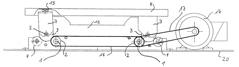
The device is illustrated in the side view without a cover in Figure 1. The
device has two drive shafts 1 running transverse to the longitudinal
direction which are separated from one another in their longitudinal
direction, and which are synchronously driven in the same rotational
direction by a motorized drive 16/17 comprising a drive motor 16 and
drive belts 17. Each of the two drive shafts 1 running in the transverse
direction bears a drive roller 2 on each of its two ends. The two drive
shafts 1 are synchronously connected to one another in the same
rotational direction by a toothed belt connection 15.
The right side of the system depicted in Figure 1 is illustrated in Figure
2. The corresponding side of the drive shaft 1 and the drive roller 2
situated thereon can also be seen. The eccentric roller 3, which is
supported so as to roll out on the drive roller 2 as well as a support roller
4, is also evident in Figure 2. It can be seen in Figure 2 that the eccentric
roller 3 has an eccentric axle shaft 5. As a result of the rotation of the
eccentric roller 3, with each revolution the axle shaft 5 of the eccentric
roller performs a motion, in at least the magnitude of the eccentricity,
describing an oscillatory, ellipsoidal, or circular path. This motion,
referred to below as ellipsoidal motion, is composed of a simultaneous
vertical and horizontal motion which is transmitted to the bearings 6 of
the axle shaft 5. This bearing 6 is installed in a forked mounting 7. The
forked mounting 7 thereby likewise experiences a repetitive oscillating
motion, referred to as ellipsoidal motion, which is directed vertically and
horizontally. Reference number 12 denotes a side wall which is rigidly
mounted and securely joined to the frame 20.
CA 02490032 2004-12-06
WO 031103858 PCT/EP03/05908
9
The bearings 9 for bearing the axle journals 10 for the support roller 4
and the limiting roller 11 are situated in this side wall 12.
Duration rotation, due to the centrifugal forces which occur the eccentric
roller 3 may lift up from the drive roller 2 and the support roller 4 on
which the eccentric roller 3 rests. This lifting is not detrimental, and in
fact is even desirable under certain conditions. In this manner the
uniformity of the rotational motions of the eccentric roller 3 is
interrupted for fractions of a second, thereby irregularly modifying the
rotational speed of the eccentric roller, as desired, as the result of the
slippage created. The limiting roller 11 is responsible for imposing an
upper limit for the vertical lift displacement and lifting of the eccentric
roller 3. An interspace "d" is maintained between the eccentric roller 3
and the limiting roller 11, as shown in Figure 2. This interspace "d" also
limits the maximum degree of lifting of the eccentric roller 3. The non-
uniformity of the rotational motion thus produced is also transmitted to
the forked mounting 7, and as the result of the mass inertia or interaction
of impacts and oscillations, is transmitted to objects, persons, animals,
materials, or substrates situated on the supporting plate 8 or secured to
same. These effects are facilitated by the fact that the supporting plate 8
is movable or tiltable in the transverse direction as well, since the
eccentric roller 3 permits sufficient clearance due to its distance "d" from
the limiting roller 11.
Figure 3 shows the device in the side view. 'The right side corresponds in
all essential features to the illustration in Figure 2. The illustration on
the
left side corresponds to the left side of Figure 1. The referenced right
CA 02490032 2004-12-06
WO 03/103858 PCT/EP03/05908
10
side of the illustration in Figure 3 shows the same features and elements
of Figure 2: the drive shaft is designated by reference number l, and the
drive roller is designated by 2. Here as well, the eccentric roller 3 is
supported on the drive roller 2 and the support roller 4. Here the
eccentric roller 3 is also borne by its axle shaft 5 in the forked mounting
7, which is designed to move in three dimensions. The interspace "d" in
Figure 3 is intentional; it is between 1 and 50 mm, and as mentioned
above makes it possible for the eccentric roller to lift up and allows the
impacts and oscillations of the eccentric roller 3, depending on the
particular instantaneous distance "d," to be transmitted to the forked
mounting 7 with varying intensities and in different time intervals (and
thus in variable frequencies), as intended.
As can be seen from the illustration on the left side of Figure 3, the
forked mounting 7 which is movable in three dimensions bears on its
upper flattened end at least one pad 13 made of an elastic, resilient
material. The supporting plate 8 is supported on this pad 13, and as a
result of this mounting is tiltable within certain limits on account of the
additional degree of freedom thus provided in the direction transverse to
the longitudinal extension of the device. Furthermore, the pads) 13 are
used to absorb the longitudinal displacement that is transmitted from the
forked mounting 7 to the supporting plate 8. An articulated joint may
also be used instead of the pad 13.
As an alternative to the embodiment described above, the comparative
design of the right illustration in Figure 3 is not provided with a pad 13.
Instead, the supporting plate 8 connected to the forked mounting 7 which
is movable in three dimensions is not able to tilt in the transverse
CA 02490032 2004-12-06
WO 03/103858 PCT/EP03/05908
11
direction at this location, since the supporting plate 8 (see Figure 3) is
rigidly connected to the forked mounting 7 by threaded connections 23.
Nevertheless, a tilting motion of the supporting plate 8, which is screwed
to the forked mounting 7, in the transverse direction is very well possible
and is intended, since the eccentric roller 3, as described above, permits a
corresponding degree of freedom due to its distance "d" from the
limiting roller 11.
It is within the scope of the invention to connect these supporting plates
8 at both their end regions to the forked mountings 7 by means of at least
one resilient pad 13 or at least one articulated joint 13.
Figure 3 also shows a design on the right side that is a mirror image of
all the features of the design on the left side. The mirror-image
corresponding features are therefore provided with matching reference
numbers. Here as well, the drive shaft is designated by reference number
l, and the drive roller is designated by 2. The eccentric roller 3 is also
supported here on the drive roller 2 and the support roller 4. Here as
well, the limiting roller 11 is situated above the eccentric roller 3 while
maintaining the distance "d."
Furthermore, the motorized drive for the device is partially visible in
Figure 3. A drive motor, not shown, drives the drive shaft 1 by means of
a toothed belt connection 17. The respective right and left sides of the
drive rollers 2 are each connected by the toothed belt 15, and are thus
driven synchronously in the same direction. The frame on which the side
wall 12 is fastened is designated by reference number 20 in Figure 3.
One alternative, not shown, involves driving the drive rollers 2 in the
CA 02490032 2004-12-06
WO 03/103858 PCT/EP03/05908
12
same direction but asynchronously, or synchronously in opposite
directions, or asynchronously in opposite directions, using one or more
motors.
Figure 4 shows a cross section through the device. The common drive
shaft 1 for both sectional designs, which are situated adjacent and
parallel to one another and which are fastened to the frame 20 one
behind the other in the longitudinal direction of the device, can be seen
here. A drive roller 2 rests on each of the drive shafts 1 of the two
adjacently situated sectional designs. The eccentric rollers 3 are
supported on this drive roller and on support rollers 4, not shown (see
Figures 1 through 3). On each end these eccentric rollers have eccentric
axle shafts 5 which are held in the forked mountings 7 in the bearings 6.
The impacts and oscillations of the axle shafts 5 are thus transmitted to
these forked mountings 7 which are movable in three dimensions, and set
the latter in ellipsoidal motion. The limiting rollers 11 located thereabove
are borne by their axle journals 10 in the bearings 9, in the side walls 12.
Tilting motions of the supporting plates 8 are also possible, since the
eccentric rollers 3 have an additional degree of freedom because of their
distance "d" from the limiting rollers 11. The supporting plates 8 are
fastened to the forked mountings by threaded connections 23, and the
tiltable bearing systems of the cover plates 14 are centrally located on
these supporting plates. The cover plates are supported about the
longitudinal "x" axes in the rocker bearings 24, with a limited ability to
tilt. This results in an additional degree of freedom for the cover plates
14, which are movable through a limited tilt angle in the transverse
direction.
A variation of the design according to Figure 4 is illustrated in Figure 5.
In a design that otherwise is identical to Figure 4, here the supporting
CA 02490032 2004-12-06
WO 03/103858 PCT/EP03/05908
13
plates 8 are not rigidly connected to the forked mountings 7, but instead
are connected to the mountings 7 via the pads 13 or articulated joints.
The latter are used to absorb the longitudinal displacement that is
transmitted from the forked mounting 7 to the supporting plate 8.
An additional alternative design can be seen in Figure 6. Here, the
supporting plates 8 are provided on each end with U-shaped longitudinal
tracks 27 whose U openings point inward, and in which rollers or roller
bearings 28 are guided which are connected by bearing journals 29 to the
forked mountings 7. This track connection is used to absorb the
longitudinal displacement that is transmitted from the forked mounting 7
to the supporting plate 8.
As a result of these overall device features, the device is designed so that
the two adjacently situated supporting plates 8 can perform limited
ellipsoidal motions in the vertical and horizontal directions, and the
cover plates 14 connected to the supporting plates 8 likewise can
perform ellipsoidal motions in the vertical and horizontal directions as
well as tilting motions about longitudinal "x" axes, and that, independent
of one another, the supporting plates and cover plates are set in
impactive or oscillatory ellipsoidal motions of different frequencies. 'The
ellipsoidal motions may be different in form. Also, the corresponding
degree of freedom is additionally tiltable by [distance] "d" from the
eccentric roller 3 to the limiting roller 11 [apparent omission in source
document].
Figure 7 shows the alternative designs, illustrated in Figures 5 and 6, of
the connection between one of the cover plates 14 to its associated
CA 02490032 2004-12-06
WO 03/103858 PCT/EP03/05908
14
supporting plate 8 in a side perspective view. The cover plates 14 are
tiltable about the x axis as a result of the rocker bearing 24 and the
rocker holder 30. The rocker bearings are joined to the supporting plate 8
by screws 31. The cover plates 14 are thus movable within narrow limits
in the transverse direction, as indicated by the dashed lines.
Figure 8 shows an alternative design with respect to Figure 7. Here, the
cover plates 14 are able to move in three dimensions, held in the central
surface area of the supporting plates 8 by screw bolts 35 on an elastic
intermediate bearing disk 36. Tilting motions by the cover plates 14 in
both the transverse and longitudinal directions are thus made possible.
To limit these tilting motions by the cover plates 14 in both directions,
sickle-shaped slits 37 are incorporated therein which are guided in
stationary positioning bolts 38 and limit the range of motion of the cover
plates. As a result of this mounting of the attachment in these stationary
positioning bolts 38, the cover plates 14 are able to swivel about the
positioning bolts and also slightly tilt in the longitudinal and transverse
directions.
Figures 9 and 10 show the designs according to Figure 8, using
additional devices which enable the motions of the cover plates 14 on the
supporting plates 8 to be partially or totally limited. In Figure 9 a slider
bar having a horizontal slot is designated by reference number 40. The
slider bar 40 can be pushed in the longitudinal direction until all or part
of a projection 42 from the cover plate 14 is taken inside the slot 41.
When the slider bar 40 is pushed all the way, the projection 42 is fixed
therein, so that the cover plate 14 is fixed as well and can no longer
move. If the motion of the cover plate 14 is to be only limited, the slider
CA 02490032 2004-12-06
WO 03/103858 PCT/EP03/05908
15
bar 40 is pushed only part of the way, and is held in this position by the
adjusting screw 43.
A variant of this design of the total or partial limitation of motion of the
cover plate 14 on the supporting plate 8 can be seen in Figure 10. Here,
two sliding pieces 44, 45 with rising, ramp-like inclined surfaces 46, 47
are provided by which the particular cover plate 14 can be totally or
partially fixed in place by pushing the sliding piece forward.
Figure 11 shows a schematic partial side view of the device according to
one of Figures 1 through 3, illustrating three different positions a)
through c) of the forked mountings 7 resulting from the eccentricity of
the axle shafts 5 or eccentric rollers 3. The various ellipsoidal motions of
[the forked motions ofJ [sic'] the forked mountings 7, and thus of the
supporting plates connected thereto, can be seen from these positions.
In Figure 12 a design according to Figure 4 can be seen, in which the
eccentric roller 3 has a shell surface that is convex instead of cylindrical.
The degree of convexity may be between 1.00 mm and 10.00 mm. In a
further variant, the limiting roller 11 in addition to the eccentric roller 3
may also have a convex shell surface. These convex shell surfaces enable
the forked mountings 7 to be influenced with respect to even greater
tiltability in the transverse direction.
Figure 13 illustrates a variant of Figure 1. Here, the eccentric roller 3 is
~ Translator's note: bracketed text is superfluous in source document.
CA 02490032 2004-12-06
WO 03/103858 PCT/EP03/05908
16
driven only indirectly by a drive roller 2, since the eccentric roller 3 lies
on a conveyor belt 21 that is driven by a drive roller 2. Because the
eccentric roller 3 lies directly on the conveyor belt 21, the eccentric
roller 3 is driven by this conveyor belt. This design simplifies the drive,
since in each case a special drive roller is spared. The drive train is
transmitted from the drive motor 16 and the drive belt 17, over a drive
roller 2 by means of a conveyor belt 21, directly to the eccentric rollers 3
lying on the conveyor belt 21.
Lastly, Figure 14 shows the overall device with the two cover areas 14
which, situated next to one another in a cutout 48 in the top side 49 of
the complete covering 50, may be externally acted on or loaded by
objects or the like.
As a result of the independent motions of asynchronous, randomized
ellipsoidal impacts and oscillations of the inventive device, a container
or (human, animal, or other) body connected to the two supporting plates
8 or cover plates 14 may be set in extremely effective vibration.
CA 02490032 2004-12-06
WO 03/103858 PCT/EP03/05908
17
List of reference numbers
I Drive shaft
2 Drive roller
3 Eccentric roller
4 Support roller
5 Axle shaft
6 Bearing for axle
shaft
7 Forked mounting
8 Supporting plate
9 Bearing for axle
journal
10 Axle journal
11 Limiting roller
12 Side wall
13 Pad
14 Cover plates
15 Toothed belt connection
16 Drive motor
17 Drive belt
20 Frame
21 Conveyor belt
23 Threaded connection
24 Rocker bearing
27 Longitudinal tracks
28 Roller bearing
29 Bearing journal
30 Rocker holder
31 Screws
32 Screw connections
33 Bearing blocks
35 Screw bolts
CA 02490032 2004-12-06
WO 03/103858 PCT/EP03/05908
18
36 Intermediate bearing
disk
37 Sickle-shaped slits
38 Positioning bolt
40 Slider bar
41 Slot (in slider bar)
42 Projection from cover
plate
43 Adjusting screw
44 Sliding piece I
45 Sliding piece II
46 Inclined surface
I
47 Inclined surface
II
48 Cutout
49 Top side of covering
50 Complete covering