Note: Descriptions are shown in the official language in which they were submitted.
CA 02490066 2004-12-17
WO 03/105940 PCT/US03/18728
PLUGGED TIP DELIVERY TUBE FOR MARKER PLACEMENT
FIELD OF THE INVENTION
[0001] The invention is directed generally to devices and methods for
delivering
markers to a desired location within a patient's body. In particular, the
invention is
directed to devices, assemblies, and methods configured to retain a biological
marker within a delivery device before delivery of the marker to a desired
intracorporeal location.
BACKGROUND OF THE INVENTION
[0002] In diagnosing and treating certain medical conditions, it is often
desirable
to mark a suspicious body site for the subsequent taking of a biopsy, delivery
of
medicine, radiation, or other treatment, to mark a location from which a
biopsy was
taken, or at which some other procedure was performed. As is known, obtaining
a
tissue sample by biopsy and the subsequent examination are typically employed
in
the diagnosis of cancers and other malignant tumors, or to confirm that a
suspected
lesion or tumor is not malignant. The information obtained from these
diagnostic
tests and/or examinations is frequently used to devise a therapeutic plan for
the
appropriate surgical procedure or other course of treatment.
[0003] In many instances, the suspicious tissue to be sampled is located in a
subcutaneous site, such as inside a human breast. To minimize surgical
intrusion
into patient's body, it is often desirable to insert a small instrument, such
as a biopsy
needle, into the body for extracting the biopsy specimen while imaging the
procedure using fluoroscopy, ultrasonic imaging, x-rays, magnetic resonance
imaging (MRI) or any other suitable form of imaging technique. Examination of
tissue samples taken by biopsy is of particular significance in the diagnosis
and
1
CA 02490066 2004-12-17
WO 03/105940 PCT/US03/18728
treatment of breast cancer. In the ensuing discussion, the biopsy and
treatment site
described will generally be the human breast, although the invention is
suitable for
marking biopsy sites in other parts of the human and other mammalian body as
well.
[0004] Periodic physical examination of the breasts and mammography are
important for early detection of potentially cancerous lesions. In
mammography, the
breast is compressed between two plates while specialized x-ray images are
taken.
If an abnormal mass in the breast is found by physical examination or
mammography, ultrasound may be used to determine whether the mass is a solid
tumor or a fluid-filled cyst. Solid masses are usually subjected to some type
of
tissue biopsy to determine if the mass is cancerous.
[0005] If a solid mass or lesion is large enough to be palpable, a tissue
specimen
can be removed from the mass by a variety of techniques, including but not
limited
to open surgical biopsy, a technique known as Fine Needle Aspiration Biopsy
(FNAB) and instruments characterized as "vacuum assisted large core biopsy
devices".
[0006] If a solid mass of the breast is small and non-palpable (e.g., the type
typically discovered through mammography), a biopsy procedure known as
stereotactic needle biopsy may be used. In performing a stereotactic needle
biopsy
of a breast, the patient lies on a special biopsy table with her breast
compressed
between the plates of a mammography apparatus and two separate x-rays or
digital
video views are taken from two different points of view. A computer calculates
the
exact position of the lesion as well as depth of the lesion within the breast.
Thereafter, a mechanical stereotactic apparatus is programmed with the
coordinates
and depth information calculated by the computer, and such apparatus is used
to
precisely advance the biopsy needle into the small lesion. Depending on the
type of
2
CA 02490066 2004-12-17
WO 03/105940 PCT/US03/18728
biopsy needle(s) used, this stereotactic technique may be used to obtain
cytologic
specimens, e.g., obtained through FNAB or it may be used to obtain histologic
specimens e.g., obtained through coring needle biopsy. Usually at least five
separate biopsy specimens are obtained from locations around the small lesion
as
well as one from the center of the lesion.
[0007] The available treatment options for cancerous lesions of the breast
include various degrees of mastectomy or lumpectomy and radiation therapy, as
well
as chemotherapy and combinations of these treatments. However,
radiographically
visible tissue features, originally observed in a mammogram, may be removed,
altered or obscured by the biopsy procedure, and may heal or otherwise become
altered following the biopsy. In order for the surgeon or radiation oncologist
to direct
surgical or radiation treatment to the precise location of the breast lesion
several
days or weeks after the biopsy procedure was performed, it is desirable that a
biopsy site marker be placed in or on the patient's body to serve as a
landmark for
subsequent location of the lesion site. A biopsy site marker may be a
permanent
marker (e.g., a metal marker visible under X-ray examination), or a temporary
marker (e.g., a bioresorbable marker detectable with ultrasound). While
current
radiographic type markers may persist at the biopsy site, an additional
mammography generally must be performed at the time of follow up treatment or
surgery in order to locate the site of the previous surgery or biopsy. In
addition, once
the site of the previous procedure is located using mammography, the site must
usually be marked with a location wire which has a hook on the end which is
advanced into site of the previous procedure. The hook is meant to fix the tip
of the
location wire with respect to the site of the previous procedure so that the
patient
can then be removed from the confinement of the mammography apparatus and the
3
CA 02490066 2004-12-17
WO 03/105940 PCT/US03/18728
follow-up procedure performed. However, as the patient is removed from the
mammography apparatus, or otherwise transported the position of the location
wire
can change or shift in relation to the site of the previous procedure. This,
in turn,
can result in follow-up treatments being misdirected to an undesired portion
of the
patient's tissue.
[0008] As an alternative or adjunct to radiographic imaging, ultrasonic
imaging
and visualization techniques (herein abbreviated as "USI") can be used to
image the
tissue of interest at the site of interest during a surgical or biopsy
procedure or
follow-up procedure. USI is capable of providing precise location and imaging
of
suspicious tissue, surrounding tissue and biopsy instruments within the
patient's
body during a procedure. Such imaging facilitates accurate and controllable
removal
or sampling of the suspicious tissue so as to minimize trauma to surrounding
healthy
tissue.
[0009] For example, during a breast biopsy procedure, the biopsy device is
often
imaged with USI while the device is being inserted into the patient's breast
and
activated to remove a sample of suspicious breast tissue. As USI is often used
to
image tissue during follow-up treatment, it may be desirable to have a marker,
similar to the radiographic markers discussed above, which can be placed in a
patient's body at the site of a surgical procedure and which are visible using
USI.
Such a marker enables a follow-up procedure to be performed without the need
for
traditional radiographic mammography imaging which, as discussed above, can be
subject to inaccuracies as a result of shifting of the location wire as well
as being
tedious and uncomfortable for the patient.
[0010] Placement of a marker or multiple markers at a location within a
patient's
body requires delivery devices capable of holding markers within the device
until the
4
CA 02490066 2010-12-10
device is properly situated within a breast or other body location.
Accordingly,
devices and methods for retaining markers within a marker delivery device
while
allowing their expulsion from the devices at desired intracorporeal locations
are
desired.
SUMMARY OF THE INVENTION
[0011] The invention provides devices and systems for delivery of markers
to a site within the patient's body. Delivery systems embodying features of
the
invention include a marker delivery tube with a removable plug. Plugs
embodying
features of the invention are held within an orifice at the tip of the
delivery tube,
retaining markers within the delivery tube, until it is desired that the
markers be
ejected. The plug may then be ejected or removed from the orifice, allowing
the
delivery of the markers to a desired site within a patient's body. Plugs and
delivery tubes embodying features of the invention may have retaining
features,
such as recesses or protuberances, configured to releasably retain a plug
within
a delivery tube until ejection of the plug from the delivery tube is desired.
The
retaining features are typically complementary pairs, such as a plug
protuberance
configured to fit into a recess in a delivery tube.
[0011a] According to one aspect of the present invention, there is provided
an intracorporeal marker delivery device for delivering a plurality of markers
to a
desired site within a patient's body from which tissue has been removed. The
intracorporeal delivery device comprises a delivery tube which has a tapered,
tissue penetrating distal tip, an inclined discharge orifice in the tapered
distal tip
and an inner bore extending to the inclined discharge orifice. The marker
delivery
device further comprises a plurality of remotely detectable markers which are
formed at least in part of bioresorbable material, which partially occlude the
inner
bore and are slidably disposed within the inner bore and at least one of which
has
a permanent radiopaque element disposed therein. The marker delivery device
further comprises an expandable plug, which is formed at least in part of
bioresorbable material, which is releasably secured within the inner bore of
the
delivery tube distal to the plurality of remotely detectable markers within
the inner
bore, and which is configured to retain the plurality of remotely detectable
markers within the inner bore, and which has an inclined exposed surface,
which
5
CA 02490066 2010-09-30
is configured to partially occlude the inclined discharge orifice, and which
allows
passage of at least one remotely detectable marker out of the inclined
discharge
orifice when the expandable plug is released from the inner bore. The marker
delivery device comprises a plunger slidably disposed within the inner bore
proximal to the plurality of remotely detectable markers.
[0011 b] According to another aspect of the present invention, there is
provided a marker delivery system comprising a delivery tube which has a
distal
tip with a discharge orifice, and an inner bore extending in the delivery tube
to the
discharge orifice in the distal tip, a plurality of remotely detectable
markers which
partially occlude the inner bore and are slidably disposed within the inner
bore, a
movable plunger disposed within the inner bore, and a plug releasably secured
within the discharge orifice within the distal tip to only partially occlude
the
discharge orifice, the plug is formed from a marking material.
[0011c] According to still another aspect of the present invention, there is
provided an intracorporeal marker delivery device comprising a delivery tube
which has a distal tip, a discharge orifice and an inner bore extending to the
discharge orifice, at least one remotely detectable marker which is slidably
disposed within the inner bore, and a plug comprising a marker body which is
releasably secured within the inner bore distal to the at least one remotely
detectable marker, the marker body is configured to retain the at least one
remotely detectable marker when secured within the inner bore, the marker body
has an inclined exposed surface which is configured to at least partially
occlude
the discharge orifice at the distal tip, and the delivery tube allowing
passage of
the at least one remotely detectable marker out of the discharge orifice when
the
marker body is released from the inner bore.
[0012] Assemblies embodying features of the invention include marker
delivery devices having a delivery tube with an orifice at its distal tip, an
inner
bore leading to an orifice, and at least one marker (preferably more than one)
within the bore of the delivery tube. A plug is disposed at least in part
within the
bore and orifice to prevent markers from prematurely passing through the
orifice
and to prevent tissue from entering the bore when the delivery tube is
advanced
5a
CA 02490066 2010-09-30
through tissue. The plug may itself serve as a marker, and may be the sole
marker, although typically the
5b
CA 02490066 2004-12-17
WO 03/105940 PCT/US03/18728
delivery tube contains a plug and at least one other marker. The plug is
releasably
secured within or adjacent to the orifice in order to retain a marker within
the delivery
tube bore proximate thereto but to allow passage of the marker out of the
orifice
when the plug is ejected from the orifice. The plug may partially or
completely
occlude the orifice, and is configured to retain the marker within the
delivery tube
before the marker is to be placed at a desired location within a patient's
body, and to
allow the marker to pass out of the orifice when delivery of the marker is
desired. A
movable plunger may be slidably disposed within the tube from an initial
position
accommodating the marker or markers and the plug within the tube, to a
delivery
position to push a marker against the plug to push the plug out of the orifice
and to
then eject one or more markers through the orifice.
[0013] The plug is preferably configured to be releasably retained within the
delivery tube, and may be aligned in a preferred orientation within the
delivery tube,
to properly orient an inclined face within the orifice. A plug may be
configured to fit
tightly within a part of the bore of a delivery device so as to be retained by
pressure;
may have a portion configured to contact a slot, hole, notch, ridge, tab, lip,
or other
feature of a delivery tube; may be configured to be retained by a tab; may
include an
internal retention element, such as a coil, a spring, a clip, a loop, an arch,
or a
resilient core, that is configured to press an outer portion of a plug against
a delivery
tube wall or to contact a retaining feature such as a tab, slot, notch or
hole; may be
pressed against at least part of the bore of a delivery tube by an external
retention
element such as a pin, wedge, clip, spring, coil or other element applied to a
plug; or
by otherwise engaging a portion of a delivery tube effective to be releasably
retained
within a delivery tube.
6
CA 02490066 2004-12-17
WO 03/105940 PCT/US03/18728
[0014] The plug is preferably biocompatible, and may itself be a marker that
is
detectable within a patient's body visually, tactilely, by imaging (including
ultrasound,
radiographic, magnetic resonance, or other form of imaging), or is otherwise
detectable. A plug may be a bio-resorbable temporary marker made up of bio-
resorbable materials, or may be a permanent marker including non-bio-
resorbable
materials as well. A plug may also include bio-active materials (e.g.,
hemostatic
materials, anesthetic materials, absorbent materials, antibiotic materials,
antifungal
materials, antiviral materials, chemotherapeutic materials, radioactive
materials, and
other pharmaceutical materials) as well as biologically inert materials.
[0015] Systems and devices embodying features of the invention may have
markings or indicators to aid in placement of the delivery tube in a desired
location.
In addition, methods of using systems and devices embodying features of the
invention include guiding the insertion of the delivery tube with the aid of
an imaging
device, such as an ultrasound imaging device, an x-ray imaging device, and a
magnetic resonance imaging device, which may be used to image the plug, a
marker retained within the delivery device, a portion of the delivery device,
or
combinations of these.
[0016] The invention provides the advantages of securely retaining markers
within a marker delivery device, improving accuracy and avoiding errors in of
placement of markers at desired locations within a patient's body, preventing
ingress
of tissue into the distal tip of the device when it is advanced through
tissue, and
guiding the device by use of an imaging device. These and other advantages of
the
invention will become more apparent from the following description when taken
in
conjunction with the accompanying drawings.
7
CA 02490066 2004-12-17
WO 03/105940 PCT/US03/18728
BRIEF DESCRIPTION OF THE DRAWINGS
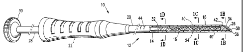
[0017] Figure 1A is a partly cut-away perspective view of a marker delivery
assembly embodying features of the invention showing several markers within a
marker delivery device and a plug embodying features of the invention
occluding the
tip of the delivery device.
[0018] Figure 1 B is a transverse cross-sectional view of the marker delivery
assembly of Figure 1 A taken at line 1 B-1 B.
[0019] Figure 1C is a transverse cross-sectional view of the marker delivery
assembly of Figure 1 A taken at line 1 C-1 C.
[0020] Figure 1D is a transverse cross-sectional view of the marker delivery
assembly of Figure IA taken at line ID-11D.
[0021] Figures 2A-C and 2D -2G are longitudinal cross-sectional views of a
delivery tube distal portion embodying features of the invention configured to
retain a
plug, containing markers and a plug embodying features of the invention.
[0022] Figure 2D is a transverse cross-sectional view of the delivery tube
distal
portion and plug shown in Figure 2C.
[0023] Figure 3A is a longitudinal cross-sectional view of a compressible plug
embodying features of the invention disposed outside a distal portion of a
delivery
tube.
[0024] Figure 3B is a longitudinal cross-sectional view of the compressible
plug of
Figure 3A embodying disposed within the distal portion of the delivery tube.
[0025] Figure 3C is a longitudinal cross-sectional view of an alternative
embodiment of a compressible plug.
8
CA 02490066 2004-12-17
WO 03/105940 PCT/US03/18728
[0026] Figure 3D is a longitudinal cross-section of a plug containing an
internal
retention element configured to press against the wall of a delivery tube.
[0027] Figure 4A is a longitudinal cross-sectional view of a plug embodying
features of the invention disposed outside a distal portion of a delivery
tube.
[0028] Figure 4B is a longitudinal cross-sectional view of an external
retention
element and of a plug embodying features of the invention disposed within a
distal
portion of a delivery tube.
[0029] Figure 4C is a longitudinal cross-sectional view of the external
retention
element inserted into the plug of Figure 4B embodying disposed within the
distal
portion of the delivery tube.
[0030] Figure 4D is a perspective view of a sharp tip of a delivery tube
distal
portion embodying features of the invention having slits forming a tab
configured to
retain and align a plug.
[0031] Figure 4E is a longitudinal cross-section of a delivery tube distal
portion
embodying features of the invention having a tab configured to retain a plug,
and
containing a plug configured to be retained and aligned by a tab.
[0032] Figure 4F is a longitudinal cross-section of a delivery tube distal
portion
embodying features of the invention having a tab configured to retain and
align a
plug, and containing a plug configured to be retained by a tab.
[0033] Figures 5A-5H are alternating plan and elevation views of distal
portions of
delivery tubes of marker delivery devices embodying features of the invention
configured to retain a plug by having holes or slots through the tube wall.
[0034] Figure 6 is a partially cut away, perspective view of a human breast
having
a lesion from which a biopsy specimen has been removed, and showing a guide
cannula and a marker delivery assembly embodying features of the invention
9
CA 02490066 2004-12-17
WO 03/105940 PCT/US03/18728
inserted into the breast, the assembly having markers and a plug configured to
retain the markers within a delivery tube of a delivery device.
DETAILED DESCRIPTION OF THE INVENTION
[0035] Marker delivery assemblies embodying features of the invention are
illustrated in Figs. 1A-1D. Such assemblies include marker delivery devices,
markers, and a plug occluding a distal portion of the delivery device. The
assembly
shown in Fig. 1A includes a delivery device 12, delivery tube 14 with a bore
16, a
distal portion 18, and a proximal portion 20 with a handle 22. Several markers
24,
and a plug 26 are shown disposed within the bore 16. A plunger 28 with a
plunger
handle 30 and a plunger distal end 32 is movable within the tube bore 16, and
is
configured to push markers 24 and plug 26 out of orifice 34 at the distal tip
36 of
delivery tube 14 when the distal end 32 of plunger 28 moves in a distal
direction.
Plunger handle 30 allows an operator to readily manipulate plunger 28. A
device 12
may include a plunger locking mechanism to prevent inadvertent longitudinal
movement of plunger 28; for example, a plunger 28 and a handle 22 may be
configured so that plunger 28 must be rotated some amount before it is able to
be
moved in a longitudinal direction (by, e.g., having a lateral tab protruding
from a
portion of the plunger 28 that prevents longitudinal plunger movement until
the tab is
moved to a channel configured to accept it).
[0036] Plug 26 may substantially fill orifice 34, as shown in Fig. 1A, or may
occupy or block only a portion of orifice 34. A plug 26 preferably does not
interfere
with the sharp edge of orifice 34 or pointed tip 36 of a delivery tube 14.
Where distal
tip 36 of delivery tube 14 is sharp, as shown in Fig. 1A, the distal surface
38 of plug
CA 02490066 2004-12-17
WO 03/105940 PCT/US03/18728
26 is preferably configured with an inclined surface to closely follow the
conformation
of distal tip 36 to provide more effective penetration.
[0037] Markers 24 are preferably configured to slide readily within tube bore
16.
Plug 26 is configured to be releasably secured within a portion of tube bore
16, such
as a distal portion 18 or orifice 34, effective to prevent inadvertent exit or
release of
markers 24 from delivery tube 14. The engagement of plug 26 with delivery tube
14
is further configured to be readily releasable when desired. For example, plug
26 is
configured to release its engagement with delivery tube 14 effective to allow
exit of
markers 24 upon distal movement of plunger 28. Markers 24 are made with
detectable, biocompatible materials, and may include a radiopaque element 40.
Plug 26 may be made from the same or similar materials as a marker 24, and may
also include a radiopaque element 40.
[0038] Figure 1B shows a marker delivery device 12 having a delivery tube 14
with a distal tip 36 having a notch 42 configured to retain a plug 26. A notch
42 is
effective to retain a plug 26, particularly if a portion of the plug 26 is
formed to
engage with the notch 42, or is pressed or otherwise introduced into at least
a
portion of the notch 42. The delivery tube 14 also has markings 44 which aid
in
placement of the device in a desired location within a patient's body. The
markings
44 may serve as visual landmarks for guiding an operator in placing the
device, and
may also be radiopaque, ultrasound-reflective, or otherwise configured to be
detectable by imaging devices and imaging methods.
[0039] In Figure 1 B, the plug 26 is shown in place within tube bore 16 at the
distal
portion 18 of delivery tube 14. In Figure 1C, a marker 24 with radiopaque
element
40 is shown within tube bore 16 of delivery tube 14. In Figure 1 D, a portion
the
plunger 28 is shown in place within tube bore 16 of delivery tube 14.
11
CA 02490066 2004-12-17
WO 03/105940 PCT/US03/18728
[0040] Figures 2A-2H illustrate several alternative embodiments of a plug 26
having features of the invention. The plugs 26 in Figures 2A-2C and 2E-2H are
shown in longitudinal cross-section within a distal portion 18 of a delivery
tube 14 of
a marker delivery device 12 embodying features of the invention. Figure 2A
illustrates a plug 26 configured to be retained within a delivery tube 14 and
to
occlude an orifice 34. Plug 26 of Figure 2A is configured to provide a surface
38
following a configuration generally perpendicular to wall 46 conforming to the
sharp
tip 36, effective to aid the penetration of sharp tip 36 into a patient's
tissue as well as
to retain markers 24 within a delivery device 12. A plug 26 embodying features
of
the invention may be retained within a delivery tube 14 effective to occlude
an orifice
34 and to retain a marker 24 in any one or in more than one way. For example,
a
plug 26 may be retained by friction, adhesion, tension, pressure, or other
mechanisms; may be retained mechanically, as by a notch, hole, slot, tab,
ridge, lip
or other feature of a tube 14, of the plug 26 itself, or by any combination of
such
elements; or by any other mechanism or method suitable to releasably retain a
plug
while allowing its removal at a desired time. Some examples of such features
and
elements are illustrated in the figures, although the devices, assemblies and
elements embodying features of the invention are not limited to these
examples.
Any feature, element, or means of retaining a plug in a location effective to
occlude
an orifice 34 and to retain a marker 24 within a delivery tube 14, while
allowing its
removal at a desired time, is suitable for the practice of the invention.
[0041] Figure 2B illustrates a plug 26 having a protrusion 48 configured to
engage a passage 50 through tube wall 46, aiding in the retention of plug 26
within
bore 16 of delivery tube 14. A passage 50 may be a hole, slot, notch, or other
void
through a tube wall 46. Alternatively, a protrusion 48 of a plug 26 may engage
a
12
CA 02490066 2004-12-17
WO 03/105940 PCT/US03/18728
slot, notch, or crease along a bore 16 that does not completely pass through
the wall
46, yet still provides purchase for retaining a plug 26 within a delivery tube
14.
[0042] Figure 2C illustrates a plug 26 embodying features of the invention
having
a gap 52 allowing compression of plug 26 effective to allow insertion of plug
26 into
distal portion 18, where plug 26 occludes orifice 34. Resilience of plug 26
provides
outward pressure following such compression, effective to provide lateral
pressure
against a wall 46 of a delivery tube 14 and so to retain the plug 26 within
distal
portion 18 of tube 14. The embodiment of a plug 26 illustrated in Figure 2C
also has
a lip portion 54 effective to limit the extent of insertion of plug 26 into
delivery tube
14. It will be understood that a lip portion 54 is optional, and is not
present in some
plugs 26, including resilient plugs 26 embodying features of the invention.
Preferably, lip portion 54 is configured to leave a sufficient amount of
distal tip 36
exposed so as to not substantially interfere with penetration of sharp tip 36
into the
tissue of a patient. For example, a lip portion 54 preferably comprises less
than a
full circumference a plug 26 having a round cross-section, and may comprise
one or
a few extensions 56 extending radially outwardly form a plug body 58, as
illustrated
in Figure 2D in a transverse cross-sectional view of the plug 26 and tube 14
of
Figure 2C. A plug body 58 may surround a gap 52, as in the plug 26 illustrated
in
Figures 2C and 2D, or, in other embodiments, may not have a gap 52, as, e.g.,
in
the plugs 26 illustrated in Figures 2A and 2B.
[0043] The plug 26 illustrated in Figure 2E is an irregularly-shaped plug 26
embodying features of the invention, configured to occlude an orifice 34 and
to
retain markers 24 within a delivery tube 14 until the plug 26 is removed or
moved
away from its blocking position. An irregularly-shaped plug 26 may be put into
place,
for example, by the application of a liquid, flexible or pliable material that
sets or
13
CA 02490066 2004-12-17
WO 03/105940 PCT/US03/18728
hardens after placement in or around an orifice 34. Alternatively, a material
may be
placed in or around an orifice 34 and then treated with heat, solvent,
hardener, or
other treatment in order to fix the plug 26 in its final form.
[0044] As illustrated by the embodiment of a plug 26 shown in Figure 2F, an
orifice 34 need not be completely occluded; partial occlusion of an orifice 34
by a
plug 26 is sufficient to retain a marker 24 within a delivery tube 14. Such a
plug 26
may be retained within the bore 16 of a delivery tube 14 by adhesion or other
bonding to a tube wall 46, or by a feature of a tube 14 embodying features of
the
invention such as a tab, lip, hole, notch, slot, or other retaining element.
[0045] The embodiments of a plug 26 shown in Figures 2G and 2H include
marker material effective to mark a location within a patient's body, and thus
is
configured to act as a marker 24 as well as a plug 26. For example, a plug 26
as
illustrated in Figures 2G and 2H may be a plug 26 having a lip portion 54 and
a body
portion 58 configured to press against a tube wall 46 so as to retain plug 26
within
the delivery tube 14, and including marker material so as to be able to serve
as a
marker 24 following ejection from orifice 34 and delivery into a desired
location
within a patient's body. Preferably, a lip portion 54 does not extend so far
as to
interfere with the cutting action of sharp tip 36. A plug 26 configured to
serve as a
marker 24 may include bioresorbable marker materials, and be a temporary
marker,
or may include non-bioresorbable marker materials, and so be a permanent
marker.
For example, the embodiment of a plug 26 shown in Figure 2H is also configured
to
serve as a marker 24, and further includes a radiopaque element 40. Typically,
a
radiopaque element 40 is a permanent marker element, so that plug 26 shown in
Figure 2H, for example, may be a permanent marker.
14
CA 02490066 2004-12-17
WO 03/105940 PCT/US03/18728
[0046] A compressible plug 26 as illustrated in Figures 2C and 2D may be
inserted into a delivery tube 14 through an orifice 34 as shown in Figures 3A
and 3B.
Figure 3A shows a longitudinal cross-section of a compressible plug 26
disposed
distal to an orifice 34 of a delivery tube 14. Compression of body 58
effective to
reduce the size of gap 52 also reduces a lateral dimension of the plug 26
enabling a
portion of the plug body 56 to be inserted through orifice 34 into tube bore
16 to be
disposed in position within delivery tube 14 as shown in Figure 3B. Resiliency
of
plug body 58 is effective to create pressure against a tube wall 46 so as to
retain
plug 26 in position within bore 16 in distal tube portion 18. In the
embodiment
shown in Figures 3A and 3B, gap 52 is disposed so as to face bore 16 of
delivery
tube 14. Alternatively, as shown in Figure 3C, a gap 52 may face away from a
tube
bore 16. In either embodiment, plug body 58 is resiliently compressible and
snugly
retained within a distal tube portion 18.
[0047] In addition, a further embodiment of a plug 26 embodying features of
the
invention is illustrated in Figure 3D. A plug 26 may contain an internal
retention
element 60 configured to press itself or a portion of a plug body 58 against a
wall 46
of a delivery tube 14. Such an internal retention element 60 may be radiopaque
internal retention element 60, and thus, in that case, the plug 26 will also
be
configured to be a radiopaque marker 24. An internal retention element 60 may
be
any element, including a spring, a coil, a clip, a loop, an arch, a resilient
core, or
other element that is configured to help retain a plug 26 within a delivery
tube 14.
For example, a resilient core may be a portion of a plug body 58 which
includes a
resilient material and which provides outward force when a plug 26 is disposed
within a bore 16 of a delivery tube 14. A plug 26 as illustrated in Figure 3D
is a
further example of a compressible plug 26. It will be understood that a
compressible
CA 02490066 2004-12-17
WO 03/105940 PCT/US03/18728
plug 26 need not have a gap 52 in order to be resiliently compressible
effective to be
inserted into and releasably retained within a delivery tube 14; for example,
a plug
26 may be a compressible plug including an internal retention element 60, or
where
the entire plug body 58 is formed of a resilient material, such as, for
example, a
foam or spongy material which tends to re-expand after compression, or which
tends
to resist compression by exerting counteracting force against compression.
[0048] A plug 26 may be releasably retained within a bore 16 of a delivery
tube
14 upon addition or insertion of an external retention element 62. Figure 4A
illustrates a plug 26 embodying features of the invention disposed distal to a
distal
portion 18 of a delivery tube 14. Figure 4B illustrates the plug 26 of Figure
4A
disposed within distal portion 18, in which plug body 58 does not tightly
contact a
tube wall 46 and plug 26 is not snugly held within delivery tube 14. Also
shown in
Figure 4B is an external retention element 62 in the form of a conical pin.
Figure 4C
illustrates a plug 26 embodying features of the invention including external
retention
element 62 mounted in a gap 52. Following insertion of external retention
element
62 into plug 26, at least a portion of plug body 58 contacts tube wall 46
effective to
releasably retain plug 26 within a distal portion 18 of delivery tube 14
effective to
occlude orifice 34 and to retain a marker 24. In other embodiments, an
external
retention element 62 may be a wedge, a screw, a mandrel, or any other element
configured to tend to expand a portion of a plug body 58 effective to exert
force
against a tube wall 46, such as by tending to expand a plug body 58, or
otherwise to
aid in retaining a plug 26 within a distal portion 18 of a delivery tube 14.
[0049] A delivery tube 14 may be configured to retain and optionally to align
a
plug 26. For example, a delivery tube 14 may have a retaining feature 64,
illustrated
in Figures 4D, 4E and 4F as a tab, configured to engage a plug 26 and to hold
it in
16
CA 02490066 2004-12-17
WO 03/105940 PCT/US03/18728
place. The retaining feature 64 shown in Figure 4D is a tab of metal formed by
two
longitudinal slots in the distal end of the wall 46 of delivery tube 14 that
has been
deflected inwardly to engage a plug 26 disposed within the bore 16, as shown
in
Figures 4E and 4F (the tab shown in Figure 4F may be formed by one radial and
two
longitudinal slots). A retaining feature 64, such as a tab, may also help to
align a
plug 26 within a delivery tube 14. A plug 26 may optionally also be configured
to be
retained by a retaining feature 64, such as a tab, as illustrated in Figures
4E and 4F,
although a retaining feature 64 may be effective to retain a plug 26 without
any
particular configuration of a plug 26. A plug 26 may also be configured to be
aligned
by a retaining feature 64, e.g., by having a notch, depression, ridge or other
feature
configured to engage a retaining feature 64.
[0050] Upon expulsion of a plug 26, as may be caused by distal movement of a
plunger 28, a retaining feature 64 may become reconfigured to allow passage of
a
marker 24 out of an orifice 34 for delivery into a patient. For example, where
the
retaining feature 64 is a tab intruding into a tube bore 16, as shown in
Figures 4D,
4E and 4F, the expulsion of a plug 26 may be effective to bend the tab
outwardly so
it more closely approaches tube wall 46 and does not prevent movement of a
marker
24 through the bore 16 of a delivery tube 14. Alternatively, a retaining
feature 64
may be unaffected by movement of a plug 26 or a marker 24. For example, a
retaining feature 64 may be configured to impede movement of a plug 26 or of a
marker 24, without preventing such movement, and so act to releasably retain a
plug
26 effective to retain a marker 24 within a delivery tube 14 until the
delivery of the
marker 24 is desired.
[0051] Several examples of alternative embodiments of retaining features 64
are
illustrated in Figures 5A through 5H, representing some, but not all, suitable
types
17
CA 02490066 2004-12-17
WO 03/105940 PCT/US03/18728
and configurations of retaining features 64 embodying features of the
invention. A
retaining feature 64 may be disposed at any location on, within, or through a
wall 46
of delivery tube 14, although a distal portion 18 of a delivery tube 14 is
preferred. A
retaining feature may be continuous with an orifice 34 at the distal tip 36 of
a delivery
tube, or may be disposed proximally of the distal tip 36 of a delivery tube
14. A
delivery tube 14 may include more than one retaining feature 64, and may
include
more than one shape or type of retaining feature 64.
[0052] Figure 5A is a plan view, and Figure 5B is an elevation view, of a
distal
portion 18 of a delivery tube 14 of a marker delivery device 12 embodying
features
of the invention, with a retaining feature 64 that is a rectangular slot 51
through tube
wall 46. In Figures 5C and 5D, a distal portion 18 of a delivery tube 14 is
shown
having two retaining features 64: a rectangular slot 51 and a round hole 53
through
tube wall 46. The distal portion 18 of delivery tube 14 shown in Figures 5E
and 5F
has retaining features 64 that are a round hole 53 and a rectangular slot 51
connecting to orifice 34. The retaining features 64 illustrated in Figures 5G
and 5H
are all round holes 53 spaced around delivery tube 14. Retaining features 64
may
also take other shapes and may be disposed in other positions on a distal
portion
18. For example, a retaining feature may be an irregularly-shaped slot,
combining in
part a round hole and a slot with angled sides, and may connect with orifice
34 at
tube distal tip 36.
[0053] A marker delivery assembly 10 embodying features of the invention may
be used to deliver a marker 24 to a desired location within a patient's body.
Such a
desired location is typically a lesion site from which a biopsy sample has
been, or is
to be, taken, or a lesion has been or will be removed. Assemblies, devices,
and
methods embodying features of the invention find use, for example, in marking
a
18
CA 02490066 2004-12-17
WO 03/105940 PCT/US03/18728
breast biopsy site. By way of illustration, the use of assemblies, devices and
methods embodying features of the invention will be discussed below in terms
of
breast biopsies and similar uses involving marking sites within a breast of a
human
female. It will be understood that the assemblies, devices and methods
embodying
features of the invention find use in a variety of locations and in a variety
of
applications, in addition to the human breast.
[0054] An assembly 10 or delivery device 12 can be inserted into a breast 66
through a guide cannula 72, as illustrated in Figure 6. Alternatively, an
assembly 10
or delivery device 12 can be inserted directly into a breast 66, using a
distal tip 36
that is sharp and so is configured to pierce or puncture tissue 68, with or
without an
initial incision through the skin 70 of a patient. In either case, markings 44
along a
delivery tube 14 may be used to aid in the proper placement of the orifice 34
of a
delivery tube 14, and so to aid in the proper delivery of a marker 24 to a
desired
location within a breast.
[0055] A plug 26 and marker 24 may be introduced into a breast 66 of a patient
at a lesion site 74 adjacent or within a biopsy cavity 76, from which a biopsy
sample
or tissue from a lesion has been taken, as illustrated in Figure 6.
Alternatively, a
plug 26 and marker 24 may be introduced into a patient's body in the absence
of a
biopsy cavity. This could be useful, for example, to mark a location from
which to
take a biopsy at a later time. A lesion site 74 may be the site of a suspected
lesion,
or a lesion site 74 may be the site of a known lesion. A biopsy cavity 76 may
be an
existing cavity, filled, if at all, with gas or fluid, or may be a virtual
cavity, substantially
filled with tissue that has collapsed into, or grown into, a site from which
tissue has
been previously removed. A biopsy cavity 76 may adjoin, or be lined with, or
be at
least in part surrounded by suspicious tissue 78, which may be remaining
tissue of a
19
CA 02490066 2004-12-17
WO 03/105940 PCT/US03/18728
lesion, newly grown tissue at least partially filling a biopsy cavity, tissue
injured when
the biopsy was taken, or other tissue.
[0056] Assemblies, devices and methods embodying features of the invention
may be used to deliver a marker to a desired location within a body of a
patient, by
inserting a delivery device 12 into a patient having markers 24 retained
within the
bore 16 of the delivery tube 14 by a plug 26, and expelling a marker 24 from
the
orifice 34 into the desired location. A marker 24 may be expelled, for
example, by
depressing plunger 28 by moving plunger handle 30. Depression of plunger 28,
pushing on a marker 24, is preferably effective to expel plug 26 from the
orifice 34,
allowing a marker 24 to exit the delivery tube 14 for delivery within a
patient.
[0057] An operator may grasp a device handle 22 to guide the device 12 during
insertion, and to steady the device 12 during depression of the plunger 28.
Insertion
of a device 12 results in the placement of at least a portion of the device 12
adjacent
a desired location. The device 12, in particular the distal tip 36 and orifice
34 of the
device 123, may be guided adjacent a desired location such as a lesion site,
or a
biopsy cavity, or other internal body site where delivery of a marker 24 is
desired.
[0058] An initial scalpel incision in the skin is typically made in order to
introduce
a device 12 into the body tissue of a patient, although in many cases the
sharp edge
34 or pointed tip 36 tip may be used to gain access to tissue beneath the skin
without the use of an incision by a surgical tool. Insertion of the device 12
into a
patient, e.g. into a breast 66 of a patient, may be guided by an operator with
the aid
of an imaging device. A delivery tube 14, and/or markings 44, as well as
markers 24
and optionally plug 26, may be detectable by an imaging device, such as an
ultrasound imaging device, an X-ray imaging device, a magnetic resonance
imaging
CA 02490066 2004-12-17
WO 03/105940 PCT/US03/18728
device, or other imaging device. Alternatively, or additionally, insertion may
be
visually guided, or may be guided by palpation or by other means.
[0059] As illustrated in Fig. 6, insertion of the device 12 into a patient,
e.g. into a
breast 66 of a patient, may be guided by a guide cannula as well. Such
insertion
may be performed with or without the aid of an imaging device, such as an
ultrasound imaging device, an X-ray imaging device, a magnetic resonance
imaging
device, or other imaging device. Alternatively, or additionally, insertion may
be
visually guided, or may be guided by palpation or by other means.
[0060] A plug 26 may be made with any suitable material. Typically, a plug 26
is
made with the same materials as a marker 24. A plug 26 may serve as a marker
after its expulsion from orifice 34 and placement into a patient's body.
Preferably, a
plug 26 is made with a biocompatible material, and provides sufficient
structural
strength as to retain a marker 24 within a delivery tube 14 and, where
insertion of a
delivery device embodying features of the invention is performed without the
aid of a
guide cannula, a material used in making a plug 26 preferably has sufficient
structural strength to withstand the forces encountered during insertion into
tissue or
through skin. Materials suitable for use in making a plug 26 embodying
features of
the invention include polymers, plastics, resins, waxes, glasses, ceramics,
metals,
metal oxides, and composites, combinations and mixtures of these materials.
For
example, a wax such as bone wax, or other biocompatible material is suitable
for
use in making a plug 26. In presently preferred embodiments, a plug 26 is made
with bioresorbable polymers such as poly-lactic acid and poly-glycolic acid. A
plug
may be made of more than one material, as illustrated, for example, in Figure
3D,
showing a plug 26, which may be made primarily with a plastic or a polymer,
and
21
CA 02490066 2010-09-30
having an internal retention element 60, which may be, for example, a metal
clip
or spring.
[0061] A marker 24, including a plug 26 when configured to also serve as a
marker 24, is preferably readily visible by ultrasonic imaging (USI), or by
conventional imaging methods, such as x-ray and magnetic resonance imaging
methods, or by more than one imaging technique. Suitable bio-compatible
materials which may be used in a marker 24 or a plug 26 include polyethylene,
polytetrafluoroethylene, PEBAXTM (made by Autochem Corp.), and the like.
[0062] Thus, biocompatible plugs 26 or markers 24 embodying features of
the invention are preferably made using materials including a bioresorbable
material. Some particularly suitable bioresorbable materials include bio-
resorbable polymers including, but not limited to, polymers of lactic acid,
glycolic
acid, caprolactones, and other monomers; thus, for example, suitable bio-
resorbable polymers may include poly(esters), poly(hydroxy acids),
poly(lactones), poly(amides), poly(ester-amides), poly(amino acids),
poly(anhydrides), poly(ortho-esters), poly(carbonates), poly(phosphazines),
poly(thioesters), poly(urethanes), poly(ester urethanes), polysaccharides,
polylactic acid, polyglycolic acid, polycaproic acid, polybutyric acid,
polyvaleric
acid, and copolymers, polymer alloys, polymer mixtures, and combinations
thereof.
[0063] A marker 24 typically should remain in place and detectable within a
patient for up to at least 2 weeks to have practical clinical value. Thus, a
marker
24, including a plug 26 configured to serve as marker, is detectable at a
biopsy
site within a patient for a time period of a least 2 weeks, preferably at
least about
6 weeks, and may remain detectable for a time period of up to about 20 weeks,
more preferably for a time period of up to about 12 weeks. In some
embodiments,
a
22
CA 02490066 2004-12-17
WO 03/105940 PCT/US03/18728
marker material for use in markers 24 and plugs 26 embodying features of the
invention is preferably not detectable about 6 months after placement at a
biopsy
site, and is more preferably not detectable with ultrasound about 12 weeks
after
placement at a biopsy site. Thus, a preferable in-vivo lifetime for a marker
material
for use in markers 24 and plugs 26 having features of the invention is between
about
6 weeks and about 12 weeks.
[0064] In embodiments of the invention, a marker 24, and a plug 26 configured
to
serve as a marker 24 following expulsion from a delivery tube 14, may be
detectable
by ultrasound. Ultrasound-detectable markers 24 and plugs 26 may be formed
with
ultrasound detectable materials, such as stainless steel, titanium, platinum
and the
like, other bio-compatible metals, ceramics, metal oxides or polymers, or
composites
or mixtures of these materials. Typically, any material which reflects
ultrasound
energy may be suitable for use in an ultrasound-detectable marker. For
example,
materials having bubbles, internal voids, or gas-filled spaces, are detectable
by
ultrasound. A marker 24 or a plug 26 may be formed so as to include voids,
such as
cavities, to enhance their detectability by ultrasound. For example, a cavity
size of
between about 10 microns and about 500 microns, preferably between about 50
microns to about 200 microns, may be suitable to enhance the ultrasound-
detectability of a marker 24 or plug 26.
[0065] Plugs 26 and markers 24 are configured to fit within a bore 16 of a
delivery
tube 14. A delivery tube 14 maybe configured to fit within a guide cannula 72,
such
as a guide cannula sized to accept a Mammotomee, Tru-Cut , or SenoCor biopsy
device. Typically, a plug 26 or marker 24 will have a diameter determined by
the
size of a bore 16, typically between about 0.02" (0.5 mm) and about 0.5" (12
mm),
preferably between about 0.04" (1 mm) and about 0.3" (8 mm). In addition, a
plug
23
CA 02490066 2004-12-17
WO 03/105940 PCT/US03/18728
26 or marker 24 may have a length of between about 0.04" (1 mm) and about 0.8"
(20 mm), preferably between about 0.1" (2.5 mm) and about 0.6" (15 mm).
[0066] A radiopaque element 40 may be made with any suitable radiopaque
material, including stainless steel, platinum, gold, iridium, tantalum,
tungsten, silver,
rhodium, nickel, bismuth, other radiopaque metals, alloys and oxides of these
metals, barium salts, iodine salts, iodinated materials, and combinations of
these.
Radiopaque materials and markers may be permanent, or may be temporary and
not detectable after a period of time subsequent to their placement within a
patient.
MRI contrast agents such as gadolinium and gadolinium compounds, for example,
are also suitable for use with plugs 26 and/or markers 24 embodying features
of the
invention. Colorants, such as dyes (e.g., methylene blue and carbon black) and
pigments (e.g., barium sulfate), may also be included in markers 24 and/or
plugs 26
embodying features of the invention.
[0067] Markers 24, and plugs 26 configured to serve as markers, may also
include other materials besides marker materials, including anesthetic agents,
hemostatic agents, pigments, dyes, materials detectable by magnetic resonance
imaging (MRI), inert materials, and other compounds.
[0068] In any of the above-described embodiments of the invention, a plug 26
may include an adhesive component to aid the plug 26 to adhere to a delivery
tube
14. In addition, an adhesive component may be useful to aid a marker 24 (and a
plug 26 after expulsion from a delivery tube 14) to adhere to adjacent tissue
within
the body of a patient, such as at a biopsy site. The adhesive component may
comprise a biocompatible adhesive, such as a polyurethane, polyacrylic
compound,
polyhydroxymethacrylate, fibrin glue (e.g., TissealTM), collagen adhesive, or
mixtures
thereof.
24
CA 02490066 2010-09-30
[0069] While particular forms of the invention have been illustrated and
described, it will be apparent that various modifications can be made without
departing from the spirit and scope of the invention. Accordingly, it is not
intended
that the invention be limited to the specific embodiments illustrated. It is
therefore
intended that this invention be defined by the scope of the appended claims as
broadly as the prior art will permit, and in view of the specification if need
be.