Note: Descriptions are shown in the official language in which they were submitted.
CA 02490561 2004-12-21
BUS SYSTEM FOR AN AIRCRAFT
Field of the Invention
The present invention relates to a bus system for transmitting a data packet
between
multiple devices in an aircraft, an aircraft having a bus system for
transmitting the
data packet between multiple devices, and a method for transmitting a data
packet on
a bus system between multiple devices in an aircraft.
Technological background
The ARINC 429 standard has established itself for data transmission between
various
systems/devices in aircraft. In this case, there is always only one
transmitter per data
bus (monomaster bus), which transmits data to one or more receivers
unidirectionally.
Therefore, a separate ARINC 429 data bus is always necessary for each
transmitter.
The CAN (controller area network) standard, which originated in the automobile
industry, offers the possibility of bidirectional communication and parallel
access
between multiple systems/devices of different criticality to a shared
transmission
medium. In the CAN data bus system, a data packet ("CAN data frame") is
identified
by the "CAN identifier". For this purpose, the CAN standard according to DIN
ISO
11898 alternately defines a "standard identifier" having a length of 11 bits
or
alternatively an "extended identifier" having a length and 29 bits.
Summary of the Invention
There may be a need for a bus system for transmitting a data packet between
multiple
devices in an aircraft which ensures communication for safety-critical
functions of the
aircraft.
A data packet in a CAN data bus system according to an exemplary embodiment of
the present invention has an expanded identification field having a length of
29 bits in
-1-
CA 02490561 2004-12-21
order to identify a receiver of the data packet. A fixed region of the
expanded
identification field is designed for identification of the manifold aircraft
systems,
through which each aircraft system may be addressed uniquely.
Advantageously, it may thus be made possible for multiple applications and
(sub-
)systerris of differing criticality on the same bus system to be identified.
In this way,
because a fixed region of the expanded identification field is designed for
identification of the aircraft systems, unique assignment of the data packet
is made
possible, through which ensuring communication for safety-critical functions
may
also be achieved. In addition, the bus system according to the present
invention is
expandable, by adding further devices, for example, without a software
modification
in already existing devices being necessary, so that flexibility in the
customer-specific
configuration is made possible. The bus system according to the present
invention is
also expandable for future new applications.
According to another exemplary embodiment of the present invention, bits of
the
highest significance, i.e., the higher-value bits of the expanded
identification field, are
designed to determine a priority of the data packet, so that an aircraft
system having
higher criticality may be addressed using a high data packet priority.
According to a further exemplary embodiment of the present invention, bits of
the
lowest significance, i.e., the lower-value bits of the expanded identification
field, are
designed to indicate a system ID, which preferably has 6 bits, this system ID
being
assigned to corresponding ATA chapters.
Detailed description of exemplary embodiments
In the following, exemplary embodiments of the present invention are described
with
reference to the attached drawing.
Figure 1 shows a simplified illustration of an exemplary embodiment of the bus
system according to the present invention;
-2-
CA 02490561 2004-12-21
Figure 2 shows a simplified illustration of an exemplary embodiment of an
expanded identification field of a data packet in a bus system
according to the present invention;
Figure 3 shows a table which lists exemplary assignments between the system
ID and ATA chapters according to the present invention.
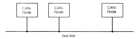
Figure 1 shows a simplified illustration of a bus system according to an
exemplary
embodiment of the present invention. The bus system according to the present
invention is particularly designed and adapted for application in aircraft. To
a large
extent, the bus system according to the present invention corresponds to the
CAN
standard according to DIN ISO 11898, the differences according to the present
invention existing as described in the following, however.
As may be inferred from Figure 1, the bus system according to this exemplary
embodiment is a communication system which has multiple components (nodes)
with
equality of access connected to one another via a two-wire bus, for example.
The
CAN nodes are each connected to the two wires of the bus system.
The bus system is designed for bidirectional communication and for parallel
access of
multiple nodes. The nodes may have different criticality. The nodes all access
the
same transmission system, i.e., the same bus line.
In an aircraft in particular, the differentiation of systems or nodes of
different
criticality is essential. A breakdown of cabin lighting, for example, is to be
handled
with a different priority than a simultaneously occurring breakdown of the
engine
control. Correspondingly, according to the present invention, an
identification field of
the data packet which has a higher priority is provided with a higher message
priority
(e.g., the data packet which relates to the engine control) than, for example,
a lower-
priority data packet (which relates to cabin lighting, fox example).
-3-
CA 02490561 2004-12-21
During data transmission, the individual nodes are not addressed, but rather
the
content of the message is identified through a unique identifier. In addition
to the
content identification, as already noted above, the priority of the data
packet is also
determined. Using the acceptance check which then follows, all stations, i.e.,
all
devices or nodes connected to the bus line, after correct receipt of the
message,
determine on the basis of the identifier whether the data received is relevant
for them
or not. High flexibility is achieved through the content-based addressing.
Stations
may be added to the existing data system very easily.
In addition, the possibility of multicasting results. A message may be
received and
analyzed simultaneously by multiple users. Measured variables which are needed
by
multiple control units as information, for example, may be distributed via the
bus
system in such a way that each control unit does not require its own sensor.
Each user, i.e., each aircraft system or each device which is connected to the
bus line,
may send data without a special request to any master. As in an ethernet, for
example, collisions may occur here, which may be solved using hardware,
however,
and may be con ected through repetition. A collision is recognized in that a
transmitter reads back and compares the transmitted identifier itself. In the
event of
inequality, a user having higher priority was there, which drew the line in
the
dominant level at some point.
The identifier having the lowest binary number thus has the highest priority.
The procedure for collision checking via the identifier may also be referred
to as "bit-
by-bit arbitration". In accordance with a "wired and mechanisms", in which the
dominant state on the bus line (logical zero) exceeds the recessive state
(logical 1 ), all
of the nodes which transmit recessive lose the rivalry for the bus line, but
also observe
the bus as dominant. All "losers" automatically become receivers of the
message with
the highest priority and only attempt to transmit again when the bus becomes
free.
Therefore, a bus system is provided which executes a need-dependent bus
allocation.
-4-
CA 02490561 2004-12-21
Even simultaneous bus accesses of multiple modes must always lead to a unique
bus
distribution. Through the previously described method of bit-by-bit
arbitration via the
identifier of the messages pending for transmission, each collision is
uniquely
resolved after a calculable time. According to the CAN standard format there
are at
most 13 bit characters, in the expanded format there are at most 33 bit
characters.
As may be inferred from the nature of the CAN bus, messages on the bus system
are
exchanged and/or sent on the bus system via the bus line using data packets.
For this
purpose, a message is packaged in the fi~ame form specific for the bus system.
For
example, as already noted above, the format defined in the DIN standard ISO
11898
may be appropriately adapted and used here. Such a data packet may also be
referred
to as a "FRAME". A FRAME comprises seven characteristics, namely the start
condition, the message identifier, control bits, data bits (0 - 8 bytes),
check bits,
acknowledge bits, and stop condition. The start condition and the stop
condition may
be used for synchronization.
FRAMES also differ according to the length of the identifier. There is the
standard
FRAME, which has an 11-bit identifier, and the extended FRAME, which has a 29-
bit
identifier. According to one exemplary embodiment of the present invention,
the
extended FRAME having a 29-bit identifier, which the following description is
also
based on, is preferably used. The 29-bit identifier of the data packet may
also be
referred to as an expanded identification field. One may also differentiate
between
data FRAMES and remote data FRAMES according to the type of the FRAME, this
differentiation not being discussed in greater detail here.
Figure 2 shows an exemplary embodiment of an expanded identification field
which
is a part of the data packet in the bus system according to the present
invention. As
may be inferred from Figure 2, the expanded identification field or the
extended
identifier has a length of 29 bits, the bits being numbered from the least
significant bit
upward to the most significant bit. The bit having the lowest significance LSB
(least
significant bit) is the bit 0 on the right side and the bit having the highest
significance
-5-
CA 02490561 2004-12-21
MSB (most significant bit) is the bit 28 on the left side. The expanded
identification
field, which is shown in Figure 2, is identified with the reference number 2.
The
reference number 4 in Figure 2 identifies the four highest-value bits of the
expanded
identification field 2 and the reference number 8 identifies the six lowest-
value bits or
bits provided with lowest significance of the identification field 2. The bits
6 through
24, which are positioned between the system ID having a length of 6 bits,
comprising
the bits 0 through 5, and the message priority, comprising the bits 25 to 28,
relate to a
function code 6, which may be designed system-specific and has a length of 19
bits.
The function code may, for example, determine the function to be performed by
the
receiver which is addressed using the system ID.
According to an exemplary embodiment of the present invention, prioritization
of
highly-critical systems, i.e., systems having the highest criticality in an
aircraft,
allows, if multiple devices or flight systems access the bus line
simultaneously, the
system having the highest priority to be able to actually access the bus line
and
transmit the corresponding data packet. In this way, it is ensured that no
delays occur
at the critical systems and reliable transmission is ensured.
According to an exemplary embodiment of the present invention, the system ID
which is contained in the expanded identification field in the bits 0 through
5 is
assigned on the basis of ATA chapters of the flight system.
The complete name of this specification is ATA iSpec 2200: Information
Standards
for Aviation Maintenance. The ATA iSpec 2200 arose in the year 2000 through
the
combination of the following two specifications: ACA Spec 100: Manufacturers
Technical Data and ACA iSpec 2100: Digital Data Standards for Aircraft
Support.
The ATA iSpec 2200 relates to technical documentation for aircraft
maintenance. It
comprises an industry-wide standard for numbering aircraft systems. The
numbering
system encountered in all of civil aviation in practically all fields for
hierarchical
organization of the aircraft in "ATA chapters" is essentially from the ATA
Spec 100.
This numbering system was adapted to new technical developments and is now
also
included in the ATA iSpec 2200.
-6-
CA 02490561 2004-12-21
Since an aircraft (possibly only under specific conditions) may be operated
even if
individual parts of the system components have broken down, the master-minimum
equipment list (MMEL) in the ATA iSpec 2200 is a list containing the available
components which are necessary as a minimum for safe operation of the
aircraft. The
MMEL is part of the approval documents of the aircraft.
The "ATA chapters" as the hierarchical organization of the aircraft (ATA
breakdown), originally published in ATA iSpec 100, have permeated all of civil
aircraft construction. These chapters are actually the chapters of the
handbooks,
among other things for the airframe and power plant systems. The aircraft
components, i.e., the aircraft systems, are identified by a code which
comprises three
elements, each having two digits. The code 29-31-03, for example, indicates
system
29, subsystem 31, and unit 03.
Figure 3 shows an exemplary embodiment of a table of how the system IDs are
assigned in regard to the ATA chapters. In other words, according to the
present
invention, the system ID uniquely refers to a corresponding ATA chapter.
Through
the use of the ATA chapters, the aeronautical engineering reliability of the
communication protocol for safety-critical applications in an aircraft is
simplified in
particular.
As may be inferred from Figure 3, the system IDs are coded binary and refer
uniquely
to corresponding ATA chapters. Thus, for example, system ID 110011 refers to
ATA
chapter 71, which relates to the "power plant".
In other words, according to the present invention, a bus system is provided
in which
data packets have an identification field whose six lowest-value bits are
directly
connected to ATA chapters which uniquely identify aircraft systems.
It is to be noted that the coding selected between the ATA chapters and the
system
IDs according to other exemplary embodiments of the present invention may also
be
CA 02490561 2004-12-21
designed differently and the table of Figure 3 is merely to be understood as
an
example.
This advantageously allows the communication of applications and (sub-)systems
of
different criticality on the same data bus medium, i.e., on the same bus line,
which, as
noted above, may be a simple two-wire bus line. Through the use of a shared
data bus
medium, aircraft-side performance weights may be reduced. This also allows
installation costs to be reduced. For the devices, simplification is made
possible by
reducing the plug size (pin number) and a reduced number of data bus
semiconductor
components inside the devices is made possible.
Advantageously, in the course of the aeronautical engineering system approval,
by
determining message priorities in the communication between systems/devices of
different criticality via a shared data bus medium, the aeronautical
engineering
approval is simplified and/or possible at all for the first time for safety-
critical
functions.
Furthermore, the present invention allows the data bus system to be expanded
and/or
the easy addition of further devices (e.g., in the course of a customer-
specific
configuration of the aircraft or when adding further applications) without
applying
software modifications to already existing devices.
_g_