Note: Descriptions are shown in the official language in which they were submitted.
CA 02490641 1994-06-21
65579-91E
Dispenser Gun for Viscous or Semi-Viscous Products
BACKGROUND OF THE ~NVF~NTIDN
The present invention is directed to dispensing devices
for discharging predetermined quantities of, viscous or
semi-viscous materials from the nozzle of a gun-like device
having a manually actuated trigger structure for selectively
discharging the materials from the gun. In particular, the
discharge device of the present invention is primarily
adapted for the application of relatively small quantities
of viscous or semi-viscous liquid insecticides or~ pesticides
i0 to be applied to relatively small target areas ,in accurate
and repeatable sequences. .
The following United States patents represent typical
prior art dispensing devices for discharging liquid
materials, including viscous or semi-viscous materials: U.S.
patent Nos. 3,141,583; 3,517,688; 3,545,680; 4,062,480;
4,.083,474; 4,39.4,945; 4,531,912; 4,678,107; 4,809,885;
4,821,927; 4,923,096; 4,991,747; 5,022,563; 5,064,098;
5,065,910; and 5,137,187.
It is an object of the present invention to overcome
disadvantages of the known prior art dispensing guns: In
particular, the discharge devices encompassed within. the
scope of the present invention provide manually.; actuated
dispensing guns including means for presetting selected
_ 2
CA 02490641 1994-06-21
65579-91E
quantities of material to be discharged from the device, and
assuring that the precisely metered quantity of discharged
material are applied in repeatable sequences at the
selection of the user. The dispensing gun is adapted to
operate as a vacuum driven system, and includes suction
generating means for evacuating a discharge chamber to
prevent dripping of material from the gun after. the desired
quantity of material has been discharged. The dispensing gun
is particularly adapted to the discharge and application of
viscous and semi-viscous materials, and irk particular,
liquid pesticides and insecticides, which, by the nature of
the products, precisely measured, relatively small
quantities of material are discharged and applied to well
defined and closely confined target locations. It is the
further object of the present invention to provide a
dispensing device including means for adjusting one or more
of the preset quantities of material dischargeable from the
gun, and further providing means for readily enabling the
user to discharge the same ,predetermined quantities of
material from the gun in easily repeatable selected
sequences.
Other objects and advantages of the present invention
will become apparent from. the following discussion in
conjunction with the accompanying drawings.
- 3 -
CA 02490641 1994-06-21
65579-91E
SUMMARY OF THE I~1VENTION
The present invention provides a manually operated,
trigger actuated gun-like dispensing device for selectively
discharging predetermined quantities of material through a
discharge nozzle for application of the discharged material
to a predetermined target location. The dispensing device
is particularly adapted to selectively discharge one or more
preselected, relatively small quantities of viscous or
semi-viscous material, particularly-liquid insecticides or
pesticides or other similar materials, in precisely metered,
adjustable quantities, and in readily repeatable sequences.
The dispensing device includes a housing section for
removably receiving a replaceable container holding the
material to be dispensed from the device. A manually
actuated, spring. biased trigger is included within a handle
section of the device, and means are provided for adjusting
and limiting the relative movement of the trigger to
discharge one or more different predetermined quantities of
material from a forward discharge nozzle of the dispensing
device. Actuation of the trigger advances a piston in a
forward direction to expel either viscous or semi-viscous
material from a forward discharge chamber of the dispensing
device by decreasing the volume of the forward chamber and
increasing the pressure therein, and to subsequently draw
- 4 -
CA 02490641 1994-06-21
65579-91E
additional material into the discharge chamber through the
creation of a partial vacuum as the chamber volume expands
when the piston retracts into its relaxed position as a
result of a resilient bias applied thereon. Material
remaining in the forward nozzle and not discharged therefrom
during the forward discharge stroke of the piston is drawn
back into the forward discharge chamber around a
displaceable flap covering a .forward outlet opening in the
discharge chamber. The flap is displaced by the partial
vacuum created as a result of the rearward return movement
of the piston towards its relaxed operating position,
thereby avoiding the undesirable accumulation of
non-discharged residual material in the discharge nozzle and
the resulting continuous discharge of dripping material
after the piston has completed its forward~discharge stroke.
Accordingly, both the discharge of material from the
discharge chamber during the forward piston stroke and the
reloading of the discharge chamber (including both the
forward evacuation of material from the rearwardly disposed
supply container, and rearward evacuation of any residual
material remaining in the forward discharge nozzle from the
previous discharge stroke) during the return piston stroke,
is accomplished by a system which is primarily vacuum driven
as a result of the creation of pressure differentials in the
discharge chamber.
- 5 -
CA 02490641 1994-06-21
65579-91E
The dispensing device of the' present invention is
adapted to discharge precisely measured quantities of
viscous or semi-viscous material, preferably relatively
small quantities of insecticide or pesticide, in a
repeatable sequence. The dispensing device employs
structure and and operative relationship of structure,
including an adjustable volume discharge chamber with a
cooperating rear valve and forward flap, to both discharge
precisely measure small quantities of viscous or
semi-viscous materials, and to automatically reload the
discharge chamber by evacuation of material from the
rearwardly positioned liquid reservoir and by simultaneous
evacuation of non-discharged material 'from the forwardly
positioned discharge nozzle. Although the dispensing device
of the present invention is intended to apply relatively
small quantities of viscous or semi-viscous insecticide or
pesticide, it is nonetheless within the scope of the
invention to use the device for applying materials other
than insecticides or pesticides.
In the. preferred embodiments of the invention, the rear
end of the product tube received within the dispensing gun
is crimped to provide stop means for retaining. a discharge
piston securely within the product ~ tube. The adapter
receiving the product tube is provided with means f or
- 6 -
CA 02490641 1994-06-21
65579-91E
venting air from the adapter as the adapter and product tube
are removably received within the pump housing of the
dispensing device to prevent air from mixing with the
product. A cap which is removably mounted over the
discharge end of the product tube and adapter before the
product tube and adapter are received within the pump
housing of the device, is also provided with vent means to
prevent air from mixing with the product within the tube
while the cap is mounted to the discharge end-~thereof.
Venting means provided in the adapter and the cap prevent
air from being entrapped with the product in the tube and
avoid the potential undesirable loss of prime to the pump
which might, otherwise result from air mixing with the
product within.the tube.
In accordance with a further embodiment of the
present invention,.there is provided in a device for
dispensing selected quantities of liquid product, said
device comprising a housing having an inlet end defining
an inlet opening and an outlet end defining a discharge
opening, and pump means for causing said liquid product to
flow between said inlet opening and said discharge opening
of said housing, the improvement comprising: a product
reservoir removably mountable to said housing in fluid
communication with said inlet opening defined in .said
housing, said product reservoir including a piston
received therein for discharging product from said product
CA 02490641 1994-06-21
65579-91E
reservoir, said product reservoir including stop means
proximate to a rear end thereof for preventing rearward
movement of said piston beyond said stop means, said product
reservoir removably received within an adapter, said adapter
being removably mountable to said housing in an operating
position therein for providing fluid communication between
the product within said product reservoir and said inlet
opening of said housing, and means for venting air from said
housing as said adapter and said inlet opening of said
housing are moved in a relative direction towards each
other.
In accordance with yet another embodiment of the
present invention, there is provided in a device for
dispensing selected quantities of liquid product, said
device comprising a housing having an inlet end defining an
inlet opening and an outlet end defining a discharge
opening, and pump means for causing said liquid product to
flow between said inlet opening and said discharge opening
of said housing, the improvement comprising: a product
reservoir removably mountable to said housing in fluid
communication with said inlet opening defined in said
housing, said product reservoir including a piston received
therein for discharging product from said product reservoir,
said product reservoir including stop means proximate to a
rear end thereof for preventing rearward movement of said
piston beyond said stop means, said product reservoir
removably receivable within an adapter, said adapter being
removably mountable to said housing in an operating position
therein in fluid communication with said inlet opening
defined in said housing, said adapter defining an outlet
opening for discharge of liquid product from said reservoir,
and a cap removably mountable over said outlet opening of
- 7a -
CA 02490641 1994-06-21
65579-91E
said adapter, said cap defining therein means for venting
R
air from said adapter when said cap is mounted to said
outlet opening in said adapter.
In accordance with yet another embodiment of the
present invention, there is provided a device for
discharging material from a housing in response to actuation
of a trigger, said device including the housing, the
trigger, and a handle extending from said housing, the
trigger being selectively movable relative to said handle,
and means for discharging a preselected quantity of material
from said housing in response to predetermined movement of
said trigger relative to said handle; said device including
means for adjusting the range of movement of said trigger
relative to said handle for vaxying the quantity of material
to be discharged from said housing, said means for adjusting
including an insert on said handle, said insert adapted to
receive an adjustment member extending into said handle
through an opening defined in said insert, said insert
including means for adjusting the distance which said
adjustment member extends into said handle, and a trigger
stop mounted to said trigger and movable therewith such that
said trigger stop abuts against a forward end of said
adjustment member to limit movement of said trigger relative
to said handle, said trigger stop defining an opening
therein, and means for selectively adjusting the position of
said adjustment member extending into said handle such that
said adjustment member is in or out of alignment with said
opening, wherein said maximum movement of said trigger
relative to said handle is permitted when said adjustment
member is aligned with said opening in said trigger stop and
said adjustment member is received within said opening.
- 7b -
CA 02490641 1994-06-21
65579-91E
BRIEF DESCRIPTION OF THE DRAWINGS
FIGURE 1 of the drawing illustrates a sectional view of
a dispenser gun in accordance, with the present invention;
FIGURE 2 of the drawing illustrates the forward portion
of a discharge chamber of the dispenser gun shown in Figure
1;
FIGURE 3 of the drawing illustrates, in perspective, a
portion of the handle section of the dispenser gun which
acts as an adjustable stop element for metering the quantity
of material to be discharged from the dispensing device upon
actuation of a trigger .element;
FIGURE 9 of the drawing illustrates a rear elevational
view, in section, of the dispensing gun shown in Figure 1
illustrating a removable reservoir retained within the
housing and an adjustment element on the handle section for
setting a predetermined quantity of material to be
discharged from the dispenser gun upon actuation of the
trigger of the gun; v
_ g _
CA 02490641 1994-06-21
65579-91E
FIGURES 5A and 5H illustrate a further modification of
the product tube providing means for retaining a discharge
piston therein;
FIGURES 6A and 6H illustrate venting means in the
product tube adapter to prevent air from mixing with
product within the tube during the mounting of the product
tube and adapter to the pump housing; and
FIGURES 7A, 7B and 7C illustrate a cap removably
mounted to the discharge end of the product tube including
venting means for preventing air from mixing with the
product within the tube during mounting of the cap to the
tube.
- 9 -
CA 02490641 1994-06-21
65579-91E
DETAILED DESCRIPTION OF THE PREFERRED
EMBODIMENTS OF THE INVENTION
The structure and operation of a dispensing device in
accordance with 'the present invention will now be described
in greater detail with respect to the accompanying drawing
figures.
Figure 1 of the drawing illustrates the preferred
embodiment of a dispenser device for viscous or semi-viscous
liguids in accordance with the present invention. The
dispensing device includes a longitudinally extending
housing section generally designated by the reference
numeral lA, a rear end cap 1 pivotably mounted to the rear
of the housing lA for removably mounting a reservoir 2.
containing a viscous or semi-viscous liquid material to the
housing lA, and a handle section generally designated .by
reference numeral 25A extending downwardly from the lower
surface of the housing 1A. A discharge needle 16 defining a
discharge opening at the forwardmost end thereof extends
from a nozzle cap 15 mounted to the forwardmost end of the
dispenser housing lA.
An adapter 3 and an adapter O-ring 4 are provided as
part of the forward assembly of the discharge end of the
removably mounted liquid containing reservoir 2. A cylinder
surrounds the O-ring 4 to firmly maintain a sealing
engagement of the discharge end of the product reservoir
- l0 -
CA 02490641 1994-06-21
65579-91E
container 2. A hollow piston 6. defining a centrally
disposed bore extending therethrough is ,mounted forward of~
the discharge end of the reservoir 2, and the bore of the
piston is in substantial axial alignment with the tapered
discharge end of the~_reservoir 2. In this manner, as will
be discussed in greater detail below, liquid from, the
reservoir 2 flows from the discharge opening in the
reservoir in a substantially straight or longitudinal path
directed forwardly into the centrally disposed bore. defined
in the piston. A portion of an outer surface of the piston
6 .defines a notch or recessed section for receiving the
remote end of a steel trigger bar 18. As will also be
discussed in greater detail below, the coupling of the
trigger bar 18 to the piston enables selective movement of
the piston upon actuation of the trigger to discharge
material from the forward needle 16 of the dispensing gun.
A pair of O-rings 7 are disposed around the cuter
surface of the piston 6 to provide sealing engagement
therewith. The forward end of the centrally disposed bore
defined within the~piston 6 terminates in a check.valve 9
which includes an 0-ring 8 to enhance the sealing integrity.
of the valve. The check valve 9 includes a longitudinally
extending spring 10 which exerts a resilient force' on the
ball valve 9 to maintain the valve in a sealing relationship
- 11 -
CA 02490641 1994-06-21
65579-91E
against the forward opened end of the centrally disposed,
longitudinally extending bore defined within the piston 6:
Accordingly, the spring 10, in its relaxed normal operating
position, will maintain the check valve in a closed position
to seal the forward end of the bore defined in the piston.
A forward discharge chamber 32 is defined between a
pair of opposed, longitudinally extending sidewalls 33
fixedly mounted relative to the housing lA. The rear end of
the discharge chamber is defined by the forward end of the
piston 6, including the ball valve 9 seated in the forward
discharge end of the bore defined within the piston. The
forward end of the discharge chamber is defined by a flap
valve assembly comprising a flap housing 12 and a flap
element 13 movably secured to the forward end of the flap
housing 12 and adapted to selectively cover one or more
bores defined in the forward end of the flap housing and
extending therethrough in fluid communication with the
discharge chamber 32. The flap is mounted to the forward
surface of the flap housing by a rivet 14. The forward
assembly of the dispensing device further comprises a collar
17 mounted around a portion of the tapered forward end of
the housing section lA, and a nozzle cap 15 extending
forward of the collar 17 and providing means for mounting
the discharge needle 16 therein such that the discharge
- 12 -
CA 02490641 1994-06-21
65579-91E
needle is in substantial alignment with the substantially
axially directed flow of material from the forward discharge
chamber 32, as will be discussed in greater detail below.
The handle section 25A of the dispensing gun generally
comprises a downwardly extending handle 25 fixedly mounted
relative to the longitudinally extending housing lA. A
movable trigger section 19 is pivotably mounted-relative to
the handle section 25 by a pivot pin 20. Relative movement
of the trigger 19 towards the handle 25 results in forward
movement of the trigger~bar 18 to advance the piston 6 which
is coupled to the trigger bar in the manner previously
described herein. A trigger spring 26,vwhich is mounted to_
the handle section 25 by means of mounting screws 27,
resiliently biases the trigger 19 away from the handle
section 25. Accordingly, when manual pressure is released
from the trigger section 19, the trigger spring 26 causes
movement of the trigger 19 away from the handle section 25,
which in turn causes the piston bar 18 to retract the piston
6 rearwardly in the housing section lA to supplement the
resilient force also applied in a rearwardly direction to
the piston 6 by the spring 10 as previously discussed.
Still referring to Figure 1 of the drawing, the~handle
section 25 includes a threaded insert 24 directed into the
- 13 -
CA 02490641 1994-06-21
65579-91E
handle for receiving ,an adjustment ~scre~l 23 in an opening
defined in the insert. The adjustment screw cooperates with
a trigger stop 22 fixedly mounted on the trigger 19 and
pivotably movable therewith, to adjust the maximum permitted
range of movement of the trigger section 19 relative to the
handle section 25 to control the quantity of material.
discharged from the dispensing gun by controhling the extent
of movement of the piston 6 into the discharge chamber 32.
As more fully illustrated by Figure 3, the trigger stop
22 is formed from a substantially U-shaped bar having a
middle section 40 and two opposed sidewalls 41 and 42. An
opening 43 is defined in the approximate center ~of the
middle section 40 of the stop element 22. The opening 43 is
sufficiently large to receive therethrough the adjustment
screw 23 extending into the handle section 25 when the
trigger is moved relative to the handle and the adjustment
screw is aligned with the opening 43 in the trigger stop 22.
When such alignment occurs, the trigger is movable through
its maximum range relative to the handle. When more
restrictive movement is desired, the insert ~24 i's movable
relative to the.handle 25 and the trigger stop 22 such that
the opening 43 is no longer in alignment with the adjustment
screw 23 extending into the handle. (The manner in which the
insert 24 is movable relative to the trigger stop 22 is
- 14 -
CA 02490641 1994-06-21
65579-91E
further described in the discussion of Figure 2). When the
screw and opening are out of alignment, relative movement of
the trigger towards the handle is impeded by the screw which
abuts against a closed surface portion of the middle section
40 of the trigger stop 22, as illustrated by the reference
numeral 23' in Figure 3. The extension of the screw 23 into
the handle section 25 is variable so as to adjust the range
of relative movement between the trigger and the handle
before said relative movement is stopped by the abutment of
the forward end of the screw 23 against the stop 22. In
this manner, the quantity of material discharged from the
dispensing device is variable by adjusting the range of
maximum relative movement between the trigger and the handle
which directly corresponds to the forward movement of the
piston 6 in the housing lA which also corresponds to the
quantity of material discharged from the discharge chamber
32. Accordingly, the predetermined quantity of material to
be discharged from the dispensing gun is controlled and
selectively adjusted as a result of cooperation between the
position of the trigger stop 22 relative to the insert 24 on
the handle 25, and also the distance which the .adjustment
screw 23 extends into the handle section 25.
Referring to Figure 2 of the drawing, a rear
elevational view of the dispensing gun is illustrated
- 15 -
CA 02490641 1994-06-21
65579-91E
partially in section. The handle 25 is formed from two
separate halves 29 and 30 which are mated together by
conventional means such as .the collar 17 illustrated in
Figure 1. A rectangular opening 45 is defined generally in
the center of the handle 25. A slide element 44 is movable
within the opening 45, and the slide 44 carries the threaded
insert 24 for receiving the adjustment screw 23 (See Fig.
1). Accordingly, movement of the slide element 44 in the
opening 45 relative to the handle section 25 correspondingly
moves the threaded insert 24 and the adjustment screw
received therein, selectively into and out of alignment with
the opening 43 in the trigger stop 22 (See Fig. 3). As
previously discussed, axial alignment and non-alignment of
the adjustment screw 23 carried by the handle 25 with the
opening 43 in the trigger stop 22 carried by the trigger 19
controls the maximum permitted range of relative movement
between the trigger 19 and the handle 25.
Still referring to Figure. 2, the housing lA removably
receives a product container tube 2 when the rear end cap 1
hingedly mounted to the rear of the.housing is pivoted into
an open position. The housing defines two opposed
extensions 29A and 30A for removably receiving complementary
configured grooves in hinged cap 1. The complementary
configured extensions and grooves assure a firm friction fit
- 16 -
CA 02490641 1994-06-21
65579-91E
between the hinged cap 1 and the housing lA. The product
container 2 is then removably received within housing lA and
the hinged cap 1 is pivoted into its closed position as
illustrated .in Figure 1.
The operation of the dispensing gun in accordance with
the present invention will now be discussed with reference
to Figures 1 and 4 of the drawing. Referring first to
Figure 1, actuation of the trigger 19 by manual movement.
thereof towards the handle 25, against the bias of trigger
spring 26, causes forward movement of the trigger bar 18.
The trigger bar is coupled to the piston 6, as previously
described, such that advancement of the trigger drives the
piston forward .in the housing in a direction towards the
discharge needle 16. More specifically, as the piston 6
advances forward into the discharge chamber 32, the forward
end of the bore extending through the piston is sealed as a~
result of the resilient force applied on a check valve 9 by
a-valve spring 10 to seat a ball on the discharge end of the
bore to seal the forward .end of the bore defined in the
piston adjacent to the discharge chamber 32. Forward
movement of the piston into the discharge chamber 32
decreases the volume of the chamber, thereby increasing the
pressure therein, to force materia l within the chamber
forwardly through a plurality of discharge ports 50 and 52
- 17 -
CA 02490641 1994-06-21
65579-91E
(illustrated by Figure 4) defined in the outlet end of the.
discharge chamber. The~material flows through the discharge
needle 16 and is discharged from the dispensing gun and
applied to a predetermined target area. As previously
discussed, the relative movement of the trigger l9 towards
the handle 25 is adjustable to control the forward movement
of the piston 6 into the discharge chamber 32, thereby
controlling the quantity. of material discharged from the
dispensing gun in response to actuation of the trigger.
Figure 4 of the drawing illustrates the forward outlet
end of the discharge chamber 32 in greater .detail. A
forward discharge end wall 48 defines at least one discharge
port (50, 52). A displaceable flap 13 is mounted to the
outer surface of the forward end wall 48 by a rivet 14, and
preferably at least one discharge outlet port (50, 52) is
disposed on each side,of the rivet 14. The flap housing 12,
as illustrated in Figure 1, defines the discharge chamber 32
between the opposed sidewalls 33 and the forward end wall
48. The flap is formed from a pliable material, preferably
a latex material, having a thickness in the order of
1/30,000 inch: As the pressure in the discharge chamber 32
is increased by the forward movement of the piston 6, the
material within the discharge chamber 32 is forced to flow
forwardly through the outlet ports (50, 52) in the end wall
- 18 -
CA 02490641 1994-06-21
65579-91E
48, displacing the portions of the flap 13 covering the
ports, so that the material is discharged through the out 1 et
ports. The discharged material flows through~the ports and
into the forward needle. 16, to be discharged from the
dispensing gun.
After a predetermined guantity of material has been
discharged from the dispensing gun as described above (the
guantity of discharged material having been preselected as a
result of adjustment of the~trigger control means previously
discussed herein), the trigger 19 is forced to move iri a
direction away from the handle 25 as a result of the
resilient force applied to the trigger by the trigger spring
26. The relative movement of the trigger in a direction
forwardly away from the handle 25 causes the trigger bar 18
to be retracted in a direction towards the rear of the
longitudinally extending housing lA. The rearwardly
retracted movement of ~ the trigger . bar causes rearward
movement of the coupled piston 6 relative to the discharge
chamber 32. The rearward movement of the piston 6 is
further supplemented by the resilient force applied by the
valve spring l0 on the forward end of the piston 6 as the
valve spring returns to its relaxed position. As the p i stern
6 is moved in a rearward direction, the discharge chamber 32
increases in volume, thereby decreasing the pres sure
- 19 -
CA 02490641 1994-06-21
65579-91E
therein. As a result of the reduced pressure in the
discharge chamber 32, suction is generated drawing material
from the discharge outlet. of the rearwardly disposed product
container tube 2 forwardly through the bore in the piston 6,
and into the forward discharge chamber 32. The forward flow
of material through the bore in the piston as a result of
the reduced pressure in the discharge chamber causes
displacement of the ball valve 9 from the valve seat to
unseal the forward discharge end of the bore in the piston
to permit flow of material from the bore and into. the
forward discharge chamber. Simultaneously with the forward
flow of material from the rearwardly disposed product
container' tube 2, residual material which may still remain
in the discharge needle 16 (or in other positions forward of
the discharge chamber 32) is drawn rearwardly into the
discharge chamber 32 as a result of the decreased pressure
within the discharge chamber. The material drawn rearwardly
displaces the flap 13 so as to enter the discharge chamber'
32 through the ports 5o and 52. Directional arrows 54 of
Figure 4 illustrate the forward flow of material out from
the discharge ports (50, 52) towards the forward needle 16,
while directional arrows 56 illustrate the path of fluid
flow of material from the discharge needle back into .the
discharge chamber 32 through the ports (50, 52). hn both
directions of flow, the pressure. ~diff erential in the
CA 02490641 1994-06-21
65579-91E
discharge chamber causing the flow of material al so
displaces the flap 13 to open the ports (50, 52) to enable
flow of material through the ports both into and out of the
discharge chamber 32. Accordingly, the decreased pressure
in the discharge chamber 32 resulting from the rearwa rd
movement of the piston 6 reloads the discharge chamber with
material to be subsequently discharged from the dispensing
gun by both drawing material forwardly from the rearward ly
disposed product container 2, and simultaneously drawing
residual material remaining in the needle 16 rearwardly:back
into the discharge chamber 32. The rearward flow of
residual material also serves to prevent dribbling or
dripping of this material from the needle to assure that
only precisely measured quantities of material are applied
during the discharge phase of the dispensing gun only when
the trigger is actuated by the user.
It is apparent from the above discussion that the
dispensing gun in accordance with the present invention is a
vacuum driven system which is adapted to efficiently
discharge and deliver precisely metered, pre-selected
quantities of material to be applied to a target area in
repeatable sequences. The system is designed to operate
primarily on pressure differentials generated within the
dispensing apparatus, causing fluid flow in a substantially
- 21 -
CA 02490641 1994-06-21
65579-91E
linear direction through the gun housing. The dispensing
gun includes cooperating structure for automatically
reloading the discharge chamber for subsequent discharge of
material, said reloading occurring simultaneously from a
rearwardly disposed product reservoir container, and from
f orwardly disposed residual material remaining in the device
from a prior discharge procedure. The residual material
drawn back into the discharge chamber from the forward
discharge needle of the device acts to prevent dripping or
dribbling of this material from the dispensing device after
a discharge sequence. In this manner, precise and
preselected quantities of material will be delivered from
the dispensing device during a subsequent discharge
operation. A displaceable flap is provided to removably
cover at least one outlet port defined at the forward end of
the discharge chamber by cooperating 'with increased and
decreased pressure generated in the discharge chamber by
advanced and retracted movement of the discharge piston in
response to actuation of the trigger.
Preferably, the dispensing gun is designed to deliver
precisely metered materials in quantities as small as .007
grams in repeatable sequences. The adjustment means for
controlling the range of relative movement between the
trigger and the handle of the dispensing gun to preselect
- 22 -
CA 02490641 1994-06-21
65579-91E
the quantity of material to be' discharged from the
dispensing gun, assures that. materials will be discharged
from the dispensing gun in the same preselected quantities
in repeatable sequences, as.is desired by the user'. The
control means also enables. adjustment of the preselected
guantity of material to be discharged during actuation of
the trigger, at the selection of the user. The dispensing
gun is designed such that relatively large movements of the
trigger relative to the, handle are translated into,
relatively small displacements of the piston into the
discharge chamber to enable the precise discharge of small
quantities of product. The dispensing device is also
designed such that flow of material through the dispensing
housing is substantially linear to promote efficient
discharge of material from the vacuum driven device.
Although the device is primarily adapted to discharge
viscous and semi-viscous material including pesticides .and
insecticides, it may nonetheless be used for dispensing
other types of material.
Figures 5A and 58 illustrate a further modification of
the dispensing gun in accordance with the present invention.
Figure 5A is a side elevational view, in section, of the
product tube Z including a tube piston 60 received therein.
The piston is movable within the product tube in a forward
- 23 -
CA 02490641 1994-06-21
65579-91E
direction towards a front discharge nozzle 62 to discharge
product 64 stored within the tube. The tapered forward.
discharge end 66 of the product tube is threadably received
within a correspondingly configured outer adapter 68, and a
frontwardly mounted 0-ring 70 seals the front discharge end
72 of the outer adapter.
The combined structure of the product tube 2 received
within the outer forward adapter 68 is itself .removably
received within the pump housing of the dispensing device of
the present invention as discussed with respect to Figure 1.
At least one detent 74 is formed in the product tube 2 by
inwardly crimping at least one portion of the product tube
behind the position of the tube piston 60. As illustrated
in .Figures 5A and 5B (which is a cross-section taken along
line 5B of Figure 5A), twv separate crimped portions 74 are
deffined on the circular outer periphery of the product tube
2. The crimped portions 74,~which are spaced apart from
each other by an angle of approximately 100 degrees,
provides stop means for defining the rearmost position of
the tube piston 60 relative to the product tube 2... In the
event that forces or pressure are inadvertantly applied to
the center of the product tube causing fluid pressure to be
exerted rearwwardly on the tube piston 60, the stop means 74
prevent the tube piston itself from. being propelled out from
- 24 -
CA 02490641 1994-06-21
65579-91E
the rear of the piston tube which would thereby result in
loss of the product 64 through the rear end of the product
tube 2.
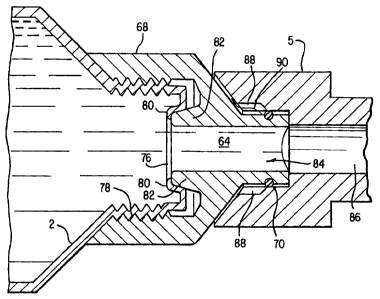
Figures 6A and 6H disclosed further modifications to
the combination of the adapter 68 and the product tube 2
received therein, as illustrated by Figure 5A. Figure 6A
illustrates the adapter and -product tube in an operative
position removably received within the pump housing 5 of the
dispensing device in accordance with the present invention
(See Figure 1 of the drawing). Figure 6E illustrates the
forward end of the product tube, including .a discharge
orifice 76 defined by a forward rim 80, in a rion-operative
position in which the product tube 2 is not retained within
the product tube adapter 68 by the complementary screw
threads 78. When the forward end of the product tube 2 is
screwed into the product tube adapter 68 by the threads 78,
as illustrated by Figure 6A, a rearwardly extending annular
protrusion 82, defined integrally on the product tube
adapter 68, abuts directly against the rim portion 80 of the
front end of the product tube, slightly displacing.the rim
in a rearward direction. In this manner, an. airtight seal
is formed between the forward end of the product tube and
the adapter when the product tube is' received within the
adapter 68 to avoid any leakage or prevent the introduction
- 25 -
CA 02490641 1994-06-21
65579-91E
of air as the liquid product 64 flows. through the discharge
orifice 76 of the product tube and into a product chamber .84
defined by the adapter 68, as.discussed below.
still referring to Figure 6A, the product tube adapter
68 defines a central chamber 84 for receiving product 64
from the product tube, when the product tube is received
within the adapter. The chamber 84 defined by the adapter
is aligned at the rear end thereof with the orifice 76
defined at the forward end of the product tube, and is
la aligned with a hollow bore 86 defined within the pump
housing 5 at the forward .end of the chamber- 84.
Accordingly, in operation of the dispensing device, product
is discharged from the product tube 2 through the forward
orifice 76, into the chamber 84 and through the hollow bore
86.
When the discharge device is in its operative position,
the product tube and adapter are removably received within
the pump housing 5, as illustrated by Figure 6A. The pump
housing 5 and the adapter 68 are configured so ws to_ define
venting means therebetween, illustrated by vent .groove 88.
As 'the product tube and adapter are advanced forwardly into
the rear portion of the pump housing 5 for remova bly
mounting the tube and adapter to the pump housing (as, f or
26
CA 02490641 1994-06-21
65579-91E
example, after the tube has been removed to be refilled with.
product), air occupying~the .space at the rear of the pump
housing is vented through the groove 88 as the adapter is
moved into its operating position relative to the rear space
defined at the rear end of the pump housing. In this
manner, air does not enter the opened forward end of the
product chamber 84 of the adapter 68, but air is vented away
from the product tube and adapter through the vent groove 88
along a path illustrated by the arrows designated by
reference numeral 90. In this manner, air will not mix with
the product within. the tube, thereby avoiding undesirable
results such as loss of pump prime as a result of air mixed
with the product to be discharged by the dispensing device.
Referring now to Figures 7A, 7B and 7C of the drawing,
Figure 7C, illustrates, in perspective, a cap 92 to be
removably mounted over the discharge end of the adapter 68
when the product tube 2 is received therein. More
specifically, as illustrated by Figure 7A, the cap 92 seals
the opened forward end of the product chamber 84 defined by
10 the adapter 68. The cap is removably mounted over the
forward end of the adapter with the product tube received
therein when the adapter and the tube filled with product
are being stored or transported for insertion into the pump
housing 5 of the dispensing device. For example, when a
- 27 -
CA 02490641 1994-06-21
65579-91E
product tube within the dispensing device is depleted, the ..
product tube and the adapter are removed from the pump
housing to be refilled with additional product. After the
product' tube has been refilled, the cap 92 is removably
mounted over the discharge end of the adapter to prevent
loss of product as the tube is being transported back to the
dispensing device to be removably mounted back into the pump
housing 5 (as illustrated by Figure 6A). It is noted that
as the product tube is filled or refilled through the
forward chamber 84 of the adapter and the adjacent forward
orifice 76 of the tube 2, the rear of the product tube is
sealed during the forward refilling -operation by the tube
piston 60 and the stop means 74, as illustrated by Figure
5A.
After the product tube is removed from the pump housing
of. the dispensing device and refilled with product ~to be
discharged therefrom, the cap 92 is mounted over the forward
discharge end of the adapter to prevent inadvertant loss of
product before the product tube and adapter are remounted
into the pump housing of the dispensing device. As
illustrated in greater detail by Figure 7H, a ~downwardly
extending skirt portion 94 of the cap 92 defines an inwardly
directed ramp segment 96. Vent grooves are definedwith in
the ramp 96 for venting air therethrough as the cap 92 is
28
CA 02490641 1994-06-21
65579-91E
removably mounted over the forward end of the adapter 68.
The ramp 9b also engages the O-ring 70 mounted around the
forward end of the adapter 68 to provide a more secure
retention of the cap on the adapter. The vent grooves 96
provide means for venting air away from the forward end of
the adapter as the cap 92 is advanced over the adapter. In,
this manner, air is not entrapped within the adapter, and
does not mix with the product within the adapter and the
product tube, as the cap is placed over the adapter. As
previously discussed with respect to the vent means provided
in the adapter itself, the introduction of air into the
product to be discharged from the product tube results in
undesirable effects including the possible loss of pump
prime during operation of the dispensing device. The cover
92 includes a lower, outwardly extending flange portion to
enable easy mounting and removal of the -cap to and from the
forward discharge end of the adapter 68.
Other modifications and advantages of the dispensing
gun within the scope of the present invention will become
apparent to those skilled in the art. Accordingly, the
discussion of the preferred embodiments of the invention
herein is intended to be illustrative only, and not
restrictive of the scope of the invention, that scope being
defined by the following claims and all equivalents thereto.
- 29 -