Note: Descriptions are shown in the official language in which they were submitted.
CA 02490752 2004-12-21
WO 2004/000405 PCT/US2003/019769
Attorney Docket No. 905.032W01
ARTICULATING HANDLE FOR A DEFLECTABLE CATHETER
AND METHOD THEREFOR
Technical Field
The present invention relates generally to deflectable catheter assemblies.
More particularly, it pertains to an articulating handle for a deflectable
catheter.
Background
Increase in the use of stems, leads, and ablation techniques in branch
vessels has provided an increased demand in the placement techniques for the
devices. For some procedures, it is necessary to initially position a
guidewire
into a desired part of the lumen of a desired vessel or duct, such as a blood
vessel. After the guidewire is positioned within the desired location, a
catheter or
other tubular device may be positioned over the guidewire and used to convey
other medical instruments into the desired blood vessel or duct.
Alternatively, a guiding catheter is used to negotiate the vasculature of a
patient. One example of a guiding catheter is described in U.S. Pat. No.
4,898,577 to Badger et al. The Badger guiding catheter includes a single
elongate shaft that has a deflectable distal portion controllable by a pull
wire.
Once the distal portion is at the required deflection or location within the
patient,
the guidewire or medical instrument is fed through the catheter.
The deflectable catheter is controlled at a proximal end of the catheter by
a control handle that operates the pull wire to deflect the catheter, for
example,
as shown in U.S. Patent No. 6,171,277. However, with conventional catheter
steering mechanisms, it is sometimes difficult to accurately position the
catheters
in certain body vessels, such as branch veins. For instance, the mechanisms
are
awkward or require the use of two hands. It is also awkward since the user
cannot readily discern whether the distal end of the catheter is moving or is
being
controlled by the control handle. Other steering mechanisms require pull wires
1
CA 02490752 2004-12-21
WO 2004/000405 PCT/US2003/019769
Attorney Docket No. 905.032W01
to be wound and unwound around a rotatable cam wheel, causing increased
fatigue on the pull wires, and potentially shortening the life of the device.
What is needed is a deflectable catheter that overcomes the shortcomings
of previous deflectable catheters. What is further needed is a deflectable
catheter
that allows for more accurate positioning of the distal end of the deflectable
catheter, and that is usable with a single hand.
Summary
A catheter assembly includes a handle assembly, and a catheter body
coupled with the handle assembly, where the catheter body extends to a
deflectable
distal end, and the deflectable distal end is controllable by a flexible
element. An
actuator member is coupled with the flexible element, and movement of the
actuator
member provides for movement of the flexible element. In one option, the
actuator
has a locked mode and an operational mode, where the actuator and the flexible
element are not movable relative to the handle assembly when the actuator is
in the
locked mode. There are several options as discussed throughout the
application.
The deflectable catheter allows for single handed precise movement of the
distal tip, and allows for locking a position in place easily. The lock
further assists
in preventing inadvertent movement of the distal tip, for example, during an
ablation procedure. Furthermore, with the above-described design, the distal
end
can be easily configured to have different radius of curvature by varying the
stroke
length. Another option is to vary the input/output of the actuator by
modifying the
gear ratio. A further benefit of the device is the feedback provided when the
lock
is released, for example, the audible click. This affirmatively informs the
physician
when the steering mechanism is placed in the operational mode and/or the
locked
mode, and when the distal end is moving or being actively controlled.
These and other embodiments, aspects, advantages, and features of the
present invention will be set forth in part in the description which follows,
and in
part will become apparent to those skilled in the art by reference to the
following
description of the invention and referenced drawings or by practice of the
invention.
The aspects, advantages, and features of the invention are realized and
attained by
2
CA 02490752 2004-12-21
WO 2004/000405 PCT/US2003/019769
Attorney Docket No. 905.032W01
means of the instrumentalities, procedures, and combinations particularly
pointed
out in the appended claims and their equivalents.
Brief Description of the Drawings
Figure lA is a perspective view illustrating a deflectable catheter
assembly constructed in accordance with one
embodiment.
Figure 1B is a perspective view illustrating a deflectable catheter
assembly constructed in accordance with one
embodiment.
Figure 2 is a perspective view illustrating a deflectable catheter
body constructed in accordance with one embodiment.
Figure 3 is a perspective view illustrating a distal portion of the
deflectable catheter body constructed in accordance with
one embodiment.
Figure 4 is a perspective view illustrating a handle assembly
constructed in accordance with one embodiment.
Figure SA is an exploded view illustrating a portion of a catheter
assembly constructed in accordance with one
embodiment.
Figure SB is an exploded view illustrating a portion of a catheter
assembly constructed in accordance with another
embodiment.
Figure 6 is a side view illustrating a portion of the catheter
assembly in a locked mode constructed in accordance
with one embodiment.
Figure 7 is a side view illustrating a portion of the catheter
assembly in an operational mode constructed in
accordance with one embodiment.
3
CA 02490752 2004-12-21
WO 2004/000405 PCT/US2003/019769
Attorney Docket No. 905.032W01
Descr~tion of the Embodiments
In the following detailed description, reference is made to the
accompanying drawings which form a part hereof, and in which is shown by
way of illustration specific embodiments in which the invention may be
S practiced. These embodiments are described in sufficient detail to enable
those
skilled in the art to practice the invention, and it is to be understood that
other
embodiments may be utilized and that structural changes may be made without
departing from the scope of the present invention. Therefore, the following
detailed description is not to be taken in a limiting sense, and the scope of
the
present invention is defined by the appended claims and their equivalents.
Figures lA and 1B illustrate a deflectable catheter assembly 100, where
Figure lA illustrates the deflectable catheter assembly 100 in an articulated
position, and Figure 1B illustrates the deflectable catheter assembly 100 in
an
unarticulated position. The deflectable catheter assembly 100 includes a
deflectable catheter body 110 and a handle assembly 150 that houses steering
mechanisms for deflection of the catheter body 110. The handle assembly 1 S0,
as described in greater detail below, allows for the deflection of a distal
end of
the catheter body 110. In one option, the pull wire 120 (Figure 2) is
connected
to an actuator that is slid or rotated to apply tension to the pull wire 120
(Figure
2). As tension is applied to the pull wire 120 (Figure 2), the pull wire
anchor at
the distal end of the catheter body 110 is pulled which causes the distal
portion
of the catheter body 110 to curve in a predetermined direction or directions.
With reference to Figure 2, the catheter body 110 comprises, in one
option, an elongate tubular construction that is flexible yet substantially
non-
compressible along its length. The deflectable catheter body 110 extends from
a proximal end 102 to a distal end 104, where the distal end 104 is disposed
within a patient. At the proximal end 102 is a proximal tip 103, and at the
distal
end 104 is a distal tip 105. At the proximal end 102, the physician controls
the
deflection of the deflectable catheter body 110 with the handle assembly 150
(Figures lA and 1B) and a pull wire 120 (Figure 3), as further described
below.
4
CA 02490752 2004-12-21
WO 2004/000405 PCT/US2003/019769
Attorney Docket No. 905.032W01
The distal end 104 is deflected to traverse various branch vessels with the
catheter assembly 100
(Figure 1 ).
Figure 3 illustrates a partial cut-away view of Figure 2, including the
distal end 104 of the catheter body 110. The catheter body 110 includes a pull
wire anchor 121 that is secured to the catheter body 110. The pull wire 120 is
mechanically secured to the pull wire anchor 121, for example, by welding the
pull wire 120 to the pull wire anchor 121. It should be noted that the pull
wire
can be secured to the distal end 104 of the catheter body 110 in other
manners.
The pull wire anchor 121, in one option, comprises a marker band 119 that is
viewable, for example, under fluoroscopy. In one option, the catheter body 110
includes a stiffening member embedded therein, such as a braided stainless
steel
member 111. The stiffening member facilitates rotation of the distal end 104
from the proximal end 102, and also assists in preventing the catheter body
110
from collapsing.
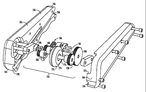
The handle assembly 150 is shown in greater detail in Figures 4, 5A, and
5B. The handle assembly 150 includes a handle housing 152 is designed to
easily and comfortably fit into a practitioners hand, and to be easily
manipulated
with single hand use. In one option, the handle housing 152 are formed of a
first portion 154 and a second portion 156 that are coupled together, for
example, by one or more threaded fasteners. Other devices and/or methods for
coupling the first and second portions 154, 156 of the handle housing 152 are
suitable as well, such as, but not limited to, adhesive, welding, snap-fit,
etc.
The handle housing 152 includes a handle lumen 158 therein. The
handle lumen 158 is aligned with the delivery lumen of the catheter body 110
(Figure 2), and the handle lumen 158 extends from a first end 160 to a second
end 162 of the housing. A medical instrument, such as, but not limited to, a
guidewire, a lead, an ablating device, etc., is disposed through the second
end
162 of the housing 152 and through the delivery lumen of the catheter body 110
(Figure 2). In one option, a valve 130 is coupled with the delivery lumen of
the
catheter body 110 (Figure 2). The valve 130 provides further prevention of
5
CA 02490752 2004-12-21
WO 2004/000405 PCT/US2003/019769
Attorney Docket No. 905.032W01
inadvertent fluid leakage from the delivery lumen. In another option, a side
port
132 is coupled with the valve 130, which allows for the valve 130 to be
flushed
with fluids. The side port 132 is disposed through a portion of the handle
assembly 150, for example, through an opening 134, allowing access to the side
port 132 by a physician or medical technician. It should be noted that the
valve
130 and/or the side port 132 can be combined with any of the above or below
discussed embodiments.
The handle assembly 150 includes therein the actuator assembly 170 that
moves the pull wire 120 (Figure 2), and deflects the distal end 104 (Figure 2)
of
the catheter body 110 (Figure 2). Refernng to Figure SA, the actuator assembly
170 includes an actuator 172 disposed through a slot 173 of the handle housing
152. The actuator 172 is manipulatable by an operator to deflect the distal
end
104. In one option, the actuator 172 includes a wheel member 174 that is
easily
manipulated by the thumb in a rolling motion. The rotational input from the
thumb is transferred into linear movement to provide the linear stroke for the
pullwire on the proximal end, as further described below.
The following is one example of how to construct the steering assembly.
It should be noted that several variations exist, including more simplified
gearing configurations. In one option, the actuator 172 is coupled with a
first
axle 175 that rotates about a first actuator axis 176. Also coupled with the
first
axle 175 is a first gear 178 that meshes with a second gear 180. The second
gear 180 is coupled with a second axle 181 that rotates about a second axis
182.
A third gear 184, in one option, is disposed on the opposite side of the
actuator 172 as the first gear 178. The third gear 184 is fixed with the first
axle
175 and is adapted to mesh with a static component, such as locking paw 186,
when the actuator assembly 170 has been placed in a locked mode. The locking
paw 186 is affixed to the handle portion, for example, with threaded
fasteners.
In one option, the locking paw 186 includes, for example, teeth integrally
formed within the handle housing. A biasing member 202, such as, but not
limited to, a spring, a living hinge, a spring steel member, biases the third
gear
184 into meshing with the locking paw 186 when no force is placed on the
6
CA 02490752 2004-12-21
WO 2004/000405 PCT/US2003/019769
Attorney Docket No. 905.032W01
actuator 172. It should be noted that one or more biasing members 202 can be
used to bias the actuator 172 into a locked position.
The locking paw 186 mechanically prevents the actuator 172 from
moving until it is moved out of the locked mode. When the actuator assembly
170 is placed in the locked mode, as shown in Figure 6, the actuator 172 is
mechanically locked from moving, which also locks the pull wire from
moving. This is particularly advantageous over conventional designs, or
designs that prevent movement by friction, since the physician can be
confident
that the deflection of the distal end will not be inadvertently modified.
Furthermore, when the distal end is in a highly articulated position, the
distal
end will not succumb to change when the physician releases the steering
mechanism, for example, to introduce other instruments through the catheter
assembly.
Figure SB illustrates another example of the gearing mechanism for the
catheter assembly. The actuator 172 is coupled with a series of gears 138
that,
in one option, are assembled in a linear fashion. The series of gears 138 are
each coupled with an axle 142, about which each gear 140 rotates. In one
option, the axle 142 includes a projection 144, such as a post, that extends
from
an inner surface 146 of the handle housing 152. Alternatively, or in
combination, the axle 142 is disposed through or made integral with the gear
140, and the axle 142 is disposed within a recess formed within the handle
housing 152. The axle 142 can be coupled directly or indirectly with the
handle
housing 152. The series of gears 138 cooperatively operate as is shown in
Figure SB, where a first gear 146 is coupled with the actuator 172. Rotation
of
the actuator 172 causes rotation of the series of gears 138, and linear
movement
of the rack 194, as further discussed below. Locking and unlocking of the
series
of gears 138 can be achieved using the various embodiments discussed above
and below, and shown in the Figures.
When the actuator assembly 170 is affirmatively placed in an
operational mode, as shown in Figure 7, the third gear 184, or the series of
gears
138, is free to rotate, allowing the actuator 172 to freely rotate. In one
option, to
7
CA 02490752 2004-12-21
WO 2004/000405 PCT/US2003/019769
Attorney Docket No. 905.032W01
place the actuator assembly 170 in an operational mode, the actuator 172 is
depressed to a position at least partially within the handle housing 152. As
the
actuator 172 is depressed, the user overcomes the bias from the biasing
member, and the third gear 184 disengages from the locking paw 186. In
another option, a trigger 173 (Figure SB) that is remote from the actuator 172
is
used to place the actuator assembly 170 in operational mode. In one option, as
the actuator assembly 170 is placed in operational mode, an audible click can
be
heard, thereby notifying the physician that the assembly is affirmatively in
the
operational mode. Other options for indicating to the physician that the
status
of operation has changed are possible as well. For example, a tactile click
can
be felt on the actuator 172, or a visual indicator can be provided, as further
discussed below.
During operation, when the actuator assembly 170 is in the operation
mode, the actuator 172 drives one or more gears 190, including a driving gear
192. The driving gear 192 drives a rack 194 that is coupled with the pull wire
120 (Figures 2 and 6). As the actuator 172 is moved, for example, rotated, the
rack 194 is moved linearly and thereby pulls the pull wire 120. The linear
movement of the rack 194 in combination with the pull wire 120 assists in
preventing unnecessary fatigue being placed on the pull wire 120, for example
by wrapping and unwrapping the pull wire 120 around a rotating member.
As the pull wire 120 is moved, this pulls on the pull wire anchor, and the
distal end of the catheter body is deflected into position as desired by the
physician. In one option, an indicator is associated with the movement or
deflection of the catheter body, such that feedback is provided while the body
is
being moved. When in place or in a proper position, the physician releases the
actuator 172, allowing the actuator assembly 170 to be locked in place, and
further movement of the distal end is affirmatively prevented. In one option,
as
the physician releases the actuator 172, an audible click can be heard. For
example, the meshing of the gears can be configured to cause an audible click.
Other options for indicating to the physician that the status of operation has
changed are possible as well. For example, a tactile click can be felt on the
8
CA 02490752 2004-12-21
WO 2004/000405 PCT/US2003/019769
Attorney Docket No. 905.032W01
actuator 172, or a visual indicator can be provided when the actuator 172 is
placed in the locked mode. In another option, the tactile click is caused by
friction or rubbing of two or more components. The notice to the physician, in
another option, involves an audible sound, or a tactile or visual indicator
while
the actuator 172 is being moved to manipulate the flexible element. For
instance, in one option, while the actuator 172 is moved by the physician, a
projection or finger would mesh with indentations or projections on the
actuator
172, allowing the physician to feel or hear a clicking sound as the actuator
172
is rotated or moved. This can be done exclusive to the audible click or
tactile
click or visual indicator, or it can enhance these features. It should be
noted that
other indicators can be incorporated herein, and/or incorporated with the
various
embodiments discussed/shown above and below.
In another embodiment, a method comprises manipulating a catheter
assembly, the catheter assembly including a handle assembly, a catheter body
controllable by a flexible element coupled with the handle assembly. An
actuator member is coupled with the flexible element, where movement of the
actuator member provides for movement of the flexible element, and the
actuator has a locked mode and an operational mode. The actuator and the
flexible element are not movable relative to the handle assembly when the
actuator is in the locked mode. The method further includes moving the
actuator and unlocking the actuator, and placing the actuator in an
operational
mode. In addition, the method includes steering the catheter assembly
including
moving the actuator and deflecting the distal end.
Several options for the method are as follows. For instance, in one
option, the method further includes releasing the actuator and locking
movement of the flexible element relative to the handle assembly. In another
option, the method further includes providing feedback to the user when the
actuator is placed in the operational mode and/or the locked mode. In yet
another option, placing the actuator in the locked mode includes enmeshing a
gear coupled with the actuator with a static component. Optionally, moving the
actuator includes depressing the actuator within the handle assembly.
9
CA 02490752 2004-12-21
WO 2004/000405 PCT/US2003/019769
Attorney Docket No. 905.032W01
Advantageously, the above-described deflectable catheter allows for
increased control of the distal deflectable catheter end. The locking
mechanism
provides for accurate locking of the deflectable end in a certain position,
allowing the physician increased control during the placement of the catheter
within a patient. Furthermore, the indicator informs the physician when the
deflectable catheter assembly has been placed in a locked and/or operational
mode.
The deflectable catheter allows for single handed precise movement of
the distal tip, and allows for locking a position in place easily. The lock
further
assists in preventing inadvertent movement of the distal tip, for example,
during
an ablation procedure. Furthermore, with the above-described design, the
distal
end can be easily configured to have different radius of curvature by varying
the
stroke length. Another option is to vary the input/output of the actuator by
modifying the gear ratio. A further benefit of the device is the feedback
1 S provided when the lock is released, for example, the audible click. This
affirmatively informs the physician when the steering mechanism is placed in
the operational mode and/or the locked mode.
It is to be understood that the above description is intended to be
illustrative, and not restrictive. Many other embodiments will be apparent to
those of skill in the art upon reading and understanding the above
description.
It should be noted that embodiments discussed in different portions of the
description or referred to in different drawings can be combined to form
additional embodiments of the present invention. The scope of the invention
should, therefore, be determined with reference to the appended claims, along
with the full scope of equivalents to which such claims are entitled.