Note: Descriptions are shown in the official language in which they were submitted.
CA 02490839 2000-03-20
WO 01110588 PCT/NLOO/00184
APPARATUS FOR DEPLOYING A LOAD TO AN UNDERWATER TARGET POSITION WITH
ENHANCED ACCURACY AND A METHOD TO CONTROL SUCH APPARATUS
The present invention relates to an apparatus for deploying an object to an
underwater target position, the apparatus being provided with a beacon to
transmit
acoustic rays and a plurality of thrusters to control positioning of the
apparatus with
respect to the underwater target position.
Such an apparatus is known from WO 99/61307.
The prior art apparatus is used for deploying and/or recovering loads up to
1000
tons or more on the seabed at great depths, for instance, up to 3,000 meter or
more. During
deployment, the apparatus is controlled by controlling equipment on board of a
vessel
floating on the sea surface. The controlling equipment needs to know the exact
location of
the apparatus as accurate as possible. To that end, the beacon on board of the
apparatus
transmits acoustic rays through the sea water to the vessel. An appropriate
acoustic
receiver receives these acoustic rays and convtrts them into electrical
signals used to
calculate the position of the apparatus with respect to the vessel.
However, it is found that with increasing depth of the apparatus below the sea
water the accuracy of the location measurement decreases due to bending of the
acoustic
rays in the sea water.
The object of the invention is therefore to further enhance the accuracy of
the
location measurement of such an apparatus during use in sea water or any other
fluid
Moreover, such location measurement is needed on-line (real-time).
To obtain this object, the apparatus as defined at the outset is
characteriz,ed in that it
is provided with a sound velocity meter to measure velocity of sound in a
fluid
surrounding said apparatus. Thus, the velocity of sound at a certain location
in the fluid
can be continuously measured and used to update a sound velocity profile,
i.e., data as to
the sound velocity as a function of depth in the fluid. From these data, local
bending of the
acoustic rays can be determined on-line (real-time). So far, such on-line
determination has
not been possible. This allows corrections of location measurements in real-
time.
In a preferred embodiment, the thrusters comprise a first set of thrusters
arranged
to provide a torque control function and a second set of thrusters arranged to
provide at
least a translation function, each thruster of the second set of thrusters
being provided
with a rotary actuator.
CA 02490839 2000-03-20
WO 01/70568 PC'7/NL00l00184
2
This is a very advantageous embodiment Only two thnusters are necessary to
prevent any undesired rotation of the apparatus attached to the load during
deployment
thus avoiding all problems related to twisting and turning of hoist wires
carrying the load,
as already explained in WO 99161307. Moreover, only two rotatable duusters are
needed
to control positioning of the apparatus with its load aitached to it to the
desired horizontal
coordinates. Thus, prior to lowering the load with the apparatus the apparatus
can move
the load to the desired horizontal coordinates and when these coordinates have
been
maehed the hoist wire(s) can lower the load to its desired location on the
seabed while the
thnmers keep the load on the desired coordus3tes and prevent any undesired
rotation of
the load. Only when the desired target position on the seabed is reached a
possible rotation
of the load to a desired orientation need be carried out by the thnisters
dedicated to the
torque control.
It is observed that rotatable thtusters on an underwater apparatus for
deploying
loads to a desired position are lcaown from US-A-5,898,746.
The apperatus is preferably provided with load cells to measure weight of the
load
attaehed to the apparatas. When the load is put on the seabed by this weight
suddenly
decreases. Thus, a signal indicating that the weight of the load suddenly
deccee.ses can be
used to determine when the apparatus may be detached from the load.
The invention also relates to a pmcessing arrangement airanged to drive an
appa-
zatus for deploying an object to an underwater target position, the apparatus
being pro-
vided with a beacon to transniit acoustic rays, a plurality of thrusters to
control posi-
tioning of the apparatas with respect to the underwater target position, and a
sound
velocity meter to measure velocity of sound in a fluid surrounding the
apparatus, the proc-
essing arrangement being provided with an acoustic receiver to receive the
acoustic rays,
the processing arrangement is arranged to use data derived from the acoustic
rays in a
calculation to determine the position of the apparatus characterized in that
the processing
arrangement is arranged to receive online sound velocity meter data from the
sound
velocity meter to detemine a sound velocity profile in the fluid and to
calculate from the
sound velocity profile bending of the acoustic rays transmitted by the
apparatus through
the fluid and to use this in the calculation to determine the position of the
apparatus in
real-time.
Such a processing arrangement is able to control driving of said apparatus to
a
desired location in a desired orientation with very high accuracy, even at
great depth under
CA 02490839 2000-03-20
WO 01/70568 PCT/NL00/00184
3
water. While the apparatus with its load is lowered, the processing anangement
constantly
receives sound velocity data and determines a sound velocity profile
comprising sound
velocity data from the water surface to the depth of the apparatus. The
processing
arrangement uses these data to detennine acoustic ray bending as a function of
the depth
in the water and thus to correct any position calculation of the apparatau.
Such a processing arrangement may be on board of a vessel floating on the
water
surface. However, it is to be understood that part of the fiu-ctionality of
determining the
sound velocity profile and calculating the acoustic ray bending may be carried
out by one
or more processors located elsewhere, even on board of the apparatus itself.
Preferably, a further sound velocity meter is provided just below the water
surface
to provide actual data regarding any ray bending in the water surface layers
and thus to
further correct any position calculation of the apparatus.
Reception of the acoustic rays transmitted by the apparatus is preferably
performed
by an acoustic array attached to the hull of the vessel.
In a very preferred embodiment, the vessel, the acoustic array and the
apparatus are
all provided with a distinct gyrocompass measuring respective heaves, rolls
and pitches.
Output data from these gyrocompasses are used to further increase accuracy of
the
position measurement of the apparatus.
The invention also relates to a system comprising such a vessel and an
apparatus
together.
The invention also relates to a method of driving an apparatus for deploying
an
object to an underwater target position, the apparatus being provided with a
beacon to
transmit acoustic rays, a plurality of thrusters to control positioning of the
apparatus
with respect to the underwater target position, and a sound velocity meter to
measure
velocity of sound in a fluid surrounding the apparatus, the method comprising
the steps of:
= receiving the acoustic rays,
= using data derived from the acoustic rays in a calculation to determine the
position of
the apparatus
characterized by the steps of:
= receiving sound velocity meter data from the sound velocity meter and
determining a
sound velocity profile in the fluid, and
CA 02490839 2000-03-20
wo 01n0568 PCT/N1AO/00184
4
= calculating from the sound velocity profile bending of the acoustic rays
transmitted
by the apparatus through the fluid and to use this in the calculation to
determine the
position of the apparatus.
This method may be entirely controIled by a suitable computer program after
being
loaded by the processing arrangement. Therefon:, the invention also relates to
a computer
program product comprising data and instructions that after being loaded by a
processing
arrangement provides said anangement with the capacity to carry out a method
as defined
above.
Also a data carrier provided with such a computer program product is claimed.
Below, the invention will be explained in detail with reference being made to
the
drawings. The drawings are only intended to illustrate the invention and not
to limit its
scope which is only defined by the appended claims.
Figure 1 shows a schematic overview of a FPSO (floating, production, storage
and
oifloading system) dedicated to offshore petrochemical recoveries.
Figure 2 shows a crane vessel according to the prior art and displaying a load
rigged to the crane block with relatively long wire ropes whereby it is
possible to see that
the control of the load is virtually impossible at great depth.
Figure 3 shows a crane vessel and an underwater system for deploying and/or
recovering a load to and/or from the seabed according to the prior art.
Figure 4 shows a detailed overview of a possible embodiment of the underwater
system.
Figure 4a shows a detailed overview of one of the rotatable thrusters.
Figure 5 shows the underwater system viewed from above.
Figures 6a and 6b schematically show the underside of the main module with
some
detectors.
Figure 7a shows a schematic block diagram of the electronic equipment on board
of the vessel.
Figure 7b shows a schematic block diagram of the electronie equipment related
to
an acoustic array and related to the underwater system.
Figure 8 shows the definition of three different coordinate systems used
during
driving the underwater system to its target position.
Description of the greferred embodiment
CA 02490839 2000-03-20
WO 01!70568 PCT/NL00/00184
With r+eference to figure 1, the layout presents a FPSO I with swivel
production
stack l 1 from which risers 2 depart, said risers connecting to their riser
bases 3 at the
seabed 4. During production lifetime, it is paramount for the FPSO I to remain
within an
allowable dynamic excursion range and therefor the FPSO I is moored to the
seabed 4 by
5 means of mooring legs 5 which are held by anchors 6, or alternatively by
piles.
Exploitation of oil or gas by means of a production vessel 1, requires that
several
relatively heavy objects be positioned at the seabed 4 with a high accuracy.
To secure an appropriate and safe anchoring by means of the mooring legs 5, it
is
required that these mooring legs 5 have approximately the same length. In
practice for this
application anchors can be used with a weight of 50 ton and more, which are
placed at the
seabed 4 with an accuracy to within several meters. Moreover not only is the
anchor 6
itself very heavy, but the mooring leg attached to the anchor 6 has a weight
that equals
several times the weight of the anchor 6 itself.
Also for other objects like the "templates", "gravity riser bases",
"production
manifolds" etceteras applies that these objects have to be put on the seabed 4
with
relatively high accuracy.
The objects that are shown in figure 1 that are required for exploiting the
oil and
gas at sea and that have to be put on a seabed, are not only very heavy, but
very expensive
as well.
Figure 2 shows a vessel 20, according to the prior art, having hoisting means
thereon, like a crane 21. The crane 21 is provided with a hoisting wire 22, by
means of
which an object or a load 4 can be put on the seabed 5. In order to position
the load 23 it is
necessary to move the surface support together with the crane 21.
The result will be that, at one given time, the load 23 inertia will be
overcome but
due to the load 23 acceleration, an uncontrollable situation will occur,
whereby the target
area will be overshot. Because of the fact that the hoisting wire 22 and the
load 4 are
susceptible to influences like the sea current, the load 23 will not move
straight
downward, when the hoisting wire 22 is being lowered. Also the heave, roll and
pitch of
the vessel 20 will have a negative influence on the accuracy that can be
achieved.
Figure 3 shows a crane vessel 40 provided with an underwater apparatus or
system
50 for deploying a load 43 on the seabed 4. The vessel 40 comprises first
hoist means, for
example a winch 41, provided with a first hoist wire 42. By means of this
hoist wire 42 the
load 43, for instance a template can be deployed and placed at the bottom of
the sea.
CA 02490839 2000-03-20
WO 01/70568 PCT/NLOO/00184
6
As mentioned above, the exploitation of oil and gas fields using a floating
production platform requires that several heavy objects must be placed at the
seabed 4,
moreover, these objects have to be placed on the seabed 4 with a very high
accuracy.
Because of the fact that nowadays the exploitation has to be done at
increasing depths up
to 3000 m and more, achieving the required accuracy is getting harder. E.g.,
one of the
problems to be solved is the possible rotation of the load 43 carried by hoist
wire 42.
In order to control the position of the load 43 when deploying it and in order
to be
able to position the load 43 on the seabed 4 within the required accuracy, the
apparatus or
system 50 has been secured to the lifting wire 42. A preferred embodiment of
the system
50 will be described with reference to figures 4, 5, 6a and 6b.
The system 50 may engage the end of the lifting wire 42. Altematively, the
system
50 may directly engage the load 43 itself. The system 50 comprises a first or
main-module
51, provided with drive means such as thnaters 56(i), i= 1, 2, 3, ...[, I
being an integer
(figures 4 and 5). The system further comprises a second or counter module 52.
This
counter-module 52 is also provided with thrusters 56(i). In use the thrusters
of the main-
module 51 and of the counter-module 52 will be positioned at opposite sides of
the lifting
wire 42.
The system 50 is coupled to the vessel 40 by means of a second lifting wire
45,
which can be operated using second hoist means, for instance a second winch
44. The
second hoist wire 45 is, for instance, set overboard by means of an A-frame
49. The
second winch 44 and the second hoist wire 45 will be normally lighter than the
first hoist
means 48 and the primary hoist wire 42, respectively. The system 50 is further
connected
to the vessel 40 by means of an umbilical 46. This umbiGcal 46 can be attached
to the
hoist wire 45 or can be lowered from a tertiary winch 47 separately. The
electricity wiring
for providing power to the system 50, as well as electrical wiring or optical
fibers are for
instance accommodated in the umbilical. In the system 50 usually means are
provided to
convert the electrical power into hydraulic power. The hydraulic power
consequently will
be used for controlling i.a. the thrusters 56(i) and auxiliary tooling
amenities.
Since lately the work is being done at an increasing depths, twisting and
tuming of
the loads 43 and long hoist wires 42 is becoming a bigger problem still. Since
heavy loads
43 are attached at the underside of the hoist wire 42, such twisting and
tuming can impel a
relatively large wear on the hoist wires, so severe damage can occur at the
hoist wires.
This wear can be so severe that a hoist wire 42 will break and the load 43
will be lost.
CA 02490839 2000-03-20
WO 01170568 PCf/NL00100184
7
Another problem is that because of enormous twists in the wires, the wires at
tbe vessel
can run out of the sheaves.
Because of the fact that the thrusters 56(i) of the main-module 51 and of the
counter-module 52, respectively, are positioned at opposite sides of the
lifting wire 42, a
counter-torque can be exerted at the hoist wire 42 in both directions. In this
way by means
of the system an anti-twist device is formed. In order to improve the
abilities of this anti-
twist device, preferably, the distance between the main-module 51 and the
counter-module
52 can be altered.
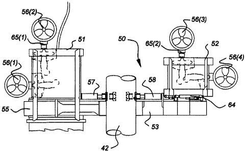
Figure 4 shows a detailed overview of a possible embodiment of the system 50
for
deploying a load 43 on the seabed 4. Figure 5 shows the system according to
figure 4,
from above.
The system 50 comprises the main-module 51, the counter-module 52 and an arm
53. The emt 53 can be detached from the main-module 51. That means that the
main-
module 51 can also be used separately, as a modular system. The arm 53 is
provided with
a recess 54. On opposite sides of this recess 54 two jacks 57, 58 are
provided, at least one
of which can be moved relative to the other. In between the end surfaces of
these jacks 57,
58 an object, such as a crane-block of load 43, can be clamped. In order to
improve the
contact between the jacks 57, 58 and the object, the respective ends of the
jacks are
accommodated with clamping shoes lined with a friction element, from a high
friction
material such as dedicated rubber.
In use, the thrusters 56(i) can be used to position the system 50 relative to
a target
area on the seabed 4. The throsters 56(i) can be actuated from a first
position mainly inside
the system 50, to a position in which the thrusters projects out of the system
50. The two
upper thrusters 56(2), 56(3) are rotatable with respect to the underwater
system 50. They
are, for instance, installed on respective rotary actuators 65(1), 65(2). The
purpose thereof
will be explained later. Thruster 56(2) has been shown on an enlarged scale in
figure 4a.
In figure 5 it is shown that there are two positions 61, 62 on top of the main-
module 51 to connect the main module to the second lifting wire 45 andlor to
the
umbilical 46. When the main-module 51 is used separately position 61 can be
used. The
main-module 61 will be balanced when the module 61 is deployed, both in the
air and
underwater.
When the system 50 is used, the connection between the vesse140 and the system
50 will be fixed in position 62 in order to keep the system in balance, both
in the air and
CA 02490839 2000-03-20
WO 01/70568 PCT/NLAO/00184
8
underwater. To improve the balance of the system, an auxiliary counterweight
55 can be
secured to the system 50.
ln use, the apparatus 50 will not have any buoyancy. In order to improve the
movability of the system under water, the arm 53 is provided with holes 59, in
order to
avoid structural damage due to an increasing pressure while being lowered and
to ensure
quick drainage during the recovery phase.
As mentioned above, it is advantageous when the counter-module 52 can be moved
relative to the main-module 51. This can be accomplished by using jacks 64a.
The module 51 comprises an outer frame and an inner frame (both not shown).
The
inner frame preferably is cylinder-shaped. By connecting the outer frame to
the inner
frame, a very strong construction can be accomplished. The strength of the
construction is
necessary in order to avoid premature fatigue in the system.
The module 51 is, for instance, partly made of high-tensile steel and thereby
designed to be used as integral part of either the first 42 or second hoist
wire 45. This
means that the top side of the module 51 will be connected to a first part of
the hoist wire
45, and that the underside of the module 51 will be connected to a second part
of the hoist
wire 45, or the underside of the module 51 will be attached directly to the
load. In this way
the load on the hoist wire will be transfen-ed through the module 51.
As mentioned before, the module 51 is provided with a thruster drive 270 for
converting electrical power, delivered through the umbilical 46, into
hydraulic power.
This thruster drive 270 may comprise motors, a pump, a manifold and a
hydraulic
reservoir. Such converting means are known to persons skilled in the art and
need no
further explanation here. In order to communicate relevant data as to its
position, both
absolute and relative to other objects, to the control system and/or an
operator on board of
the vessel 40, the module 51 further comprises sensor means and control means
that will
be explained in detail below. The module 51 is equipped with a sensor junction
box.
Moreover, the module 51 comprises light-sources 87, a gyrocompass 256
including heave,
roll and pitch sensors, a pan and tilt color camera 97, a USBL responder 255
including a
digiquartz depth sensor 253, a sound velocity meter 258, and a sonardyne mini
Rovnav
264. At the underside of the module 51 are mounted on several platfonns light
sources 94,
a pan and S.l: T. camera 93, an altimeter 262, a Doppler log unit 266, and a
dual head
scanning sonar 260. They are installed there to have only clear sea water
below them, in
use. They are schematically shown in figures 6a and 6b. It is to be understood
that they
CA 02490839 2000-03-20
WO oln9568 PCT/NLOO/00184
9
may be located elsewhere, e.g., at the underside of module 52. Moreover, load
cells 268
are part of the system 51. All these components are schematically indicated in
figure 7b.
As mentioned above, the use of high resolution sonar equipment 260 together
with
a distance log, measured by Doppler log unit 266, is important to achieve the
required
accuracy, once the load has reached its intended depth. The sonar equipment
260 will be
used to detemiine the position with respect to at least one object positioned
at the seabed.
Using the distance log, it will then be possible to dissociate the positioning
activities from
the surface support, as well as from any other acoustic transponder devices
such as LBL
(Long Base Line) arrays (or other, e.g., USBL), while accuracy in the order of
centimeters
will be achieved within a large radius.
Figure 7a shows the electronic equipment 200 installed on the vesse140,
whereas
figure 7b shows deployable acoustic array 250 with velocity meter 248 and a
gyro
compass 252. Figure 7b also shows underwater electronic equipment 249
installed on
the underwater system 50.
The equipment shown in figure 7a comprises four processors: a navigation proc-
essor 202, acoustic processor 224, a sonar control processor 236, and a
thruster control
processor 240. The navigation processor 202 is interfaced to the other three
processors
224, 236, 240 for mutual communications and complementarity.
The navigation processor 202 is also interfaced to a surface positioning equip-
ment DGPS (Differential Global Positioning System) 204, a vessel gyrocompass
206,
four display units 208, 210, 212, 214, a printer unit 218, a keyboard 220, a
mouse 222,
and a fiber optic (de)multiplexer unit 244. If necessary, a video splitter 216
may be
provided to transmit one SVGA signal output of the navigation processor 202 to
two or
more display units. In figure 7a, display units 212, 214 are connected to the
navigation
processor 202 via video splitter 216.
The fiber optic (de)multiplexer unit 244 is also connected to the acoustic
proces-
sor 224, the sonar control processor 236, and the thruster control processor
240.
The acoustic processor 224 is connected to a command and control unit 226
which is connected to a keyboard 230, a mouse 232 and a display unit 228, all
together
forming a USBL surface unit 234.
The acoustic processor 224 is connected to deployable acoustic array 250 with
motion sensor unit 252 and velocity meter 248. In use, the acoustic array 250
is, pref-
erably, mounted 2.5 meters below the keel of vessel 40.
CA 02490839 2000-03-20
WO 01/70568 PCT/NL00/00184
The fiber optic (de)multiplexer unit 244 is connected to a further fiber optic
(de)multiplexer 246 installed on the underwater system 50. An optical fiber
intercon-
necting both fiber optic (de)multiplexers 244, 246 is preferably accommodated
in um-
bilica146 (figure 3).
5 The sonar control processor 236 is connected to a display unit 238. The
thruster
control processor 240 is connected to a display unit 242.
The underwater equipment 249 is shown in figure 7b in the form of a block dia-
gram. The USBL responder 255 with digiquartz depth sensor 253, a gyrocompass
with
motion sensors 256, (removable) sound velocity meter 258, a dual head scanning
sonar
10 260, altimeter 262, sonardyne mini Rovnav 264, Doppler log 266, load cells
268, and
thruster drive control 270 are all connected to the fiber optic
(de)multiplexer 246.
Moreover, figure 7b shows two beacons 272, 274 that can be installed on the
sea-
bed or on the load to be deployed (or on other structures already on the
seabed). These
beacons 272, 274 can, e.g., be interrogated by means of the sonardyne mini
Rovnav
264 (or equivalent equipment) to transmit acoustic signals back to the system
50 that
can be used by the system 50 itself to determine 'and measure distances and
orientations
relative to these beacons. Such an acoustic telemetry link results in very
high precision
relative position measurements. The number of such beacons is not limited to
the two
shown in figure 7b.
Functionality
The functions of the components shown in figures 7a and 7b are the following.
The navigation processor 202 is collccting the surface positioning equipment
data
(DGPS receivers, DC}PS corrections, vessel's gyrocompass and vessel's motion
sensors
204 and 206), in order to calculate and display the vessel's attitude and its
fixed offsets.
Via the fiber optic (de)multiplexers 244 and 246, the navigation processor 202
sends different settings to the navigation instruments of the system 50, i.e.,
Doppler log
266, altimeter 262, and gyrocompass and motion sensors 256. After setting up,
it
receives the data from those instruments, as well as, via the acoustic
processor 224, the
range/bearing and depth data of the system 50 to calculate and to display the
attitudes
and absolute coordinates of the system 50.
An integrated software in the navigation processor 202 has been developed, in-
cluding a dynamic positioning controller software able to work in manual or
automode
to decide the intended heading of the system 50 and to select between many way
points
CA 02490839 2000-03-20
wo olf7o56s PCT/NLOO/00154
11
and to carry out the intended positioning. Moreover, the operator on board of
the vessel
can input offsets to the selected way point, the offsets being input with XY
coordinates
relative to the heading of the system 50. There is another possibility to
select several
other types of sub-sea positioning devices via an arrangement of specifically
designed
windows on the screens (electronic pages) of the display units 208-214, to
stabilize and
filter the position. To ensure that the operator has as many tools as possible
to get the
optimal result, there is an other part in the software showing different
status of the sub-
sea instruments in use for the calculation of the position of the system 50 on-
line (real-
time).
Embarked gyrocompass 256 including heave, roll and pitch sensors 88 on board
of the system 50 provides data as to the exact attitudes of both the system 50
and the
load 43 to be installed on the sea bed. At the surface of the sea, in a
control van,
operators are able to check those attitudes on-line (real-time), during
descent but also
once the load 43 is laying on the sea bed for final verification.
The vessel gyrocompass 206, as well as the gyrocompass with motion sensors
252 installed on the acoustic array 250 that could be used for the same
functions, is
transmitting the vessel's heading to the navigation processor 202. The
navigation proc-
essor 202 will use this vessel's heading to calculate different offsets.
The display units 208, 210, 212, and 214, respectively, are arranged to
display
navigation settings, a view of the sea bed, a view of the surface, in the
control van for
the operators and another one on the vessel bridge for the marine department
operators.
The USBL command and control unit 226 consists of a personal computer pro-
viding control and configuration of the system and displaying the man-machine-
inter-
face for operator control.
The acoustic processor 224, preferably, consists of one VME rack which per-
fonms correlation process on received signals, corrections to bathy-
celerimetry and ves-
sel's attitude. Moreover, it calculates coordinates of any beacon used. The
acoustic
processor 224 is linked to the navigation processor 202 through Eternet.
The acoustic array 250 includes means for transmission and reception. The
acoustic array 250 can be used as a transducer to acoustically communicate
with one or
more beacons. Such a transducer mode is advantageous when the umbilical 46
fails and
is unable to transmit interrogation signals down to the system 50. Then,
acoustic inter-
rogation signals can be transmitted down by the transducer directly through
the sea
CA 02490839 2000-03-20
wo OU70568 PCT/NLOOI00184
12
water. In all other cases, the acoustic array 250 will be used in a reception
mode.
Reception is done with two orthogonal reception bases which measure distances
and
bearing angles of beacons relative to the acoustic array 250. Each reception
base in-
cludes two transducers. Each received signal is amplified, filtered and
transferred to the
acoustic processor 224 for digital sigaal processing.
The sound velocity meter 248 installed on the acoustic array 250 is updating
in
real-time the critical and unsettled sound velocity profile situated just
underneath the
vessel 40. This is of great importance since turbulences of the sea water
appear to be
very heavy in these layers just underneath the vessel 40.
The gyrocompass 252 is preferably used as motion sensor unit transmitting the
acoustic array attitude to the acoustic processor 224 in order to reetify data
as to the
position of the system 50 sub-sea.
In a preferred embodiment, the beacon 254 is working in a responder mode and
has the following characteristics:
- the triggering interrogation signal generated by the acoustic processor 224
is not
acoustic but electrical and is transmitted to the beacon 254 through the cable
link
between the vessel 40 and the system 50;
- interrogation frequencies are remotely controlled by an operator through the
man-
machine-interface.
As indicated above, the beacon 254 can also be used in a transponder mode.
Then, the beacon 254 is triggered by a surface acoustic signal transmitted by
the acous-
tic array 250 and then delivers acoustic reply signals to the acoustic array
250 through a
coded acoustic signal.
The digiquartz depth sensor 253 included in the beacon 254 allows transmitting
very accurate depth data of the system 50 to the acoustic processor 224. The
acoustic
processor 224 uses these data to improve the calculation of the sub-sea
positioning of
the system 50 and its load 43.
The sound velocity meter 258, mounted on the underwater system 50, is trans-
mitting data as to the velocity of sound in sea water at the depth of the
underwater sys-
tem 50 to the acoustic processor 224 during descent and recovery. The sound
velocity
data is used to update calculated sound velocity profiles in the sea water as
a function
of depth in real-time and to calculate acoustic ray bending from these
profiles as func-
CA 02490839 2000-03-20
WO 01/70568 PCT/NLOO/00184
13
tion of depth in the sea water and thus to correct calculations of the sub-sea
position of
the system 50.
The dual head scanning sonar 260 is used to measure ranges and bearings of the
system 50 to any man-made or natural target on the seabed and to output
corresponding
data as digital values to the navigation processor 202. The positions of such
man-made
or natural targets can either be predefined or the navigation system can
allocate coordi-
nates to each of the selected objects. After the objects have been given
coordinates,
they can be used as navigation references in a local coordinate system. This
results in
an accuracy of 0.1 meter in relative coordinates.
The altimeter 262 mounted on the system 50 is measuring the vertical distance
of
the underwater system 50 to the seabed and transmits output measuring data to
the
acoustic processor 224.
The Doppler log unit 266 provides data as to the value and direction of the
sea
water current at the depth of the underwater system 50. These data are used in
two
ways.
First of all, the data received from the Doppler log unit 266 and the
gyrocompass
with motion sensor 256 is used by the acoustic processor 224 to smooth on-line
(real-
time) the random noise related to using USBL. To obtain such a smoothing a
filter is
used, e.g., a Kalman filter, a Salomonsen filter, a Salomonsen light filter,
or any other
suitable filter in the main processor unit 224. Such filters are known to
persons skilled
in the art. A brief summary can be found in appendix A.
Secondly, the output data of the Doppler log unit 266 regarding current
strength,
current direction, together wit data regarding present and intended heading of
the
underwater system 50 are transmitt.ed to the thruster control processor 240
via the navi-
gation processor 202. Based on the intended direction the thruster drive
control 270
will be automatically controlled. Manual control may also be provided for.
In a very advantageous embodiment the Doppler log unit 266 (or any other suit-
able sensor) is used to measure temperature and/or salinity of the sea water
surrounding
the system 50. Data as to local temperature and/or salinity is transmitted to
the naviga-
tion processor 202 that calculates and updates temperature and/or salinity
profiles as a
function of depth in the sea water. These data are also used to determine
acoustic ray
bending through the sea water and, thus, to correct calculations of the
position of the
system 50.
CA 02490839 2000-03-20
WO 01nos68 PCTlN[AOl00184
14
The sonardyne mini Rovnav 264 is optional and may be used to provide relative
position of the system 50 to local beacons on the seabed as explained above.
For in-
stance, a Long Base Line (LBL) array may already be installed on the seabed
and used
for that purpose.
The load cells 268 are used to measure the weight of the load 43 as engaged by
the underwater system 50. When this weight decreases this is an indication
that the load
is now placed on the seabed (or other target position) and that the system 50
may be
detached from the load 43. Output data from the load cells is transmitted to
the naviga-
tion processor 202 through the (de)multiplexers 244, 246.
The thnister drive contro1270 is used to drive the thnisters 56(i) in order to
drive
the underwater system 50 to the desired position as will be explained in
detail below.
In figure 7a, four different processors 202, 224, 236 and 240 are shown to
carry out
the functionality of the system according to the invention. However, it is to
be understood
that the fimctionality of the system can, alternatively, be carried out by any
other suitable
number of cooperating processors, including one main frame computer, either in
parallel
or master slave arrangement. Even remotely located processors may be used.
There may
be provided a processor on board of the underwater system 50 for performing
some of the
functions.
The processors may have not shown memory components including hard disks,
Read Only Memory's (ROM), Electrically Erasable Programmable Read Only
Memory's
(EEPROM) and Random Access Memory's (RAM), etc. Not all of these memory types
need necessarily be provided.
Instead of or in addition to the keyboards 220, 230 and the mice 222, 232
other
input means known to persons sldlled in the art, like touch screens, may be
provided too.
Any communication within the entire arrangement shown may be wireless.
In figure 5, the situation is shown that the two upper thrasters 56(2) and
56(3) are
directed in an other direction than the thrusters 56(1) and 56(4). The
thrusters 56(2),
56(3) are mounted on rotary actuators 65(1), 65(2), which allow the thrusters
56(2),
56(3) to be vectored by turning them up to 360 . Preferably, the thrusters
56(2), 56(3)
can be independently controlled such that they may be directed each to a
different
direction.
To allow the thruster control processor 240 to accurately position the
underwater
system 50, a common coordinate system must be established between the
navigation
CA 02490839 2000-03-20
WO 01n0569 rcTnvwa00184
processor 202 and the thruster control processor 240. First of all, there is a
standard
coordinate system used by the navigation processor 202. However, two other
coordi-
nate reference systems are preferably established for the underwater system
50.
Figure 8 shows the three different coordinate systems. The coordinate system
5 related to the navigation processor 202 is indicated with "navigation grid".
This coordi-
nate system uses this "navigation grid" direction and its normal.
The thrusters 56(2), 56(3) are controlled to provide a driving force in a
direction
termed "thruster mean direction". This direction together with its normal
defines the
second coordinate system.
10 The third coordinate system is defined relative to the "system direction"
which is
defined as the direction perpendicular to a line interconnecting the thrusters
56(1),
56(4).
Now, an error in the path followed by the underwater system 50 can be defined
in
terms of an error vector that can be split into one component parallel to the
thruster
15 mean direction termed the "mean error" and a component normal to the
thruster mean
direction termed "normal mean error". Appropriate sensors on the underwater
system
50 will provide the navigation processor 202 with the thruster mean direction
and sys-
tem direction. From these data the navigation processor 202 will create a grid
as shown
in figure B.
The error is defined as the desired position DP minus the system position TP
such
that a vector RmEN is generated relative to the navigation grid reference,
i.e.:
DP-TP=R4aEN
Moreover.
OTN is the system orientation minus the navigation grid orientation,
Ow is the mean thruster orientation minus the system orientation.
Then:
DP - TP = RTEM, (DEM (DEN - (OTN + OMT)
Now R(DEM is known, the mean and the normal to the mean errors can be
calculated.
The two thrusters 56(1) and 56(4) are used to counteract the twisting forces
applied by the lifting cable 42, equipment drag and the rotational moment
induced by
the vectoring of positioning control. A control loop for the orientation
requires that the
navigation processor 202 is provided with the actual system orientation and
the desired
system orientation. The actual system orientation is measured by the
gyrocompass 256.
CA 02490839 2000-03-20
wo otnoS68 PCT/NLAO/00184
16
The desired orientation is manually input by an operator. From these two
orientations
the control loop in the navigation processor 202 computes an angular distance
between
the required orientation and the actual orientation as well as the direction
of rotation
required to move the system 50 accordingly. A simple control loop controlled
by the
tluuster control processor 240 then adjusts the power to the thrusters 56(1)
and 56(4) to
rotate the system 50 appropriately.
On power up of the system 50, both thrusters 56(2) and 56(3) will be,
preferably,
orientated such that the thruster mean direction is directed parallel to the
system direc-
tion. Then, the thrusters 56(2), 56(3) will be given a small vector angle
deviation from
the system direction to assist in positioning the system 50 in two planes. The
size of
this vector is, preferably, manually adjustable and may be needed to be
configured for
each different job in dependence on actual sea conditions. Once the thrusters
56(2) and
56(3) have been centered and vectored, a positioning loop can take over
control of the
system 50.
The positioning loop comprises two more phases.
In the first next phase, which is executed while the system 50 is still near
the sea
surFace, the sea current direction will be measured by the Doppler log unit
266. The sea
current direction will be transmitted to the navigation processor 202. Using
this direc-
tion, the thruster control processor 240 receiving proper commands from the
navigation
processor 202 will drive the rotary actuators 65(1), 65(2) such that the
thruster mean
direction substantially opposes the sea current direction. During this
rotation of the
rotary actuators 65(1), 65(2) none of thrusters 56(i) is powered. The system
direction
will be measured by the fiber optic gyrocompass 256. The depth is constantly
measured
by the digiquartz depth sensor 254 and the altitude by the altimeter 262. The
mean and
normal to the mean errors as calculated in accordance with the equations above
will
then be used by the positioning loop to apply power to the thnasters 56(2) and
56(3) to
drive the system 50 to the desired location.
During driving the system 50 with load 43 to the desired coordinates by means
of
thrusters 56(2), 56(3) the thrusters 56(1), 56(4) are used to counteract any
rotation of
the system 50 with its load 43. This provides for better control since,
especially for
heavy loads, rotation movements may result in other undesired movements of the
load,
which may be difficult to control. When the system 50 with its load is on the
desired
coordinates the load together with the system 50 is lowered by means of the
hoisting
CA 02490839 2000-03-20
WO 01170568 PCT/NL00/00184
17
wire 42. During descending the load 43, the load 43 is constantly controlled
by system
50 to keep it on the desired location without any rotation.
In a next phase, the system 50 is for instance approximately 200 m or less
from
the seabed 4. Then, the Doppler log unit 266 goes into a bottom track mode.
This
changes the operation into a more accurate and fast responding mode for the
final
approach of the target location on the seabed 4. Now, the Doppler log unit 266
and the
gyrocompass with motion sensors 256 are used to filter the random noise of the
USBL.
Once filtered, a good read out of the navigation data including an accurate
velocity of
the system 50 will make the position control loop both extremely rapid and
stable. A
very fine tuned control loop results in which control up to some centimeters
movement
is achieved. Now, the sonar unit 260 and the Doppler log unit 266 are used to
provide
information regarding the surroundings of the target point such that the load
43 can be
positioned on the right coordinates and in the right orientation. Then, a
rotation, if
necessary, may be applied to the load 43 by thrusters 56(1), 56(4) as
controlled by
thruster control processor 240.
Two control loops are provided for the thrusters 56(2), 56(3): a mean error
con-
trol loop and a further control loop to reduce the normal mean error.
The mean error control loop will adjust the power equally to both thrusters
56(2),
56(3) so as to reduce the mean enror. As the system 50 reaches the target
coordinates
the driving power to the thrusters 56(2), 56(3) will be reduced to such a
level that the
system 50 is able to maintain its position in the sea current. In other words,
initially, the
driving power was set at a level that was proportional to the mean error.
However, as
the system 50 moves closer to the target coordinates the control loop will
slowly reduce
the driving power applied to the thrusters 56(2), 56(3). As the system 50
reaches the
target coordinates an equilibrium will be reached where the driving power to
the thrust-
ers 56(2), 56(3) counteracts the strength of the sea current. The mean error
control loop
provides equal power with equal sign to both thrusters 56(2), 56(3).
A further control loop is applied to reduce the nonnal mean error. This
fiuther
control loop adjusts the individual power applied to the thrusters 56(2),
56(3) such that
a movement perpendicular to the sea current is generated. The further control
loop
applies equal power of opposite sign to both thrusters 56(2), 56(3) to this
effect. The
power applied to the thrusters 56(2), 56(3) in order to reduce the normal mean
error,
preferably, reduces linearly to zero as the system 50 moves to the target
coordinates. At
CA 02490839 2000-03-20
wo olnos68 PCT1NL00/00184
18
the point where the normal to the mean error reaches zero and assuming that
the sea
current direction has not changed, the system 50 will exactly be located above
the tar-
get position on the sea bed 4 and the thrusters 56(2), 56(3) are powered to
keep the
system 50 on the correct coordinates and to correct for the sea current.
If the sea current direction changes the control loops referred to above will
be
required to adjust the power applied to the thrusters and ultimately to change
the sys-
tem direction. As the new current direction acts upon the system 50, the
normal mean
enror will start to increase as the system 50 is moved from the target
coordinates. To
overcome this effect, the size of the normal mean error will again be
controlled to
reduce to zero. The system direction is changed such that the sea current or
natural drift
of the system 50 is counteracted.
The direction of rotation of the rotary actuators 65(1), 65(2) will be defmed
by
the sign of the normal mean error. To reduce the time required to slew the
rotary
actuators 65(1), 65(2) to the required position, an algorithm will be used by
the thruster
control processor 240 to determine the shortest route to the required
orientation.
It is envisaged that manual control by means of, for instance, a joystick (not
shown) connected to the navigation processor 202 is also amanged.
During the positioning of the system 50 a velocity control is also,
preferably,
applied. Preferably, the closer is the system 50 to the coordinates of the
target, the
slower will be the velocity of the system 50. For instance, when the distance
between
the system 50 and the target is more than a predetermined first threshold
value, the
tluusters are controlled to provide the system 50 with a maximum velocity.
Between
this first threshold value and a second threshold value of the distance to the
target coor-
dinates, the second threshold value being lower than the first threshold
value, a linearly
decreasing velocity profile is used. Within a distance smaller than the second
threshold
value the system is kept on a velocity of substantially zero.
USBL measurement
The USBL measurement principle is based on an accurate phase measurement
between two transducers. In one embodiment, a combination of short base line
(SBL)
and ultra short base line (USBL) is used which enables to use a large distance
between
transducers without any phase ambiguity. For an USBL, the accuracy depends on
the
signal to noise ratio and the distance between the transducers (like in an
interferometry
CA 02490839 2000-03-20
WO 01/70568 PCT/NL00/00184
19
method). Then, the trade-off is for frequency which is limited by the range
and hydro-
dynamic part in terms of dimensions.
Ambiguity is calculated by using an SBL measurement combined with correla-
tion data processing. The signal-to-noise ratio is improved by use of such
correlation
processing. The following expression defines the general accuracy for a USBL:
ae = K
L sl~ cos S
noise
where:
ve : Angular standard deviation
L : transducer distance
X : wavelength
0 : bearing angle
The expression given above indicates that the accuracy is improved by
increasing
the transducer distance L, i.e., by increasing the array. Moreover, a higher
frequency
results in a better accuracy. Hydrodynamic aspects and phase ambiguity reduce
these
parameters. Signal-to-noise ratio is increased by using correlation data
processing.
To optimize range and accuracy, a frequency of 16 kHz is preferably used for
phase meter measurements. A correlation process enables to increase the
distance range
while keeping a narrow pulse length for multipath discrimination.
For ambiguity phase measurements, the system operates in SBL to determine a
range sector and in USBL within the sector to achieve the best accuracy.
The range may be increased beyond 8000 m by using a rather low frequency.
CA 02490839 2000-03-20
WO 01/70568 PCT/NLOO/00184
Appendix A
Kalman fdter
The Kalman filter is probably the most well-known technique in the offshore in-
5 dustry. It gives a fast filtering method based on comparison towards
predicted values,
which are calculated on basis of the latest history. We will not go into
details about
Kalman filtering, but refer to, e.g., "Kalman Filtering - Theory and
Practice", by M.S.
Grewal and A.P. Andrews Prentice Hall (ISBN 0-13-211335-X).
The position track can be combined with the velocity data (Doppler log), each
10 point will be improved on basis of the neighboring points, the distance in
time and the
actual speed. The weight between Kalman value and the velocity improved is
decided
by the Doppler efficiency coefficient: higher values will take speed more into
consid-
eration.
15 Advantage: Disadvantage:
It's fairly fast Rather 'un-smooth' result
Can be improved with speed Not the best combination of speed
and position
Simple filter
20 The Simple filter runs through all positions, and calculates a smooth curve
giving
a minimum squared error, i.e. a kind of Least Square Fit line
Advantage: Disadvantage:
It's fast No Doppler-log data is used
The result is smooth Does not like curved tracks
Salomonsen filter
The Salomonsen filter, which is named after the Danish mathematician Hans
Anton Salomonsen, Professor and phD at University of Aarhus, is a highly
integrated
filter. It takes advantage of the short-term stability of the Doppler track
and combines it
with the long-term robustness of the position track.
Description
CA 02490839 2000-03-20
wo 01/70568 PCT/NLOOIoO184
21
The filter is used in a situation where we have time tacked position data
along a
track as well as Doppler data. The Doppler Data are usually very precise but
do not
give any information about the absolute positions. On the other hand the
position data
are absolute positions but they are usually not very precise.
The filter combines the two sets of data to produce a precise track with
absolute posi-
tions. This is done as follows.
1. The Doppler data are used to constract the shape of the track, i.e. a track
formed as
a cubic spine.
2. Beginning at the origin (0, 0) and with velocities as defined by the
Doppler data.
3. Then the position data are used to position the track correctly. The track
is trans-
lated, rotated, and stretched/compressed linearly to fit the position data as
well as
possible using least squares techniques.
4. It will mainly be a translation. However, the other modifications serve to
correct for
possible systematic errors in the Doppler data.
1S
The fact that the position data are used only to make the modifications in 2
means
that the position data are subject to considerable averaging. This reduces the
uncer-
tainty of the position measurements. Thus, if there are many position data the
absolute
position of the track should be expected to be much more precise than each
single posi-
tion measurement.
IiA. Salomonsen
Mathematical description
The algorithm is divided into five steps:
Step 1:
Calculate accelerations for each point
1 /2 hk+1(X 1 "+Xk+l ")=Xk+1'-Xk'
Where
hk = tk-tk-l
tk = timestamp for speed measurement
Xk'= speed measurement at tk
Xk"= calculated acceleration at tk
CA 02490839 2000-03-20
WO O1ROs68 PCT/NL00/00184
22
Step 2:
Calculate next position based on acceleration and speed, and previous
calculated posi-
tion (based on previous speed measurements and accelerations)
Xk+l = Sqr(hk+1)/6(2Xk"+Xk+l')+h-c+l Xk'+Xk
Where
xk = calculated position at tk (speed timestamp)
Step 3:
Calculate the positions at actual timestamps (using position of first speed
measure-
ments)
X(t)=1/2hk+1(((hk+l)^2 (t-tk)+1/3(tk+l-t)^3-1/3(bk+l)^3)Xk"+1/3(t-tk)^3 Xk+l
Where
X(t) = position at time t
Step 4:
Add position of first speed measurements to calculated positions
Step 5:
Move, rotate, stretch of compress calculated positions to best fit of real
position line
Advantage: Disadvantage:
It combines the best of Doppler and positions. It is slow due to complex
matrix
Takes all data in consideration Dependent on good Doppler-log
The result is smooth
Salumonsen Light
The light version of Salomonsen filter, which was first introduced in the
NaviBat
On-line program, was invented to have a faster solution combining the better
of two
methods.
Due to its on-line nature, it only uses history in deciding to filter a point.
Hence
the result will be rougher at the start of line and getting better as it moves
along.
Basic operation.
CA 02490839 2000-03-20
WO 01n0568 Pcrrnt,ooiooIs4
23
The filter is started with a reset call to initialize the filter. The reset is
made using
the first velocity measurement. The filter uses both velocity and position
data. A cubic
spine curve is created using the velocity records and fitting the positions as
good as
possible to this curve.
Then the filter is reading a position record it is stored for later
processing.
When a velocity record is read a 'knot' is created. Any positions read between
the
previous and the present velocity records (in time) are adjusted to fit the
curve.
History
The filter gain parameter, value 0 to 1, controls the influence of Doppler-log
data
and history on the current point.
For the value I the Doppler-log data and history in the line have the greater
weight. Smaller values are only when there are more position records than
valid,
velocity records.
Useful values will be in the range 0.9 to 1, e.g. 0.99.
Error correction
The position and velocity records may be compared with predicted values using
previous data. Limits may be set when to reject data.
Resetting
If there are many erroneous data points there is a risk that the filter looses
track.
The operator may reset the filter manually, i.e. kill its history (attempts
are made to
design an auto-reset).
Advantage: Disadvantage:
It combines the best of Doppler and positions 'un-smooth' at the start of line
It is fast
The overall result is smooth
Can handle noisy Doppler data