Note: Descriptions are shown in the official language in which they were submitted.
CA 02491121 2004-12-29
WO 2004/002257 PCT/GB2003/002748
Snap Fastener for use with Fabrics
The invention relates to a snap fastener for use with fabrics, especially
those wom
on the person or used in the home.
Snap fasteners comprising a male and female member have been used for many
years on garments, bed linen and the like. More recently such fasteners have
been
made of resilient materials such as plastics. Typically, the male and female
members
each have attachment means that allow the members to be connected to fabric
without any need for sewing. For example, the fabric may be sandwiched between
a
first and second discs, where the first disc forms part of the male or female
member.
Such devices are particularly useful for temporarily connecting items of
clothing
that may become detached during storage or washing; for example, socks.
One problem with known snap fasteners is that they tend to rip the fabric to
which
they are attached when the male and female members are pulled apart,
especially
when they are used with stretch fabrics.
The invention seeks to avoid or at least mitigate the problems of the prior-
art. In
particular the invention seeks to provide a snap fastener that is less likely
to damage
the fabric to which it is attached when the fastener is undone.
According to a first aspect of the invention there is provided a male stud of
a snap
fastner comprising a flange with means for attaching to fabric material; the
flange
having a cylindrical wall extending axially therefrom, the wall comprising a
plurality of circumferentially extending engaging portions each engaging
portion
being circumferentially separated from the next by a circumferentially
extending
non engaging portion.
CA 02491121 2004-12-29
WO 2004/002257 PCT/GB2003/002748
2
According to a second aspect of the invention there is provided a snap fastner
comprising: flanged male and female members with means of attaching these to
fabric material; the flange of the male member having a first cylindrical wall
extending axially therefrom, the wall comprising a plurality of
circumferentially
extending engaging portions each engaging portion being separated from the
next by
a circumferentially extending non engaging portion, the engaging portions
configured to snap fit within an annular groove defined in a second
cylindrical wall
of the female member.
An embodiment of the invention will now be described, by way of example only,
with reference to the following diagrammatic illustrations, in which:
Figure 1 is a cross section of a male stud according to the invention;
Figure 2 is a plan view of the male stud of Figure 1;
Figure 3 shows the male stud of Figure 2 about to be snapped to a female
member;
Figure 4 shows a plan view of a female member according to the invention;
Figure 5 shows a cross section along the lines A to A' of Figure 4
Figure 6 is a plan view of attachment means for fixing the male stud and the
female
member to fabric; and
Figure 7 is a cross section along lines A to A' of the attachment means shown
in
Figure 6.
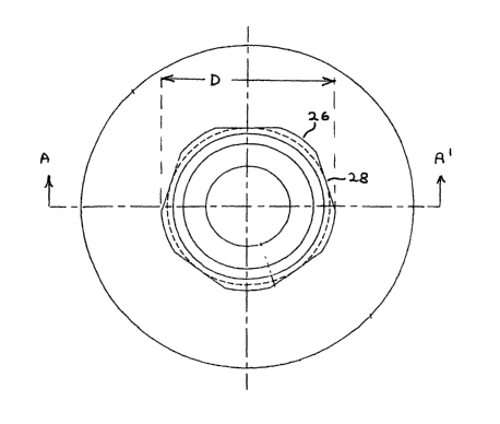
Figures 1 and 2 show a male stud 10 according to the invention comprising a
flange
portion 12 and a generally cylindrical engaging portion 14. The flange portion
12 is
generally disc shaped and has a central slightly tapered bore 16 the remaining
annular part 18 of the flange having a plurality of circumferential grooves 20
on the
underside 22. The bore 16 is tapered at an angle oc to the axis of the bore
16, where
a is typically 5°. The topside 22 of the flange is integrally formed
with the
cylindrically engaging portion, which extends axially therefrom. The
cylindrically
engaging portion 14 comprises a plurality of circumferentially extending
arcuate
CA 02491121 2004-12-29
WO 2004/002257 PCT/GB2003/002748
3
portions 26, each such portion being separated from the next by a flat faced
portion
28. Figure 1 shows five such arcuate and flat faced portions. The internal
wall of the
cylindrically engaging portion 14 comprises an un-tapered section 30 extending
from the flange 12 and a tapered section 32 extending therefrom. This section
32 is
tapered outwardly at an angle (3 to the axis of the cylindrically engaging
portion 14,
where (3 is typically 18°. The central part of the external wall 34 of
the cylindrically
engaging portion also tapers outwardly at an angle (3 to the axis of bore 16;
there
being a curved, and preferably arcuate wall portion 36 between the inner and
outer
tapered walls of the cylindrically engaging portion 14.
A male stud according to the invention may be used with known female sockets.
Figures 4 and 5 show such a socket 40 comprising a flange portion 42 similar
in
configuration to the flange portion 12 of the male stud described above.
Flange
portion 42 has a generally cylindrically extending female socket portion 44
dimensioned to snugly engage the circumferentially extending arcuate portions
26 of
male stud 10.
Figure 3 shows the male stud 10 as it is being engaged within female socket
40.
Known male stud members having a continuous curved outer wall 34 may also
engage such a socket. However, the flat portions 28 of the male stud according
to
the invention allow the force required to subsequently separate the male and
female
members to be controlled. This is achieved by varying the circumferential
length of
the flat portions 28 relative to the circumferentially extending arcuate
portions 26
and also by varying the angle (3. By this means this separation force can be
chosen to
be suitable for a particular fabric. This is especially advantageous when the
fastener
is being used with so called "stretch fabrics" such as LYCRA TM.
In use, the male stud and female socket each need to be fixed to fabric by
attachment means. Figures 6 and 7 show a suitable attachment means comprising
a
post 50 and head 52. Head 52 has a smooth top face 54 and an underface 56 with
a
CA 02491121 2004-12-29
WO 2004/002257 PCT/GB2003/002748
4
plurality of larger spikes 58 and smaller spikes 60 protruding therefrom. Post
50
extends axially away from the underface 56 and has a tapered of spiked end 62.
Thus, in use spike 62 of post 50 pierces the fabric to which it is attached
such that
this fabric is subsequently held sandwiched between the attachment means and
the
male stud or female socket by the engaging action of post 50 within the
tapered bore
16 of male stud 10 or a similar bore in female socket 40.
While the male stud described above has 5 flat faces the number may vary; for
example 7 faces may be used. Preferably, there will be an odd number of flat
faces.
This will result in a flat face diametrically opposite an arcuate portion;
such an
arrangement advantageously assists a "peeling action" during disconnection of
the
male and female members. However, while an odd number of flat and arcuate
portions is preferred the invention may be used with an even number of flats
and
arcuate portions. While the arcuate portions are preferably true arcs of a
circle, other
curved shapes: for example parabolic portions are possible. Likewise while the
flats
are preferably simple flat surfaces other configurations are possible; for
example a
generally "U-shaped" recess between the arcuate portions. The important
characteristic is that the flats have a shape that ensures that they do not
significantly
abut female socket portion 44 during connection. As explained above, this
allows a
reduced separation force, that can be selected by the designer to suit a
particular
fabric, compared with a conventional male stud.
The diameter D (see Figure 2) of the engaging portion 34 of the male stud 10
may
be 3 to 7 mm, and is preferably about 5 mm. The maximum diameter d (see Figure
1) of tapered bore 16 of the male stud 10 may be 2 to 3 mm, and is preferably
about
2.5 mm.
Snap fasteners according to the invention can be made from a variety of
materials
including plastics, Acetal TM resin such asDELRIN RoM is particularly
suitable.
CA 02491121 2004-12-29
WO 2004/002257 PCT/GB2003/002748
While angle ~i of the male stud is preferably about 18° values within
the range 16°
to 20° and indeed 13° to 23° are possible.