Note: Descriptions are shown in the official language in which they were submitted.
CA 02491198 1997-08-11
Ion Storage Time-~~ FIiQ6t Mass Spectrometer
Field of the Invention
This invention relates in general to mass spectrometers and in particular to
the use of time-of flight (TOFU mass spectrometers in combination with two
dimensional ion traps that are also used as ion guides and ion transport
lenses.
Background of the Invention
In a time-of flight mass spectrometer, ions are accelerated by electric fields
out of an extraction region into a field free flight tube which is terminated
by an
ion detector. By applying a pulsed electric field or by momentary ionization
in
constant electric fields, a group of ions or packet starts to move at the same
instant in time, which is the start time for the measurement of the flight
time
distribution of the ions. The flight time through the apparatus is related to
the
mass to charge ratios of the ions. Therefore, the measurement of the flight
CA 02491198 1997-08-11
2
time is equivalent to a determination of the ion's m/z value. (See, e.g., the
Wiley and McLaren; and, the Laiko and Dodonov references cited below).
Only those ions present in the extraction zone of the ion accelerator, (also
referred to as "the pulser"), in the instant when the starting pulse is
applied
are sent towards the detector and can be used for analysis. In fact, speaal
care
must be taken not to allow any ions to enter the drift section at any other
time, as those ions would degrade the measurement of the initial ion package.
For this reason, the coupling of a continuously operating ion source to a
time-of flight mass spectrometer suffers from the inefficient use of the ions
created in the ion source for the actual analysis in the mass spectrometer.
High repetition rates of the flight time measurements and the extraction of
ions from a large volume can improve the situation, but the effective duty
cycles achieved varies as a function of mass and can be less then 10% at low
mass.
If extremely high sensitivity of the mass analysis is required or if the
number of ions created in the ion source is relatively small, there is need to
make use of all the ions available. This requires some sort of ion storage in-
between the analysis cycles. Time-of flight instruments that use de plate
electrode configurations or quadrupole ion traps for ion storage have been
built and operated successfully. (See e.g., the Grix, Boyle, Mordehai, and
Chien references cited below). While the storage efficiency of do
configurations is limited, with quadrupole ion traps a compromise between
efficient collisional trapping and collision free ion extraction has to be
found.
In the present invention, a multiple pumping stage linear two dimensional
multipole ion guide is configured in combination with a time-of-flight mass
CA 02491198 1997-08-11
,:
r ~ _
3
spectarometer with any type of ionization source to increase duty cycle and
thus
sensitivity and provide the capability to do mass selection. Previous systems,
such as the ion trap/time-of flight system of Lubman (cited below), have
combined a storage system with time-of-flight, however, these systems'
trapping time are long, on the order of a second, thus not taking full
advantage of the speed at which spectra can be acquired and -thereby limiting
the intensity of the incoming ion beam. In addition, the ion trap is strictly
used as the acceleration region and storage region. Also, 100% duty cycle is
not possible with the ion trap TOF system due to the fact that the ion trap
can
not be filled and empty at the same time; in addition, there are currently
electronic limitations (See e.g., Mordehai, cited below), whereas in this
embodiment it is one of the possible modes of operation.
The use of a two dimensional multipole ion guide to store ions prior to
mass analysis has been implemented by Dolnikowski et al. on a triple
quadrupole mass spectrometer. This combination, in fact, has become routine
analysis technique for triple quadrupoles. A more recent combination was
made by Douglas (U.S. Patent No. 5,179,278) who combined a two
dimensional multipole ion guide with a quadrupole ion trap mass
spectrometer. Both of these systems are quite different from the current
embodiment. In both of the above systems, the residence times of the ions in
the linear two dimensional quadrupole ion guide were over 1-3 seconds,
whereas, in the current embodiment the ions can be stored and pulsed out of
the linear two dimensional multipole ion guide at a rate of more than
10,000/sec, thus utilizing much faster repetition rates. Due to the inherent
fast
mass spectral analysis feature, of the time-of-flight mass analyzers,
continuously
generated incoming ions are analyzed at a much better overall transmission
efficiency than the dispersive spectrometers such as quadrupoles, ion traps,
sectors or Fourie~r Transform mass analyzers. When an ion storage device is
CA 02491198 1997-08-11
~.
4
coupled in front of a dispersive mass analyzer instrument, the overall
transmission efficiency of an instrument, no doubt, increases; however, since
the ion fill rate into the storage device is much faster than the full
spectral
mass analysis rate, the overall transmission efficiencies are limited by the
mass spectral scan rates of the dispersive instruments which are at best on
the
order of seconds. Time-of flight mass analyzers, on the other hand, can take
full use of the fast fill rates of the incoming continuous stream of ions
since
the mass spectral scan rates of 10,000 per second and more can well exceed
these fill rates into a storage device.
Also unique to this embodiment is the fact that the ion packet pulse out of
the linear two dimensional multipole ion guide forms a low resolution time of
flight separation of the different m/z ions into the pulser where the timing
is
critical between when the pulse of ions are released from the linear two
dimensional multipole ion guide and the time at which the pulser is activated.
This is to say that the linear two dimensional multipole ion guide pulse time
and the delay time to raise the pulser can be controlled to achieve 100% duty
cycle on any ion in the mass range or likewise a 0% duty cycle on any ion in
the mass range or any duty cycle in between. Also, as pointed out by Douglas
(U.S. Patent No. 5,179,278), an ion guide can hold many more ions than what
the ion trap mass analyzer can use. This decreases the duty cycle of the
system if all trapped ions are to be mass analyzed. In contrast, that is not
an
issue in the current embodiment.
As the linear two dimensional multipole ion guide trap is filled with more
ions, the space charging effects or coulombie interactions between the ions
increase resulting in two major consequences. First, the mass spectral
characteristics may change due to overfilling of the storage device where more
fragmentation will occur due to strong ionic interactions. Second, the
internal
CA 02491198 1997-08-11
5
energy of the ions will increase, making it. harder to control and stop the
ions
going into a mass analyzer device. The above problems can again be
overcome using a time-of-flight mass analyzer at fast scan rates which will
not
allow excessive charge build up in the storage ion guide. Operating at very
fast acquisition rates, time-of flight instrument does require intricate
timing of
the trapping and the pulsing components.
Brief Description of the Invention
It is the principal object of this invention to provide means for increasing
the deteedon limits of a continuous stream of ionic chemical species
generated externally in a time-of flight mass spectrometer.
It is a further object of this invention to provide means for increasing the .
detection limits of said time-of flight instrument by increasing the duty
cycle of
the mass analysis.
In accordance with the above objects, a two dimensional ion guide device
with accompanying ion optics and power supplies, switching circuitry, and
tinung device for said switching circuitry is provided to increase the ion
throughput into the time-of flight mass analyzer.
These and further objects, features, and advantages of the present invention
will become apparent from the following description; along with the
accompanying figures and drawings.
Brief Description of the Drawings
CA 02491198 1997-08-11
6
FIG. 1 is a schematic representation of a simple linear time-of flight mass
analyzer utilizing orthogonal acceleration with an atmospheric pressure
ionization source.
FIG. 2 is a schematic representation of a simple reflectron time-of flight
mass analyzer utilizing orthogonal acceleration with an atmospheric pressure
ionization source.
FIG. 3 is a schematic drawing of the interface ion optics between the ion
source and the mass analyzer.
FIG. 4 is a schematic drawing of the interface ion optics between the ion
source and the mass analyzer using a two dimensional ion trap.
FIG. 5 is the detailed view of the ion guide and the surrounded ion optics
(A), cross section of the -multipole ion guide with six rods (B),
electrostatic
voltage levels on the said ion optics when the ions are released (C) and
trapped (D).
FIG. 6 is the relative timing diagram of the ion guide eidt lens and the time-
of flight repeller lens voltages.
FIGS. 7A and 7B are the time-of flight mass spectral comparison between
the continuous and ion storage mode of operations.
FIG. 8 is a schematic representation of a simple linear time-of flight mass
analyzer utilizing axial acceleration with an atmospheric pressure ionization
source.
Detailed Description of the Preferred Embodiments
Among the many atmospheric pressure ionization time-of flight mass
spectrometer configurations covered by prior art, FIG. 1 and FIG. 2 show the
two basic time-of flight instruments used in this study demonstrating the
CA 02491198 1997-08-11
7
present invention. FIG. 8 also shows an alternative but less frequent
configuration used in our studies. The instruments contain an external
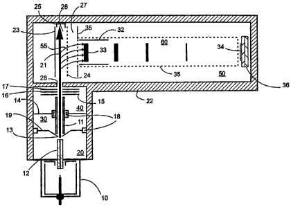
atmospheric pressure ion source 10 and a means for transporting the ions
from the atmospheric pressure ionization source to the mass analyzer all of
which are encased by the vacuum housing walls 22. Both the ions and the
background gas are introduced into the first stage pumping region 20 by
means of a capillary interface 12 and are skimmed by a conical electrostatic
lens 19 with a circular aperture 13. The ions are formed into a beam 21 by a
multipole ion guide having round rods 11 and are collimated and transferred
into the pulsing region 26 of the time-of flight mass analyzer by transfer ion
optic lenses 15, 16, and 17. The mutipole ion guide can be a multipole ion
guide extending through multiple vacuum pumping stages according to the
preferred embodiment. Multipole ion guides extending through multiple
vacuum pumping stages are described in U.S. Patent No. 5,652,427 dated July
29,
1997.
Alternatively, separate multipole ion guides in separate vacuum pumping
stages can be used.
Electrically insulating materials such as spacers 18 are used to isolate the
various ion optic lenses throughout the apparatus. Along the path of the
transfer ion optics, the gas density is reduced going through four different
pumping stages. The skimmer orifice separates the gas flow between the first
and the second pumping stages 20 and 30, the ion guide support bracket 14
and the ion guide itself acts as a separator between the pumping stages 30 and
40. A hole 28 in the vacuum housing 22 separates the third pumping stage 40
from the fourth pumping stage 50 where the time-of flight mass analyzer
CA 02491198 1997-08-11
8
components reside. The four vacuum stages are pumped conventionally with a
combination of turbo and mechanical pumps.
The time-of flight mass analyzer shown in FIG. 1 and FIG. 2 are said to be
operating in an orthogonal injection mode because ions generated outside of
the spectrometers are injected perpendicularly to the direction of the
accelerating fields 26 and 27 defined by the electrostatic lenses 23, 24, and
35
(See e.g., the O'Halloran et al., Dodonov et al., USSR Patent SU 1681340
references cited below). The ion beam 21 enters the time-of flight analyzer
through an aperture 28 and traverses the first accelerating or the extraction
region 26. A Faraday cup 25 is used to monitor and optimize the ion current
of the ion beam 21 into the region 26 when the electric field is off, i.e. the
voltage on the repeller plate 23 is equal to the voltage on the draw-out plate
24. Typically that would be the ground voltage potential. By applying a
pulsed electric field momentarily between the repeller lens 23 and the draw=
out lens 24, a group of ions 33 starts to move instantaneously in the
direction
~55, through the second stage acceleration field set by the plates 24 and 35
and
towards the field free drift region 60 surrounded by the flight tube 35. The
pulsed electric field generated by the pulsing of the repeller lens 23
establishes
the start time for the measurement of the flight time distribution of the ions
arriving at the detector 36. The flight time through the apparatus is related
to
the mass to charge ratios of the ion. Therefore the measurement of the flight
time is equivalent to a determination of the ion's m/z value. To offset or
adjust the direction of the ion packet 33 to hit the detector 36, set of
deflectors 32 may be used after the acceleration region 27 and inside the
field
free drift region 60. If the deflectors are not used with orthogonal
injection,
the detector has to be placed off axis at a position to account for the energy
of
the ions in the direction of the ion beam 21.
CA 02491198 1997-08-11
9
The mass resolution of a time-of flight mass spectrometer is defined as
m/Am = tl2dt where m is the ion mass, Om is the width of the ion package
arriving at the detector at full width half maximum (FWHM), t is the total
flight time of this ion, and ~t is the arrival time distribution at the
detector
measured at FWHM. As a result, higher resolution can be achieved in one of
two ways: increase the flight time of ions or decrease the arrival time
distribution of the ions at the detector. Given a fixed field free drift
length,
the latter is achieved in the present mass spectrometer with a two stage
accelerator of the type first used by Wiley and MeLaren. The electric fields
in
the two acceleration regions 26 and 27 are adjusted by the voltages applied to
the lenses 23; 24, and 35 such that all ions of the same m/z start out as a
package of ions 33 with a finite volume defined by the acceleration region 26
and end in a much narrower package 34 when they hit the detector. This is
also called the time-space focusing of the ions which compensates for the
different initial potential energy of the ions located in different positions
in
the electric field in region 26 during the pulse. The dme-space foccising of
the
ions does not however compensate for the different energy distribution of the
ions along the direction of the acceleration field before the field is turned
on.
The degree of the energy spread component of the ions in the acceleration
axis determines the time distribution of the ions arriving at the detector.
The
larger the spread of energy of the ions in this direction, the lower will be
the
mass resolving power of the instrument. The orthogonal injection of the ions
does minimize, to some degree, the energy spread of the externally injected
ions in the direction of acceleration resulting in a narrower package of ions
hitting the detector. To further increase the resolution of the time of flight
instrument caused by the energy spread of the ions, a reflectron of the type
first used by Mamyrin (cited below) can be used. FIG. 2 shows such an
instrument which is the same as in FIG. 1, except a reflectron 41 is added for
operating the mass analyzer in a higher resolution and mass accuracy mode.
CA 02491198 1997-08-11
l~
The coupling of continuously operating ion sources 10 to a time-of flight
mass spectrometer suffers from the inefficient use of the ions created in the
ion source for the actual analysis in the mass spectrometer. High repetition
rates of the flight time measurements counted by the pulsing of the repeller
lens 23 and the extraction of ions from an elongated volume 26 can improve
the situation, but effective duty cycles achieved are still of the order of 1
to
50%.
To demonstrate the point, consider a continuous beam of ions 21 in FIG: 3
having a mixture of three ions 52, S3, and 54 with molecular weights 997
(Ml), 508 (Mz), and 118 (M3) entering the pulsing region 26 with electrostatic
energy of 10 eV. With these parameters, the approximate velocity of the ions
going through the acceleration region 26 at the absence of the field would be
4 mm/E,cs, 1.9 mm/~.s, and 1.4 mm/~s, respectively. If practical experimental
parameters, for example, 10,000 repetition rate per second of the repeller
lens
26 (a single scan lasting 100~s) and 20 mm of pulsing region length
determined by the mesh size opening 38 on the lens 35, are used, for every
one ion of mass M, 52, M2 53 and M3 54, going in the direction 55 of the
time-of flight analyzer detector, seven, ten, and twenty ions will be lost
going
in the direction 21. The approximate calculated duty cycles for the ions M,
52, M2 53, and M3 54, will result in 14%, 10%, and S%, respectively.
In order to achieve higher extraction duty cycles with continuous ion beams
several parameters can be adjusted. For example, repetition rates of 20,000
Hz or more can be used, the energy of the ions can be lowered, or the
extraction region can be extended in the direction of the ion beam 21.
However, many of these changes will result in an increase of duty cycles by at
best a factor of two before practical limitations can be exceeded. Difficult
to
build or expensive to buy mass analyzer components such as detectors with
CA 02491198 1997-08-11
Z1
larger surface area, faster data acquisition systems etc., will be needed to
achieve higher duty cycles.
To make use of the limited number of ions generated in the ion source 10,
some sort of ion storage mechanism in-between the analysis cycles is required.
FIG. 3 shows a section of a time-of flight mass spectrometer that utilizes an
existing RF-only multipole ion guide being used in the continuous ion mode of
operation. FIG. 4, FIG. S, and FIG. 6 show the same multipole ion guide
being used in the ion storage mode of operation with appropriate power
supply and pulse d 'rne and delay generators.
In recent years, the commercial use of such RF-only multipole ion guides
have been practiced widely in continuous mode, especially in mass
spectrometers interfaced with atmospheric pressure ionization (APn sources.
The number of rods used in the multipole ion guide assemblies may vary; the
examples in this imrention will show predominantly hexapole, meaning six
round, equally spaced in a circle, and parallel, set of rods 11 as shown in
FIG.
SB. The alternate rods 11 are connected together to an oscillating electrical
potential. Such a device is known to confine the trajectories of charged
particles in the plane perpendicular to the ion beam axis 2I, whereas motion
in the axial beam direction is free giving rise to the term, "two dimensional
ion
trap". Depending on the frequency and amplitude of the oscillating electrical
potential, stable confinement can be achieved for a broad range of values of
the mass to charge ratio along the beam axis 2I. A static bias voltage
potential 76 is applied to all the rods to define the mean electrical
potential of
the multipole with respect to the ion guide entry conical electrode 19 with
voltage 75 and with respect to the ion guide exit electrode 15 with voltage
value 77 or 78.
CA 02491198 1997-08-11
12
As seen in FIG. SC, in the continuous mode of operation, for a positively
charged stream of ions Z1 to enter and be focused into the ion guide through
a skimmer orifice 13, the voltage value 75 applied to the conical electrode 19
has to be higher than the bias voltage value 76 applied to the ion guide rods
11. By the same token, to push and focus the ions beyond the ion guide, a
voltage value 77 even less than the bias voltage value 76 needs to be applied
to the ion guide exit lens electrode 15. When the ion guide is operated in the
storage mode as $een in FIG SD, the voltage value on the exit lens electrode
15 is raised from 77 to 78 which is higher than the ion guide bias voltage 76.
This higher voltage value 78 on the lens electrode 15 repels the ions in the
exit
region 72 of the ion guide back towards the entrance region 71 of the ion
guide. As evident from FIG. SD, the voltage values set in this manner form a
potential well in the longitudinal direction of the ion guide efficiently
preventing the ions from leaving the ion guide.
A particularly useful feature of the ion guide in regards to this invention is
the higher gas pressure in the ion entry region 71 and the region up to the .
second and third pumping stage partitioning wall 14 inside the ion guide.
Due to the expanding background gas jet, this region 30 is under viscous flow
pressure regime with gas flowing and becoming less dense in the direction of
the ion beam 21. This feature accomplishes two important functions in the
time-of flight instrument. One, due to collisional cooling, it sets a well
defined
and narrow ion energy of the beam 21. Two, it allows high efficiency trapping
of the ions along the ion guide enclosed by the rods 11, the conical lens 19
and the exit lens 15.
Both in the continuous mode of operation and in the storage mode, the
final electrostatic energy of the ions entering the time-of flight analyzer
pulsing
region 26 is determined by the voltage difference set between the ion guide
CA 02491198 1997-08-11
13
bias voltage 76 and the time-of flight repeller plate 23 when the field is
off.
Due to collisions with the molecules of the dense gas jet in the region 71,
the
ions do not gain kinetic energy in the electric field but slide gradually down
the electric potential well shown in FIG. SD. In this way, they attain a total
energy close to the bias potential 76.
The ion guide rods 11 extend both through the second 30 and third 40
pumping stages without any interruptions; they allow ions to flow freely in
the
forward and backward directions in the ion guide with close to 1003'0
efficiency. As ions move backwards towards the conical lens 19, the higher gas
density moving in the forward direction prevents the ions from hitting the
walls of the conical lens. The ions are efficiently brought to thermal
equilibrium by these multiple collisions with residual or bath gas molecules
while ions front the ion source are constantly filled into the trap through
the
aperture 13. The higher pressure in the vacuum stage 30 also allows ions to
go back and forth multiple times inside the ion guide. As a result, the ion
guide exit lens voltage 78 can be adjusted freely not only higher than the
bias
voltage 76, but also higher than the conical lens voltage 75. If the higher
pressure region 71 was absent in the ion guide, a voltage setting 78 higher
than 75 would have crashed the ions into the conical lens 19 after a single
pass. Without the higher pressure region 71, the voltage settings 75, 76 and
78
would be more critical and difficult to set with respect to each other for
efficient trapping of the ions in the ion guide.
As the voltage on the exit lens 15 is switched from level 78 to 77 for a short
duration (of the, order of microseconds), high density ion bunches are
extracted collision free from the low pressure storage region 72 and injected
into the orthogonal time-of flight analyzer. The mechanism for the storage
mode of operation can be seen in FIG. 4. The ions are subsequently
CA 02491198 1997-08-11
14
accelerated by means of additional electrodes 16 and 17. These electrodes in
the present system are held at constant potentials, but they can be switched
synchronously to the switching of the lens 15. After being pulsed out of the
region 72, all ions of the packet originally extracted will have in first
order
approximation the same final kinetic energy qUo, where Uo is the total
accelerating potential difference between the ion guide bias voltage 76 and
the
time-of flight repeller lens voltage when the field is off in the pulsing
region
26. Then, ions of a specific mass to charge ratio will have a final velocity
which is proportional to the reciprocal square root of this ratio:
2xgx
va=kIx
m
(1)
Here, k, is a constant, q=ze is the charge of the ion, and m is its mass. Ions
will travel a distance L to arrive at the same point in the pulsing region 26
after a certain time T shown by
0
k2 is a constant that takes into account the ion acceleration process. Hence,
ions with a different m/z ratio will pass a point in region 26.
i z kl
CA 02491198 1997-08-11
ZS
Accordingly, the initial ion package is spread out in space along the region
26
in the direction of the ion beam.
FiG. 6 shows the driving mechanism and the timing sequence between the
ion guide exit lens 15 and the time-of flight repeller lens 23 for a single
cycle,
i.e. a single mass spectral scan. The trace 83 shows the ion guide exit lens
voltage status switching between the two voltage levels 77 and 78 and the
trace
82 shows the repeller lens voltage status switching between the two levels 79
and 80. The power supply 91 sets the desired upper and lower voltage levels
to be delivered to the lenses at all times. The electrically isolated fast
switching circuitry 92 synchronously controls the desired voltage levels of
the
len electrode iS and the repeller plate 23 to be switched back and forth
during
the designated time intenials controlled by the pulse and delay generating
device 93, which is an accurate timing device, which in turn is controlled by
the user interface.
As an example to the ion storage mode of operation, let us again use the
same mixture of ions Ml, M2, and M3 of ionic masses 997, 508 and 118 as used
above in continuous mode of operation. As shown in FIG. a, and FIG. 6 the
pulsed ion beam of duration tl from the region 72 is injected between the
parallel plates 23 and 24 when the plates are initially held at the absence of
an
electric field, i.e. voltage level 79 on the repeller lens 23. According to
the
above equation (3), Lighter ions moving faster than the heavier ions, the
three
masses will start to separate from each other in the region 26. After a
certain
variable delay t2, the electric field in the region 26 is pulsed on for a
short
period of time t3 by the repeUer plate 23. The delay time t2 can be changed
to allow different sections of the original ion beam i.e. different m/z
packages,
to acxelerate perpendicular to their original direction towards the flight
tube
35 to be detected for mass analysis. In this example, a delay time t2 was
CA 02491198 1997-08-11
16
chosen to pulse only a narrow range of ions centered around mass (M=) 53
which were accelerated in the direction 63 at the instant the field was turned
on. At the same instant , both the masses M, 52 and M3 54 will hit the sides
of the lenses moving in the approximate direction 62 and 64 and will not be
detected by the mass analyzer.
The range of the detectable m/z window around a certain mass can be
adjusted with several parameters. For a fixed exit lens pulse width tl and a
delay time t2, the width of the mesh aperture 38 and the detector 36, for
example, determines the m/z packet size along the direction 21 that is allowed
to pass. The wider the aperture size on the mesh 38 and the detector 36, the
larger will be the detected mass range. In addition, the pulse width tl of the
lens 15 can be kept longer to sample a wider mass range of ions coming from
the part of the ion guide that is further inside and away from the exit lens
15.
As the pulse width tl of the lens 15 is kept longer, multiple time-of flight
ejection pulses are possible for one ion trap extraction cycle approaching the
continuous mode of operation.
FIGS. 7A and 7B show the actual experimental results acquired using both
the continuous and ion storage mode of operations for a sample using a
mixture of ions used in the above examples. The actual sample was a mixture
of three compounds Valise, tri-tyrosine, and hexa-tyrosine. Upon electrospray
ionization of this mixture, the predominant molecular ions with nominal
masses 118, 508, and 99'7 are generated in the ionization source 10. The
bottom trace of FIG. 7A shows all three of these ions detected and registered
as peaks 73, 71, and 74 when the mass spectrometer was in the continuous
mode of operation. The top trace mass spectrum in FIG. 7A shows the
results when the mass spectrometer was changed to the ion storage mode of
operation. Both modes were acquired in similar experimental conditions. The
CA 02491198 1997-08-11
17
acquisition rate i.e. the repetition rate counted by the repeller lens was
8200
per second. Each trace represents 4100 full averaged scans. As seen from the
top spectral trace, there is only one predominant registered peak 72 in the
spectrum. This peak corresponds to a molecular ion 508 enhanced in signal
strength by about a factor of ten with respect to the peak 71 in continuous
mode of operation. For the reasons explained in above examples, both of the
molecular ions 118 and 997 are absent from the ion storage mode spectral
trace as expected. The signal intensity increase comes from the fact that all
of
the ions that would otherwise be lost in the continuous ion mode were actually
being stored in the ion guide for the next scan. According to the above
example, fox the continuous mode of operation, the approximate duty cycle
calculated for the 508 peak at 8,200 scans/s would be 9% i.e. one out of every
twelve ions being detected. As the experimental results suggest in the ion
storage mode of operation at 8,200 scans/s in FIG. 7A, most of the lost ions
predicted in the continuous ion mode were recovered. FIG. 7B shows the
same spectral traces, except the m/z region is expanded between 500 and 520
to show the isotopic peaks in more detail. The slight shift between the peaks
71 and 72 are due to the different tuning conditions of the ions by the lenses
16 and 17 that lands the ions in different position in the acceleration region
26. These differences resulted in the slight arrival time shifts of the ions
on
the detector resulting in different mass assignments.
Consequently, in summary and in conclusion, an improved apparatus
for analyzing ionic species using a time-of flight mass analyzer is provided
herein. In the preferred embodiment, the apparatus, has an atmospheric
pressure ionization source which produces ions for transmission to a time-of-
flight mass analyzer. The apparatus. has a two dimensional ion guide
enhancing the efficiency of transmission of the ions, operating between the
atomospheric pressure ion source and the time-of-flight mass analyzer, the ion
guide having a set of equally spaced, parallel, multipole rods and operating
in
CA 02491198 1997-08-11
1g
the RF-only mode of operation, having an ion aWance section where the ions
enter said ion guide and ion exit section where the ions exit the ion guide,
and
having an ion entrance lens placed at the ion entrance section and an ion
eatit
lens at the ion exit section. The ion guide is positioned such that the ion
entrance section of the ion guide is placed in a region where background gas
presstue is at viscous flow, and such that the presstus along the ion guide at
the ion exit section drops to molecular flow pressure regimes without a break
in the structure of the ion guide. The ion guide is operated in the ion
storage
mode using a fast vohage switching device to switch voltage levels of the ion
guide exit lens. The apparatus further has a time of light acceleration region
the ions are pulsed out momentarily to be mass analyzed, witty the ions being
injected into the time-of flight acceleration region in a direction orthogonal
to
the diraxion of the acceleration field of the time-of flight acceleration
region.
A detector is also provided where the ions are mass analyzed according to
their arrival times, and an accurate timing device is provided that
synchronizes
the voltage swit,;h device, and which determines the respective voltage
levels and the duration of the voltage levels of the ion guide exit lens and
the
time-of flight acceleration field to each other.
Ahhough the invention has been described in terms of specaflc preferred
embodiments, it will be obvious and understood to one of ordinary skill in the
art
that various modif rations and substitutions are contemplated by the invention
disclosed herein and that all such modifications and substitutions are
included
within the scope of the invention as defined in the appended claims.
References Cit~,~d:
The following references have been referred to above:
CA 02491198 1997-08-11
19
U.S. Patelrt Documents:
5,179,278 Jan. IZ,I993 D. J. Douglas
2,685,035 July 27, 1954 W. C. Wiley
foreign Patent Documents:
SU 1681340 A1 Feb. 25, 1987 USSR Patent Dodonov
et al.
Other References Cued:
C. Beaugrand and G. Devant, Ion Kinetic Energy Measurement on Tandem
Quadrupole Mass Spectrometers, 35 th ASMS Conference on Mass
Spectrometry and Allied Topics, Denver, CO (1987).
J.G. Boyle, C.M. Whitehouse, J.B. Fenn, Rapid Commun: Mass Spectrom. 5,
400
(1991).
B.M. Chien, S.M Michael, D. Lubman, Int. J. Mass Spect. Ion Proc. 131, 149
(1994).
J. H. J. Dawson, M. Guilhaus, Rapid Commun. Mass Spectrom. 3, 155 (1989).
A. F. Dodonov, I. V. Chernushevich, V. V. Laiko, 12'" Int. Mass Spectr.
Conference, Amsterdam (1991).
CA 02491198 1997-08-11
G.G Dolnikowski, M.J. Kristo, C.G. Enke, and J.T. Dawson, Intl. Jour. of
Mass Spec. Ion Proc., 82, p.l-1S, (1988), Ion Trapping Technique for
Ion/Molecule Reaction Studies in the Center Quadrupole of a Triple
Quadrupole Mass Spectrometer.
R. Grix, U. Gruner, G.Li, H. Stroh, H. Wollnik, Int J. Mass Spect. Ion Proc.
93,323(1989).
R. F. Herzog, Z. Phys. 89 (1934), 97 (1935); Z. Naturforsch 8a, 191 (1953), .
10a, 887
{1955).
V. I. Karataev, B. A. Mamyrin, D. V. Shmikk, Sov. Phys. Tech. Phys. 16, 1177
( 1972).
V.V. Laiko and A.F. Dodonov, Rapid Commun. Mass Spectrom. 8, 720
( 1994).
B. A. Mamyrin, V. I. Karataev, D. V. Shmikk, V. A. Zagulin, Sov. Phys. JETP
37, 45
(1973).
S.M Michael, M. Chien, D.M. Lubman, Rev. Sci.Instrum. 63 (10), 4277
( 1992).
O. A. Migorodskaya, A. A. Shevchenko, T. V. Chernushevich, A. F. Dodonov,
A. I.
Miroshnikov, Anal. Chem. 66, 99 (1994).
CA 02491198 1997-08-11
21
A.V. Mordehaj, G. Hopfgartner, T.G. Huggins, J.D. Henion, Rapid Common.
Mass
Spectrom. 6, 508(1992).
A. Mordehai, J. Karnicky, B. Limbek, and S. E. Buttrill, Jr., "A New LC
Electrospray Ion
Trap Time-Of Flight Mass Spectrometer", 43 rd ASMS Conference on
Mass
Spectrometry and Allied Topics, Atlanta, GA (1995).
G.J. O'Halloran, R.A. Fluegge, J.F. Betts, W.L.Everett, Report No. ASD-TDR
62-644, Prepared under Contract AF 33(616)-8374 by The Bendix
Corporation Research Laboratories Division, Southfield, Michigan
(1964).
A. N. Verentchikov, W. Ens, K. G. Standing, Anal. Chem. 66, 126 (1994).
W.C. Wiley, LH. McLaren, Rev. Sci. Inst. 2b, 1150 (1955).