Note: Descriptions are shown in the official language in which they were submitted.
CA 02491220 2004-12-23
2
Fluid separatinp device
Field of the Invention
The invention relates to a fluid separating device for separating gases and
liquids in
several fluid flows and for separating liquid-soluble components from the
gases. The
device comprises a lower section with a fluid feeding device and a liquid
discharging
device, an upper section with a fluid feeding device and a gas discharging
device, a
contact device which is constructed in such a manner that gas which rises from
the
lower section to the upper section comes into contact with liquid which sinks
from the
upper section into the lower section, and a measuring device for determining
the
quantity of liquid and/or alterations of the quantity of liquid in the lower
section.
The fluid separating device according to the invention is particularly suited
for
controlling the fluid flows in fuel cell systems, in particular in DMFC
systems.
Prior Art
In some fuel cells, instead of a pure fuel component, diluted fuel is used
which will be
designated below as fuel mixture, even if not all components of this mixture
are
oxidisable substances.
In a direct methanol fuel cell (DMFC), the fuel mixture on the anode side
consists, for
example, of methanol dissolved in water, the first being the actual fuel. The
water of
this fuel mixture does not appear in the net accounting equation of the cell
reaction,
as distinguished from the water arising as reaction product (on the cathode
side),
which has to be discharged from the cell as the reaction product carbon
dioxide
arising on the anode side. That is, the anode fluid undergoes a depletion of
methanol
and an enrichment of CO2 on its path from the anode inlet to the anode outlet.
In
order to be able to optimally utilize the depleted anode fluid, too, and to
avoid liquid
losses, as a rule, a circuit flow is provided on the anode side, wherein the
anode fluid
is again enriched with fuel (corresponding to its consumption) after it has
left the
CA 02491220 2004-12-23
3
anode outlet and fed to the anode inlet again. In the process, however, carbon
dioxide has to be discharged from the circuit flow.
In the DMFC system, the major proportion of carbon dioxide is present in a
gaseous
form as the solubility limit of carbon dioxide in the fuel mixture is quickly
exceeded.
(As water is quantitatively the dominant substance in the fuel mixture, the
solubility
limit of carbon dioxide in the fuel mixture approximately corresponds to that
of carbon
dioxide in water.) That is, the fluid exiting at the anode outlet is as a rule
no
homogenous phase but a gas/liquid mixture. Due to the flow conditions,
however, the
liquid and the gaseous phases are not physically strictly separated from one
another;
gas bubbles are rather formed in the liquid.
In the DMFC system, the liquid phase exiting at the anode outlet is a
water/methanol
solution, as a rule saturated with C02; in the gaseous phase, CO2 enriched
with
water vapour and methanol vapour is dominant. Thus, in an unregulated waste
gas
removal, the fuel (here: methanol) present in the gaseous phase would be thus
lost
for the system, which is unacceptable not only for economical, but also for
health and
safety reasons. Furthermore, water in the form of water vapour would be lost,
so that
for maintaining the operation conditions, an external water supply would be
necessary, which is unacceptable with respect to the practical use of the fuel
cell.
The above-mentioned problems have to be taken into consideration in the
conception
and operation of a DMFC system, which is conventionally done as described
below.
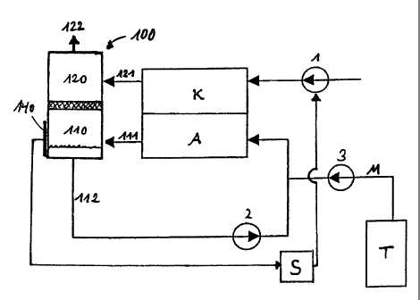
Fig. 1 is a view of a typical fuel cell system according to the present
intemal prior art.
The DMFC fuel cell is schematically and only for simplification divided into a
cathode
side K and an anode side A. ("Side" is not to be understood figuratively: in
fact, a
DMFC fuel cell consists, as a rule, of a so-called stack with alternating
anode and
cathode areas).
The fluid on the cathode side comprises an oxidising substance, such as
oxygen,
which is supplied by means of a metering device 1 in the form of normal
ambient air.
CA 02491220 2004-12-23
4
In the process, the non-usable substances of the air, such as nitrogen, but
also water
arising as reaction product and CO2 diffusing from the anode to the cathode
side, are
discharged as fluid 21 at the outlet.
The fluid on the anode side further comprises, apart from methanol, the
substances
water and carbon dioxide, the latter having to be discharged from the fuel
cell as
waste gas 15.
In the system shown in Fig. 1, two separate separating devices are provided
which
separate gas from the fluid 11 discharged at the anode outlet for separating
CO2 or
and, respectively, recover water corresponding to the losses on the anode side
from
the fluid 21 discharged at the cathode outlet.
The recovered water 14 or the water/methanol mixture 13, respectively, is
again
supplied to the anode inlet of the fuel cell in a reflux 12 (by means of a
pump 2),
methanol M being admixed from a storage tank T via a metering pump 3. The
purified
waste gases 15, 16 (CO2, dried exhaust air) are discharged to the
surroundings.
One of the essential problems is to keep the amount of water contained in the
system
as constant as possible, so that the necessity of a separate water supply can
be
avoided. As water in the form of water vapour can be discharged with the
substances
to be discharged on the anode side as well as with the waste gases ("exhaust
air") on
the cathode side, the latter not only comprising product water (to be
discharged
quantitatively), but also water to be recycled to the anode side which flows
from the
anode to the cathode side due to the "water drag" effect, the maintenance of a
constant amount of water in the fuel cell is very elaborate.
Description of the Invention
In view of these problems, it is an object of the invention to provide a fluid
separating
device for a plurality of various fluid flows. It is especially an object to
provide a fluid
separating device enabling a facilitated control of the liquid supply and the
removal
and purification of waste gases in a DMFC fuel cell.
CA 02491220 2009-02-27
In one aspect, the present invention resides in a fluid separating device for
a fuel
cell system, comprising: a lower section with a fluid feeding device and a
liquid
discharging device, an upper section with a fluid feeding device and a gas
discharging device, a contact device is disposed between the lower section and
the
upper section such that gas rising from the lower section into the upper
section is
contacted with liquid which sinks from the upper section into the lower
section, and
a measuring device for determining the amount of liquid in the lower section
and/or
for determining alterations of the amount of liquid.
The fluid separating device according to the invention comprises a lower
section
with a fluid feeding device and a liquid discharging device, an upper section
with a
fluid feeding device and a gas discharging device, a contact device which is
constructed in such a manner that gas which rises from the lower section to
the
upper section comes into contact with liquid which sinks from the upper
section to
the lower section, and a measuring device for determining the quantity of
liquid in
the lower section and/or for determining the alteration of the amount of
liquid.
The operating process of the arrangement is as follows: Liquid substances fed
to
the upper section or condensing therein sink downwards (in a flow or as single
drops) due to the gravity effect. Gases fed to the upper section or arising
therein
rise upwards. In the contact device, the sinking liquid and the rising gases
are
brought into contact, whereby components of the gases soluble in the liquid
transition into the liquid phase and are thus withdrawn from the gas stream.
The contact device is permeable to liquid, but it can at least slow down the
downward motion of the liquid, e. g. by absorbing a certain amount of liquid.
When
CA 02491220 2008-04-24
5a
the capacity for the absorption is exceeded, it permits a liquid penetration
to the
lower section. Thereby, the components removed from the gas stream can also be
collected in a liquid reservoir in the lower section.
Gaseous substances fed to the upper section can be directly discharged via a
gas
discharging device from the upper section. If the supplied fluid comprises
liquid as
well as gaseous proportions, the gravity effect separates them physically. The
gas
stream penetrated from the lower to the upper section is discharged via the
gas
outlet (gas discharging device) of the upper section.
The amount of liquid collected in the fluid separating device can be
determined by
means of the measuring device for determining the amount of liquid in the
liquid
reservoir of the lower section. If necessary, additional measuring devices can
be
provided for determining the amount of water present in the contact device. In
CA 02491220 2004-12-23
6
practice, this amount, however, can be assumed to be either constant or
negligible,
so that with the one measuring device in the lower section the amount of
liquid can
be sufficiently precisely determined. In many applications, especially for
control
methods, the absolute amount of liquid does not have to be determined. For
taking
appropriate measures, it can rather be sufficient to determine alterations in
the
amount of liquid.
In a preferred further development, the contact device of the fluid separating
device
comprises a sponge-like and/or porous material which is permeable to gas and
liquids but can absorb and store a certain amount of liquid. Only when this
amount of
liquid is exceeded, liquid droplets are formed at the bottom of the material
and finally
fall down due to gravity.
The sponge-like and/or porous material can also occupy nearly the complete
lower
section. In this case, the sponge or the porous material itself forms the
liquid
reservoir.
In addition or as an alternative to the above-described further developments,
in
another preferred further development, the contact device can comprise at
least one
bottom opening and at least one overflow pipe. The overflow pipe preferably
extends
downwards far into the lower section, so that it is ensured that the lower
opening of
the overflow pipe is situated below the liquid level of the lower section and
gas does
not penetrate from the lower section to the upper section via the overflow
pipe but
exclusively via the at least one bottom opening. The operating conditions have
to be
adjusted such that the pressure in the lower section is higher than in the
upper
section.
In addition or as an alternative to the total amount of liquid, the proportion
of a
component can also be an important core value. In the intended purpose
described
in the introduction, this is in particular the methanol proportion in the fuel
mixture.
Therefore, the fluid separating device preferably comprises a measuring device
for
determining the amount and/or concentration of at least one liquid component.
CA 02491220 2004-12-23
7
If the determined concentration deviates from the desired one, the missing
proportion
can be added by metered addition at an appropriate site of the system. A
direct
metered addition into the liquid reservoir of the fluid separating device is
particularly
advantageous, so that in a preferred embodiment of the fluid separating
device, a
liquid feeding device ending in the lower section is provided.
In another preferred further development, in the upper section, the fluid
separating
device comprises means for condensing at least a part of gaseous components
from
the supplied fluid and/or means for evaporating at least a part of liquid
components of
the supplied fluid.
The first are mainly desired if no adequate condensation takes place before
the
supply. As an alternative or in addition, a condensation can also be effected
already
before the entry into the fluid separating device, for example, by means of a
heat
exchanger or a condensation trap. The evaporation devices can include a
heating for
increasing the gaseous proportion of water at the expense of the liquid one.
By these means, the amount of liquid which is supplied to the complete device
via the
fluid feeding device can be controlled.
Preferably, the fluid separating device comprises in its upper section means
for
avoiding a removal of liquid via the gas discharging device of the upper
section.
These means can, for example, comprise gas-permeable membranes in the gas
discharging device. A suitably dimensioned, funnel-like means which prevents
liquid
from flowing from the lower areas of the fluid separating device into the
upper gas
inlet or gas outlet area, respectively, if the complete device tips over, is
also
advantageous.
Below, the invention is illustrated with reference to two particularly
preferred
embodiments.
In the drawings:
Fig. 1 shows the schematic structure of a DMFC-system (internal prior art).
CA 02491220 2004-12-23
8
Fig. 2 shows a first preferred embodiment of the invention;
Fig. 3 shows the schematic structure of a DMFC system using the first
preferred
embodiment of the fluid separating device according to the invention;
Fig. 4 shows a second preferred embodiment of the invention;
Fig. 5 shows the schematic structure of a DMFC system using the second
preferred embodiment of the fluid separating device according to the
invention.
Figure 1 has already been described in the introduction. Modifications to the
arrangement shown in Figure 1 are described with reference to Figures 3 and 5
which show arrangements resulting from the use of preferred embodiments of the
fluid separating device according to the invention.
Figure 2 shows a first preferred embodiment of the fluid separating device 100
according to the invention.
A lower section 110 comprises a fluid feeding device 111 and a liquid
discharging
device 112. An upper section 120 comprises a fluid feeding device 121 and a
gas
discharging device 122. Via the two fluid supply devices 111, 121, gases,
liquids and
gas/liquid mixtures can be supplied. The gas discharging device 122 is
conveniently
(but not necessarily) provided at the upper side of the upper section 120.
This does
not absolutely have to be a tubular outlet 122. The complete upper cover
surface (or
a part thereof) can be replaced by a gas-permeable but waterproof (or at least
hydrophobic) membrane, for example by a porous PTFE-foil.
The upper section 120 is separated from the lower section 110 by a sponge-like
contact device 130 which is designed such that a part of liquid substances
supplied
to the upper section 120 via the fluid feeding device 121 or condensing in the
upper
section 120, is absorbed by the contact device. Only when the absorption
capacity of
the sponge is exceeded, drops are released at its bottom surface and fall into
the
CA 02491220 2004-12-23
9
liquid reservoir of the lower section 110. Gaseous substances, however, can
leave
the upper section 120 via the gas discharging device 122.
The fluid feeding device 121 preferably ends in a gas room of the lower
section 110.
To this end, it is provided at an upper area of the lower section 110.
Alternatively or
additionally, it can comprise a flexible tube with a float, which are designed
such that
fluid fed via the fluid feeding device 121 first enters the gas room of the
lower section
110.
As in the upper section 120, in the lower section 110, too, the gravity causes
a
gas/liquid mixture fed by the fluid feeding device 121 to be separated into
physically
separated phases. The liquid is collected in a liquid reservoir of the lower
section 110
and can be discharged via the liquid discharging device 112. Gaseous
substances,
however, can only escape from the lower section 110 to the upper section 120
and
have to penetrate the contact device 130. In the process, components of the
gas
streaming upwards can be dissolved in the slowed down or collected liquid and
fed to
the liquid reservoir in the lower section 120 with released liquid drops.
Thereby,
methanol can be easily, but effectively, withdrawn from a waste gas mixture
with
methanol vapours and fed to the liquid reservoir situated at the bottom of the
lower
section 110. The purified waste gas can be discharged to the outside together
with
the exhaust air via the gas discharging device 122.
The alteration of the amount (or the amount itself) of the liquid collected in
the
reservoir can be measured by a measuring device 140. The measurement can, for
example, be performed capacitively by means of two capacitor plates. If the
liquid is,
for example, mainly water, its dielectric constant is 80 times higher than the
gaseous
phase, so that alterations of the amount of liquid can be very accurately
determined
by means of alterations of the capacity of the capacitor arrangement. If an
appropriate calibration has been conducted, absolute values can also be
determined.
Below, the functions of the first preferred embodiment of the invention are
illustrated
with reference to Fig. 3 in the use of a DMFC system.
CA 02491220 2004-12-23
In comparison with Figure 1, in Fig. 3 the same or comparable features are
provided
with reference numerals increased by 100.
In DMFC fuel cells, due to an electrochemical reaction, gaseous CO2 is created
which
has to be removed from the anode space of the fuel cells. In the gaseous
phase,
normally, however, there are also components of the fuel mixture, that means,
for
example, water vapour or methanol transitioned into the gaseous phase. The
proportions of this substance depend on the respective vapour pressure, that
is they
are generally increased with temperature. In order to ensure a closed water
circuit
and avoid the discharge of fuel to the surroundings, measures have to be taken
to
separate these substances from the gaseous phase.
By diffusion or pulling effects (water drag), CO2 and water, and also lower
quantities
of methanol, can penetrate the cathode space.
Thus, at the anode outlet, a fluid is discharged which comprises a liquid as
well as a
gaseous phase. The liquid phase is a water/methanol mixture (with water being
the
dominant component), in which CO2 is dissolved. The gaseous phase consists of
CO2, water vapour and methanol vapour.
At the cathode outlet, a fluid is discharged which comprises a gaseous phase
and
possibly also a liquid phase. The gaseous phase essentially consists of oxygen-
depleted air (exhaust air), water vapour, with lower amounts of CO2. The
liquid phase
is essentially condensed water. For achieving a closed water supply, water may
be
discharged to the surroundings only in such quantities that arise as product
water.
In the arrangement outlined in Fig. 3, the two separate separating devices of
Fig. 1
are replaced by an embodiment of the fluid separating device 100 according to
the
invention.
The fluid discharged at the cathode outlet is supplied to the fluid separating
device
100 via the fluid feeding device 121 of the upper section 120. The fluid
discharged at
the anode outlet is supplied to the fluid separating device 100 via the fluid
feeding
CA 02491220 2004-12-23
. 11
device 111 of the lower section 110. In both fluids, first a physical
separation into a
liquid phase and a gaseous phase is effected due to the gravity effect.
The recovered water/methanol mixture is again supplied to the anode inlet of
the fuel
cell via the liquid discharging device 112 (by means of pump 2), and in the
process,
corresponding to the amount of spent methanol, pure methanol M is admixed from
a
storage tank T by means of a metering pump 3. The purified waste gases (C02,
exhaust air) are discharged to the surroundings via the gas discharging device
122.
For maintaining the operation, it is necessary to keep the total amount of
water in the
system constant within certain tolerance limits, that is, for example, to
avoid an
excessive (i. e. exceeding the water production) discharge of water in
connection with
the waste gas discharge, or vice-versa to increase the discharge in case of an
increase of the amount of water.
In the present example, alterations of the amount of water can be tracked by
means
of alterations of the capacity of the measuring device 140. A controlling
device S can
activate the metering device 1 on the basis of these alterations in order to
reduce the
fluid flow on the cathode side, which effects a reduced water discharge from
the
system, or to increase it, which increases the water discharge. An alternative
or
additional control mechanism is indicated in Fig. 5 and consists of the
control of the
system temperature (with higher temperatures, the humidity of the gases and
thus
the water discharge are increased).
With the fluid separating device according to the invention, it is therefore
comparably
easy to fulfil the condition of a constant amount of water in the fuel cell.
Figure 4 shows a second preferred embodiment of the fluid separating device
200
according to the invention. In comparison with Figure 2, the same or
comparable
features are provided with reference numerals increased by 100.
The lower section 210 also comprises a fluid feeding device 211 (ending in the
upper
area of section 210) and a liquid discharging device 112. In addition, a
liquid feeding
device 213 (ending in the lower area of section 210) is provided. The upper
section
CA 02491220 2004-12-23
12
220 comprises, as in the embodiment which is shown in Fig. 2, a fluid feeding
device
221 via which the gases, liquids and gas/liquid mixtures can be fed, as well
as a gas
discharging device 222 (which is arranged at the top, but can also be arranged
laterally). Due to the gravity effect and the greatly reduced flow velocity
and - if
necessary, supported by a not shown condensing device - in the upper area of
section 220, a physical separation of the gaseous and liquid phase proportions
is
effected, wherein the first can be discharged via the gas discharging device
222 and
the latter are conducted away downwards via a funnel-like drain device 225.
The
funnel-shape is particularly convenient but not absolutely necessary. By an
appropriate selection of the length of the funnel tube, it can be avoided that
in case of
a tipping of the whole device 200 liquid penetrates from the bottom to the
top.
Furthermore, the funnel tube can also have a contacting effect, as here liquid
and
gases are passing each other. This effect can even be amplified if a sponge-
like
absorbent material is provided in the funnel tube (method of operation as
described
with reference to Fig. 2). The two sections 210, 220 are separated by a tub-
like
contact device 230 comprising an overflow pipe 231 ending in the lower section
231,
so that a part of liquid substances which are conducted downwards via the
drain
device 225 is collected by the contact device 230 and can flow into the lower
section
210 only when a certain level is achieved (when the upper edge of the overflow
pipe
231 is exceeded).
Gaseous substances which enter the lower section 210 together with the fluid
supplied via the fluid feeding device 211 can escape upwards through a bore
232 in
the contact device 230, but they have to pass through the liquid collected
therein. In
the process, gas components, such as methanol, can be dissolved and supplied
to
the liquid in the lower section 220 via the overflow pipe.
With the embodiments of Figs. 2 and 4, very effective waste gas purification
is
possible, whereby the methanol content of the waste gases can be drastically
reduced. The humidity content of the waste gases can also be greatly reduced.
However, it should be kept in mind that an amount of water corresponding to
the
arising amount of water has to be discharged, such that the amount of water in
the
system does not continually increase. Therefore, the devices 100 and 200
should be
dimensioned with respect to the range of application such that approximately
this
CA 02491220 2004-12-23
13
amount of product water is separated as water vapour with the waste gases 122
or
222, respectively, which, however, will normally be possible only
approximately and
not exactly. To be able to determine deviations therefrom and to take
countermeasures, measuring devices 140, 240 for determining the amount of
liquid
or alterations of the amount of liquid are provided in the lower section.
Apart from the already mentioned examples, the countermeasure can also consist
in
a heating which controls the ratio of gaseous to liquid water in the fluid fed
on the
cathode side. Such a heating can be provided separately of and outside the
fluid
separating device, but it can also be integrated into the fluid separating
device.
Altematively, a controllable capacitor or a heat exchanger where the
discharged
cathode fluid passes by can be used as a countermeasure.
In the embodiment which is shown in Fig. 4, a level meter 240 which determines
the
level of the liquid surface is provided as a measuring device. As the liquid
is
electrically conductive due to the CO2 dissolved therein, the level metering
can be
effected by means of the conductivity: for example, electrode pairs which are
short-
circuited by the liquid can be provided at different levels. Alternatively,
the capacities
of capacitors or the alterations of the capacities can be used as measured
quantity.
Optical measuring methods which are based on the different optical properties
of the
gaseous phase and the liquid are also technically easy to realize; among these
properties are: index of refraction, absorption, transmission. Thus, for
example, diode
pairs arranged in pairs can be provided one of which each serves as
transmitter and
the other one as receiver diode and by means of which one can detect whether
there
is any liquid between them.
The level meter 240 is preferably to be arranged and designed such that
reasonable
measuring results can be determined even if the orientation of the fluid
separating
device is not vertical. A more central arrangement is clearly preferred to the
outlined
lateral attachment.
By means of the fuel consumption to be determined, for example, one can
determine
how much fuel has to be added to the circuit flow by metering. In the present
case
(Fig. 4), the fuel M can be directly fed to the lower section 210 via the
liquid feeding
CA 02491220 2004-12-23
14
device 213, which enables a facilitated design of the anode circuit. As an
alternative
to the fuel consumption, the amount of the fuel M to be added by metering can
be
determined by measuring the fuel concentration in the liquid in the lower
section 210.
Fig. 5 serves for illustrating the mode of operation of the second preferred
embodiment of the invention with reference to its use in a DMFC system. With
respect to Fig. 3, the same or comparable features are provided with reference
numerals increased by 100.
As distinguished from Fig. 3, in this case, methanol is directly supplied from
the tank
T to the water/methanol mixture in the lower section of the fluid separating
device
200.
The amount of pure methanol M to be added by metering can, for example, be
determined by a (not shown) concentration sensor in the lower section 210 or
the
methanol consumption which can be calculated by means of the system
efficiency.
Alterations of the amount of water can be tracked by means of the level sensor
240.
A controlling device S can activate a heater H (for example provided in the
anode
circuit) on the basis of these alterations to correspondingly adapt the water
discharge
from the system: at higher temperatures, the amount of water discharged with
the
waste gases is increased.
In the arrangement which is shown in Fig. 5, the lower section of the fluid
separating
device 200 simultaneously serves as mixing chamber.
The above-described embodiments only serve for illustrating the principles
underlying
the invention. In particular, the fact that the second preferred embodiment
(Fig. 4) of
the invention comprises additional means with respect to the first one (Fig.
2), should
not be construed as restricting. Of course, these additional means can also be
integrated into the first embodiment, and they can also be omitted in the
second
embodiment. The scope of protection of the invention is exclusively defined by
the
following patent claims.