Note: Descriptions are shown in the official language in which they were submitted.
CA 02491450 2004-12-24
BI-PLY FABRIC CONSTRUCTION AND APPAREL FORMED THEREFROM
Field of the Invention
The present invention relates to the field of textile production, and more
particularly,
to a lrnitted bi-ply fabric construction with particular application to mufti-
purpose apparel.
Background of the Invention
Double knit, or bi-ply, fabrics have been lanitted together for over a
century. One of
the earliest of these fabric constructions (U.S. Patent No. 709,734) comprises
two knitted
lD fabric webs that are united by stitches causing the yarn in one of the webs
to engage the other
web at specified intervals. The bi-ply fabric produced thereby was found to
exhibit several
desirable characteristics, including the ability to have one web, or face,
formed from one
type of yarn, and the other web formed of yams of a distinctly different type.
The earliest of
these bi-ply constructions included a wool outer face and a cotton inner face,
providing the
1s combination ofwarmth and comfort.
Over the past one hundred years, various constructions of bi-ply fabrics have
evolved,
with particular emphasis on creating specific characteristics in each ply of
the fabric that
could not be achieved in either ply alone. In more recent years, bi-ply fabric
constructions
have been developed to take advantage of other features that can be
accomplished with the
2D known bi-ply constructions. For example, U.S. Fatent No. 5,373,713 to
Miller discloses a bi-
ply structure where one web is formed with thin and thick yarns grouped in
adjacent courses,
where the grouped courses are alternated to produce a ridged effect in the
fabric. The thick
yarns produce ridges and the intermediate thin yarns produce. air entrapment
channels in one
web. These air entrapment channels provide a double layer of insulating air,
ono layer at the
25 inside surface of the fabric and the second layer within the interior of
the fabric.
W WSTON 1263741 v4
CA 02491450 2004-12-24
There is also known a method of alternating interlock stitches in a bi-ply
construction
to produce a series of individual air pockets arranged in a checkerboard
pattern on the inner
layer of the fabric. This construction, however, does not permit air movement
or channeling
between the overlying webs.
What is needed is a bi-ply construction wherein both webs of the fabric may be
formed of similarly sized yarns and similar yam materials, while providing air
channels for
movement between the two plies of the fabric construction.
There are also known in the art specialty garments having functional aspects
intended
to address particular known problems. For example, there is known a garment
having an
to electronic heating control system incorporate therein. There are also known
specialty
garments that incorporate physiological monitoring or medicinal stimulation to
a wearer.
Each of these very specific garment constructions addresses one particular
known problem;
however, they provide little or no other known utility. What is also needed,
therefore, is a
multi-purpose, multi-functional fabric and apparel.
t5
Summary of the Invention
The present invention is directed to a knitted bi-ply fabric, a method of
forming a
knitted bi-ply fabric, and multi-functional apparel formed therefrom the
knitted fabric.
The knitted fabric is formed on a conventional circular knitting machine as
two
2o overlying, confronting webs. Knitted on this type of machine, each web is
formed as a series
of continuous lengths of yarn extending generally parallel to one another and
having loops
arranged in both the walewise and coursewise directions. 'The overlying webs
are united at
spaced intervals by a tuck stitch of yarn of one web engaging the other web.
The tuck
stitches are spaced apart walewise by a plurality of courses and coursewise by
a plurality of
25 wales to create channels rurming walewise between the stitches.
wmrstoN ~zs3~ama
CA 02491450 2004-12-24
At least one channel-opening yarn is inserted between the two overlying webs
during
the knitting operation. This yam, or yarns, may be cotton, polyester, nylon,
or rayon between
36/1 and 1411. The channel-opening yarn is held substantially in parallel
relation to the
parallel lengths of yarn forming each of the two overlying webs. Specifically,
the channel-
s opening yam is inserted under tension during the knitting operation. At the
completion of the
lrnitting operarion,.'when the fabric and channel-opening yarn is permitted to
relax, the
channel-opening yarn causes the confronting webs to be spaced apart within
each of the
channels between the tuck stitches.
The number of channel-opening yarns that are inserted is dependent upon the
spacing,
in courses, between the tuck stitches; however, the use of the tuck stitches
in combination
with the channel-opening yarns permits both of the overlying webs not only to
be formed of
the same yarn materials and sizes, but also eliminates the need for
introducing large and small
yarns in the fabric construction to enable opening of the channels. For
example, in one
embodiment, each of the. two confronting webs may be formed of cotton yarns
between 28/1
and 1211. Alternatively, the two webs can be formed of different materials
having different
properties. For example, for winter-weight apparel, the outer web may be
formed
substantially of hydrophobic yarns for water resistance and the inner web may
be formed of
hydrophilic yarns to move moisture away from the wearer.
Another aspect of the present invention is directed to apparel formed from the
knitted
2o fabric described above. While not limited thereto, the bi-ply fabric may be
formed into upger
and lower garments such as tops and bottoms.
Yet another aspect of the present invention is directed to apparel in which
the
channel-opening yarns are also wire ; i.e., the yarns axe metallic and are
desirably conductive.
Apparel formed from such a fabric construction may enable the introduction of
supplemental
heating, electronic signal transmission and reception, and/or micro-
computerization.
~3
WINSTON 1263741v4
CA 02491450 2004-12-24
These and other aspects of the present invention will become apparent to those
skilled
in the art after a reading of the following description of the preferred
embodiments when
considered in conjunction with the drawings, It should be understood that both
the foregoing
general description and the following detailed description are exemplary and
explanatory
only and are not restrictive of the invention as claimed.
Brief Description of the Drawings
Figure 1 is a view of a garment incorporating the bi-ply fabric of the present
invention;
to Figure 2 is a sectional view of the bi-ply fabric of the present invention
taken along
Line 2-2 of Figure 1 when the fabric is in a relaxed condition in the course
direction;
Figure 3 is an enlarged diagrammatic view of the bi-ply fabric, illustrating
in greater
detail how the air pockets or channels are formed by the fabric construction
of the present
invention; and
15 Figures 4A and 4B are views of a garment incorporating the bi-ply fabric of
the
present invention having conductive yarns incorporated therein and an
electronic device
connected thereto.
Detailed Description of the Preferred Embodiments
20 Referring first to Figure 1, a garment is shown comprising a top 12 and a
bottom 14,
both made from a bi-ply fabric constituted by inner and outer knitted webs
tucked together at
intervals to form a composite fabric.
The fabric is produced on a rotating dial and cylinder (bi-ply/jersey type)
circular
knitting machine, modified so that each feed is knitted either by the dial ar
cylinder. For
zs example, for the #1 feed, the high butt cylinder needles are welting, the
low butt cylinder
4
WWSTON 1263741v4
CA 02491450 2004-12-24
needles are tucking, and the dial needles are knitting. A suitable machine is
a 14-gauge
machine having twenty feeds, although the fabric may also suitably be formed
on machines
of other gauges. In the present instance, the 14-gauge machine comprises a
dial having 612
needles and a cylinder having 612 needles. The cylinder needles produce the
outer ply 22 of
the fabric and the dial needles form the inner ply 26 of the composite fabric
tube (see Figures
2 and 3).
As shown in Figures 2 and 3, the inner ply 26 and the outer ply 22 are
interconnected
at intervals by a tuck stitch 28. On the knitting machine, the outer ply 22 is
formed
simultaneously with the inner ply 26 to form a continuous tube of two plies of
fabric which,,
io during fabrication are positioned so that the cylinder-knitted web is on
the outside and the
dial-knitted web is on the inside. During the knitting of the fabric, as the
cylinder rotates past
the feeders, the stitch cams elevate the tuck ncedle every ten courses to
engage behind a dial
needle and form a tuck stitch to tie the two plies of the fabric together.
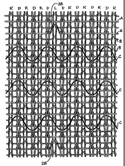
In accordance with the present invention, the knitting machine is set up to
feed yarns
of similar size to the different yarn feeders of the circular knitting
machine. Table I (below)
is a chart of the knitting pattern for the fabric illustrated in Figures 2 and
3. The columns
represent the positions of the regular-butt cylinder needles R, the low-butt
cylinder needles L,
and the dial needles D, respectively, as the cylinder is rotated past each
feed. The knit pattern
repeats on 20 feeds, as shown. Each row in the chart represents a feed. The
character of the
yarn at each feed is represented for convenience by the reference A or B,
although in the
embodiment shown in Figures 2 and 3, A and B are similar yarns. As will be
discussed
below, the A and B yarns may be of different sizes and types, depending upon
the features
desired in the final composite fabric.
The dial needles knit yarn from the odd numbered feeds, alternately. The
cylinder
~5 needles, on the other hand, knit with the yarns at the even numbered feeds
throughout the 20-
WINSTON l263741v4
CA 02491450 2004-12-24
course repeat. The stitches produced by this pattern are diagraznmammatically
illustrated in Figure
3. Each yarn (A, B) extends generally parallel to the other yarns, producing a
single
coursewise row of loops within the repeat. The regular butt needles form wales
R in the
fabric, the low butt cylinder needles form wales L, and the dial needles form
wales D. In
setting up the machine, in each set of 12 cylinder needles, there rnay be a
single low butt . .
needle, and the remainder will be regular butt needles so that the tuck
stitches are knitted in
every twelfth cylinder wale.
Table I
Feed Number Regular ButtLow Butt Dial NeedlesYam Type
Cylinder Cylinder
Needles Needles
1 Welt Tuck Knit A
2 Knit Knit Welt B
3 Welt Welt Knit A
4 Knit Knit Welt B
5 Welt Welt Knit A
b Knit Knit Welt B
7 Welt Welt Knit A
8 Knit Knit Welt B
9 Welt Welt Knit A
14 Knit Knit Welt B
11 Welt Welt Knit A
12 Knit Knit Welt B
_ 6
W WSTON i 263741 v4
CA 02491450 2004-12-24
13 Welt Welt Knit A
14 Knit Knit Welt B
15 Welt Welt Knit A
16 Knit Knit Welt B
17 Welt Welt Knit A
18 Knit Knit Welt B
19 ~ Welt Welt Knit A
20 Knit Knit Welt B .
21 Welt Tuck Knit A
22 Knit Knit Welt B
23 Welt Welt Knit A
24 Knit Knit Welt B
25 ~ Welt Welt Knit A
26 Knit Knit Welt B
27 Welt Welt Knit A
28 Knit Knit Welt B
29 Welt Welt Knit A
30 Knit Knit Welt B
31 Welt Welt Knit A
32 Knit Knit Welt B
33 Welt Welt Knit A
34 Knit Knit Welt B
35 Welt Welt Knit A
r
s
36 Knit Knit . Welt B
37 Welt Welt Knit A
WIrISTON 1263741v4
CA 02491450 2004-12-24
3g __ _ _ fit Knit Welt - -
39 Welt Welt Knit A
40 Knit Knit Welt B
In one embodiment, the outer ply 22 is desirably formed of cotton yarns
between 2611
and 12/1, although the invention is not limited thereto. The outer ply 22 may
alternatively
have an even feed of a different type of yarn or yam size, although when
similarly sized yarns
are used, the outer ply 22 provides a smooth and neat appearance. Other
natural or synthetic-
fiber yarns may be substituted to produce any special features that may be
desired in the outer
ply 22. The inner ply 26 also comprises cotton yarns between 26/1 and 12/1.
The
interconnected plies 22, 26 ultiraately provide an air entrapment barrier to
the inside channel
formed between the inner and outer plies.
l0 In a second embodiment, the inner ply 26 is fbrmed of hydrophilic yams,
such as
cotton, to promote the movement of moisture away from a wearer of a garment
formed from
the composite fabric. The outer ply 22 is then formed of hydrophobic yarns,
such as
polyester or nylon, to provide a water-repellent exterior. As those skilled in
the art will
appreciate, there are numerous possible combinations of yarn types and sizes.
1 s At least one channel-opening yarn C is inserted between the two overlying
webs
during the knitting operation. In one embodiment, the yarn, or yarns, may be
cotton,
polyester, nylon, or rayon between 36/1 and 14/1. The channel-opening yarn C
is held
substantially in parallel relation to the parallel lengths of yam forming each
of the two
overlying webs. Specifically, the channel-opening yarn C is inserted under
tension during the
2o knitting operation. At the completion of the knitting operation, when the
fabric and channel-
opening yarn is permitted to relax, the channel-opening yarn C causes the
confronting webs
W1NSTON 1263741x4
CA 02491450 2004-12-24
to be spaced apart within each of the channels between the tuck stitches. As
shown in
Figures 2 and 3, when the fabric is permitted to relax, the channel-opening
yarns C retract
into a sinusoidally-shaped orientation in the coursewise direction. Each yarn
C is fed through
the stop motion of the storage feeder (not amund the feedwheel). The yam is
then pulled in
between the hvo layers of fabric in front of a dial knit feed. The tension of
each feed is
between about 4 gums and 6 grams. This permits a yarn draw of between 94
inches per
revolution and 106 inches per revolution of the cylinder; however, as those
skilled in the art
will appreciate, draw js directly related to the weight per square yard of the
fabric.
The number of channel-opening yarns that are inserted is dependent upon the
spacing,
in courses, between the tuck stitches; however, the number and spacing of the
channel-
opening yarns is not critical to the present invention. The use of the tuck
stitches in
combination with the channel-opening yarns permits both of the overlying webs
to be formed
of the same yarn materials and sizes, and also eliminates the need for
introducing large and
small yarns in the fabric construction so as to create channel openings
otherwise.
With the machine setup for forming the bi-ply fabric construction, certain
settings are
made for laying-inlinserting the one to three strands of channel-opening yams
between the
tucks in the bi-ply fabric. The cap of the knitting machine is raised to a
setting of 0.110
inches to make space for the laid-in yams. The storage feeders for the channel-
opening yams
are mounted between the cylinder tucks for stop motion only.
Another aspect of the present invention is directed to the bi-ply fabric as
described
above wherein the channel-opening yams C are formed of a wire material that is
desirably
conductive. In one embodiment, the wire yams are selected from the group of
metallic yarns
consisting of stainless steel, copper, nichronium and silver; however, the
yams are not limited
thereto so long as they provide suitable electrical conductivity, resistance,
radio frequency
transmission, etc. as required for the intended applications described
hereinbelow. Further,
9
WINS'P01J t2b3741v4
CA 02491450 2004-12-24
the metallic yarns may have outer covers such as silicon encapsulated wire for
ultimate
connection to a silicon microcomputer chip. Depending upon the particular
application, the
wire yarns are between about 27 American Wire Gauge (AWG) and 33 AWG. The wire
yarns may further be braided or tinned and may be coated or uncoated. Suitable
coatings/covers include cotton fabric outer sheathing, polyvinyl chloride
(PVC) coating, or
silicone encapsulation.
In one embodiment, the channel-opening yams C of wire yarns provide two
functions.
First, they provide the channel-opening described above, and secondly, they
provide a
resistance heating structure between the outer 22 and inner 26 plies of
the.fabric construction
io of the present invention. The channel-opening/conductive yams C are
inserted into the fabric
structure in the same manner described above. It has been found that a battery-
powered or
solar-powered resistance temperature device 42, 46 (shown in Figures 4A and
4B) may be
interconnected to the terminal ends of the channel-opening/conductive yarns to
complete the
resistance heating circuit. Such a device is typical of suitable compact
resistance temperature
devices that may easily be inserted into a pocket or pouch 43, 47 and
interconnected via a
connector 41, 45 to the conductive yams. If desired, a thermostatic
controller, or rheostat
(not shown) may be installed in the circuit to provide a wearer with the
ability to regulate the
amount of heat generated by the device 42, 46. Where multiple channel-
opening/conductive
yarns are incorporated into the fabric, and/or where a garment comprises
multiple tubular
pieces of fabric that are seamed together, the free ends of the channel-
opening/conductive
yarns may be joined by conductive flat seam stitches, tacks, conductive
patches, or the like, at
the seams 49a, 49b, 49c.
In a second embodiment, one or more of the channel-opening/conductive yarns C
serve as an antenna for the receipt and transmission of radio frequency (RF)
signals. An
antemia of this type and structure is capable of receiving and transmitting
radio frequency
WWSTON 1263741v4
CA 02491450 2004-12-24
signals for portable devices 42,46 such as cell telephones, wireless digital
devices, etc. that
are capable of transmitting voice and data signals.
In yet another embodiment, the conductive yarns C are connectable to a micro-
computer device such as a global positioning system (GPS), personal digital
assistant (PDA),
etc.
Although tfie present invention has been described with preferred embodiments,
it is
to be understood that modifications and variations may be utilized without
departing from the
spirit and scope of the invention, as those skilled in the axt will readily
understand. Such
modifications and variations are considered to be within the purview and scope
of the
t o appended claims and their equivalents.
11
WWSTON 1263741v4