Note: Descriptions are shown in the official language in which they were submitted.
13DV 1360$1
CA 02491619 2005-O1-06
BIFURCATED OUTLET GUIDE VANES
BACKGROUND OF THE INVENTION
The present invention relates generally to gas turbine engines, and, more
specifically, to
outlet guide vanes therein.
In a gas turbine engine, air is pressurized in a compressor and mixed with
fuel for
generating hot combustion gases from which energy is extracted in turbine
stages. A
high pressure turbine (HPT) immediately follows the combustor and extracts
energy for
powering the compressor. A low pressure turbine (LPT) follows the HPT and
extracts
additional energy from the combustion gases for powering an upstream fan in an
exemplary aircraft turbofan engine application.
Each turbine stage includes a row of nozzle vanes specifically configured for
precisely
directing the combustion gases into a cooperating row of turbine rotor blades
disposed
downstream therefrom. The vanes and blades have specifically configured
aerodynamic
profiles for maximizing energy extraction from the combustion gases, with the
profiles
thereof being opposite to each other and alternating from stage to stage.
From the last turbine stage in the LPT, the combustion gases are exhausted
through
outlet guide vanes (OGVs) typically found in the turbine rear frame
immediately
downstream of the LPT.
The OGVs typically have specific aerodynamic profiles to remove swirl, or
deswirl the
exhaust flow prior to discharge from the engine for enhancing the performance
thereof.
Exhaust swirl is defined as the angle of discharge from the last stage turbine
blades
relative to the axial centerline axis of the engine. The swirl angle will vary
during low
to high power operation of the engine.
The range or swing in swirl angle varies from minimum to maximum values
depending
upon the configuration and operation of the specific engine and may be
relatively small
or relatively large. For small values of swirl range, the individual OGVs may
have
suitable aerodynamic profiles with generally convex suction sides and
generally concave
pressure sides, with a corresponding pitch or angular orientation around the
radial axis
1
13DV 136081
CA 02491619 2005-O1-06
for deswirling the exhaust flow. Deswirling operation of the OGVs remains
effective as
long as the exhaust flow remains attached to the surfaces of the vanes.
In applications containing large swirl range, the specific aerodynamic profile
and
angular orientation of the OGVs may be insufficient to prevent flow separation
from the
vanes at one or both extremes in the range of swirl angles. Since a vane is
typically
optimized for a specific design point, off design point operation of the vane
changes the
aerodynamic performance thereof eventually leading to flow separation at
excess swirl
angles of the exhaust.
Flow separation of the exhaust flow from the OGVs is undesirable since it
destroys the
ability of the vanes to properly deswirl the exhaust flow, and therefore
reduces
aerodynamic performance and efficiency of the engine.
The ability to deswirl exhaust flow is made more difficult in variable cycle
gas turbine
engines such as those specifically configured for short takeoff and vertical
landing
(STOVL) operations. STOVL aircraft are typically used by the military for the
extreme
military requirements thereof. One type of STOVL aircraft includes an
augmented
turbofan engine having an afterburner at the aft end thereof, with a variable
area exhaust
nozzle. The afterburner permits additional fuel to be burned therein for
substantially
increasing the available thrust and power generated by the engine when
required.
Since the afterburner is disposed downstream from the turbine OGVs,
performance of
those vanes is further important to ensure suitably deswirled exhaust flow to
the
afterburner for the proper performance thereof during reheat or wet operation.
Performance of the turbine OGVs is further complicated by the modification of
the
turbofan engine for the STOVL operation which may include an extension of the
fan
drive shaft for powering an auxiliary fan mounted in the aircraft wing for
enhancing
vertical lift. And, bleed tubes may join the turbofan bypass duct for bleeding
therefrom
when desired a portion of the fan air which is diverted to corresponding
nozzles in the
aircraft for providing additional vertical lift capability and stability
control of the aircraft
in the STOVL mode of operation.
2
13DV 136081
CA 02491619 2005-O1-06
Accordingly, this exemplary form of STOVL turbofan engine creates a Iarge
swing or
range in the swirl angle of the exhaust discharged from the core engine
through the
OGVs. In conventional takeoff and landing operation of the engine, the swirl
angle of
the exhaust flow is limited in value and range. Whereas, during the STOVL mode
of
operation of the engine, the swirl angle of the exhaust flow from the core
engine is
substantially changed to large values.
The typical fixed-design deswirling outlet guide vane is thusly severely
limited in its
ability to handle the large range of swirl angle change found in a STOVL
aircraft engine.
It is therefore desired to provide outlet guide vanes specifically configured
for
accommodating large swing in swirl without undesirable flow separation
therein.
BRIEF DESCRIPTION OF THE INVENTION
A turbine rear frame includes a row of outlet guide vanes extending between
outer and
inner bands. Each of the vanes is bifurcated into a forward prow integrally
joined to an
aft stern by a septum therebetween. The prow and stern collectively define the
aerodynamic profile of each vane which is locally internzpted at the septum.
BRIEF DESCRIPTION OF THE DRAWINGS
The invention, in accordance with preferred and exemplary embodiments,
together with
fiu-ther objects and advantages thereof, is more particularly described in the
following
detailed description taken in conjunction with the accompanying drawings in
which:
Figure 1 is an axial schematic view of an exemplary STOVL turbofan aircraft
engine
including a row of outlet guide vanes at the discharge end of the core engine
thereof.
Figure 2 is a partly sectional, isometric view of a portion of the OGVs
illustrated in
Figure 1 in accordance with an exemplary embodiment.
Figure 3 is a planiform sectional view through some of the OGVs illustrated in
Figures 1
and 2 located immediately downstream of the Iast stage turbine blades.
Figure 4 is a planiform sectional view, like Figure 3, of the OGVs in
accordance with
3
13DV 136081
another embodiment.
CA 02491619 2005-O1-06
Figure 5 is a planiform sectional view, like Figure 3, of the OGVs in
accordance with
another embodiment.
Figure 6 is a planiform sectional view, like Figure 3, of the OGVs in
accordance with
another embodiment.
DETAILED DESCRIPTION OF THE INVENTION
Illustrated schematically in Figure 1 is a turbofan gas turbine engine 10
specifically
configured for powering a STOVL aircraft in an exemplary application. The
engine is
axisymmetrical about a longitudinal or axial centerline axis and includes in
serial flow
communication a fan 12, multistage axial compressor 14, combustor 16, high
pressure
turbine (HPT) 18, and low pressure turbine (LPT) 20. The HPT 18 is j oined to
the
compressor 14 by one shaft, and the LPT 20 is joined to the fan 12 by another
shaft.
During operation, air 22 enters the engine and is pressurized in the
compressor 14 and
mixed with fuel in the combustor 16. The aspirated air is ignited for
generating hot
combustion gases 24 which are discharged in turn through the HPT 18 and LPT 20
that
extract energy therefrom. The HPT powers the compressor, and the LPT powers
the
fan.
In the exemplary STOVL configuration illustrated in Figure 1, the engine also
includes
an augmentor or afterburner 26 in which additional fuel may be burned when
desired for
increasing the exhaust thrust from the engine. A variable area nozzle 28 is
located at the
aft end of the afterburner and cooperates therewith for maximizing performance
of the
engine over its intended flight envelope.
For the STOVL application, the engine 10 illustrated in Figure 1 further
includes an
auxiliary fan 30 operatively joined to the main fan 12 by a drive shaft
extension thereof.
And, large bleed tubes 32 are joined in flow communication to the upstream end
of the
bypass duct surrounding the core engine for bleeding a portion of the fan air
therefrom
when desired.
4
13DV 136081
CA 02491619 2005-O1-06
The STOVL engine 10 illustrated schematically in Figure 1 may have any
conventional
configuration and operation for operating in a conventional mode without the
use of the
auxiliary fan 32 and bleed tubes 32, and in a STOVL mode of operation in which
the
auxiliary fan 30 is powered by the engine, and fan air is bled from the engine
through the
tubes 32 to suitable nozzles in the aircraft for providing additional lift and
stability
control thereof during operation. However, the STOVL capability of the engine
10
illustrated in Figure 1 results in a substantial range or swing in swirl
angles of the
exhaust flow 24 discharged from the LPT 20 during operation into the augmentor
26.
Accordingly, the engine includes a turbine rear frame 34 specifically
configured for
accommodating the extended range in swirl angle for this type of engine
without the
need for mechanical articulation thereof which would otherwise increase
complexity and
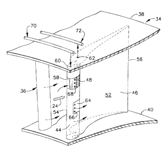
weight of the engine. The rear frame 34 is illustrated isometrically in part
in Figure 2
and in planiform view in part in Figure 3 in accordance with an exemplary
embodiment.
The rear frame is an annular assembly of components and is axisymmetrical
about the
longitudinal or axial centerline axis of the engine. The frame includes a
plurality of
outlet guide vanes (OGVs) 36 arranged in a circumferential row extending
radially
between outer and inner supporting bands 38,40.
As shown in Figure 3, the vanes 36 are disposed immediately downstream of the
last
stage row of turbine rotor blades 42 found in the LPT, and which extend
radially
outwardly from their supporting rotor disk. During operation, the exhaust flow
24 is
discharged from the turbine blades 42 with a suitable swirl angle A which is
measured
relative to the axial centerline axis of the engine, toward the OGVs.
The swirl angle of the exhaust flow varies from a maximum positive value
represented
by the angle A to a corresponding minimum value represented by the negative
swirl
angle -B. For example, the maximum swirl angle may be about +40 degrees, and
the
minimum swirl angle may be about -20 degrees, with a combined range or swing
of
swirl being the 60 degree combination thereof.
The large range in swirl angle is specifically due to the variable cycle
configuration of
the STOVL engine 10 illustrated in Figure 1. During normal operation of that
engine,
S
13DV 136081
CA 02491619 2005-O1-06
the turbofan engine operates in the normal manner of a turbofan engine with
the core
exhaust flow and the bypass air being discharged through the augmentor to the
common
outlet nozzle. And, during STOVL operation of the engine, the fan bypass flow
around
the core engine is temporarily interrupted by a suitable valve to divert fan
air through the
bleed tubes 32, while the auxiliary fan 30 is engaged for diverting
corresponding power
from the engine.
In this STOVL operation of the engine, the swirl angle of the exhaust flow 24
is
drastically altered from its normal range as the exhaust flow is nevertheless
discharged
between the OGVs 36 into the augmentor.
In order to accommodate the large range in swirl angle of about 60 degrees,
and even
larger, the OGVs 36 illustrated in Figure 3 are bifurcated in a specific
manner for
accommodating the large change in direction of the incident exhaust flow.
More specifically, each of vanes 36 illustrated in Figure 3 is bifurcated into
a forward
prow or nose segment 44 and an aft stern or tail segment 46 by a narrow septum
48
extending chordally or axially therebetween. The prow and stern are an
integral, and
preferably unitary assembly and collectively define the aerodynamic profile or
perimeter
of each vane 36 with a convex suction side 50 and a circumferentially
opposite, concave
pressure side 52. The two sides 50,52 extend chordally between a leading edge
54 at the
front of the prow 44 and an axially opposite trailing edge 56 at the aft end
of the stern
46.
As shown in Figure 3, the combined configuration of the prow and stern
includes a
chord extending between the leading and trailing edges thereof which may be
located at
a suitable pitch angle C relative to the axial centerline axis of the engine.
The
aerodynamic contour of the vanes 36 is generally opposite to the contours of
the last
stage turbine blades 42, and have a suitable pitch angle C for maximizing the
deswirling
capability of the vanes corresponding with the maximum expected swirl angle
from the
blades in the preferred embodiment.
Since the prow and stern illustrated in Figure 3 are separated from each other
by the
joining septum or ligament 48, these two portions of each vane may be
separately
6
13DV 136081
CA 02491619 2005-O1-06
tailored in profile while still collectively providing the overall aerodynamic
profile of the
vane. The overall profile of the vane is locally interrupted chordally between
the prow
and stern at the septum therebetween. The septum 48 is relatively narrow
across the
width of the vane between its opposite sides, and introduces a first radial
slot 58 which
separates in part the prow from the stern. The septum 48 itself is preferably
imperforate.
The stern 46 illustrated in Figure 3 defines the major portion of each vane
having the
greatest amount of chordal length, whereas the prow 44 is relatively short in
chordal
length for the remaining minor portion of each vane. The prow 44 defines the
leading
edge portion of each vane, and the stern 46 converges aft to the trailing edge
56 from its
junction with the forward prow at the septum 48. In this way, the prow shields
the
forward end of the stern and cooperates therewith as further described
hereinbelow for
substantially increasing the range of permissible swirl angle without
undesirable flow
separation of the exhaust flow over the vanes during operation.
The vanes illustrated in Figure 3 are hollow at least in part and include in
this exemplary
embodiment an internal prow channel 60 extending radially through the prow,
and a
corresponding internal stern channel 62 extending radially through the stern.
The two
internal channels 60,62 in each vane preferably extend through the outer band
38 as
illustrated in Figure 2 for providing flow communication therethrough.
The first radial slot 58 illustrated in Figure 3 is disposed between the prow
and stern on
the suction side of the vane. A second radial slot 64 is disposed in the prow
44 itself on
the opposite pressure side of the vane forward of the septum 48. In this way,
the prow
and stern may be specifically configured for introducing the two radial slots
58,64 on
opposite sides thereof immediately downstream of the leading edge.
A row of prow apertures 66 is disposed through the pressure sidewall thereof
in flow
communication with the prow channel 60 on one side and the second radial slot
64 on
the opposite side, which slot is fed by the prow channel 60.
Correspondingly, a row of stern apertures 68 is disposed in the front wall of
the stern
adjacent to the imperforate septum 48 for providing flow communication between
the
stern channel 62 and the first radial slot 58, which slot feeds the stern
channel. In this
7
13DV 136081
CA 02491619 2005-O1-06
way, the two slots 58,64 cooperate with the respective internal channels in
the stern and
prow in flow communication through the outer band 38 illustrated in Figure 2.
As shown in Figures 1 and 2, suitable means 70 are provided for supplying
pressurized
air 22 into the row of hollow vanes 36 for discharge through the prow
apertures 66 into
the corresponding prow slots 64. For example, the pressurized air may be bled
from the
compressor 14 or fan 12 by suitable conduits having flow control valves
therein to
distribute the pressurized air through an annular manifold surrounding the
outer band 38
into each of the vanes 36 suitably joined thereto.
In this way, a common supply manifold is joined in flow communication to each
of the
prow channels 60 through the outer band for providing pressurized air into the
prow.
The pressurized air may then be discharged through the second slots 64, on the
pressure
side of the vanes for example, to promote and maintain attachment of the
exhaust flow
over the vane.
Correspondingly, Figures 1 and 2 illustrate additional means 72 for
withdrawing the
exhaust flow 24 from the exemplary first slots 58 disposed on the suction side
of the
vanes as illustrated in Figure 3. As the exhaust flows over the vane suction
sides during
operation, a portion thereof is extracted or withdrawn through the stern
apertures 68 and
into the stern channel 62 for discharge through the outer band.
As shown in Figures 1 and 2, the withdrawing means 72 may include another
annular
manifold surrounding the outer band and disposed in flow communication with
the
corresponding stern channels 62 in each of the vanes for extracting exhaust
flow
therefrom. The withdrawing manifold may be simply vented to the atmosphere
externally of the engine. During aircraft flight, the pressure outside the
engine is
substantially lower than the pressure inside the engine of the exhaust flow
between the
outlet guide vanes, and the atmosphere provides a suitable sink for
withdrawing exhaust
flow from the vanes.
The exemplary first slots 58 therefore draw the exhaust flow over the suction
side of the
prow for maintaining flow attachment thereto and preventing undesirable flow
separation of the exhaust as it flows downstream over the suction side of the
stern
8
13DV 136081
during operation.
CA 02491619 2005-O1-06
Figure 3 illustrates one embodiment of the bifurcated vanes 36 with
specifically
configured prow 44 and stern 46. The introduction of the suction side radial
slot 58
interrupts the axial continuity of the vane suction side, and correspondingly
introduces a
locally small convex suction side on the prow itself leading into the slot 58.
The convex
profile of the prow itself may be used for enhancing flow attachment of the
exhaust flow
thereover as well as over the remaining suction side of the vane over the
stern.
In this way, the bifurcated vane may be designed to handle the large range of
swirl
angles found in the STOVL aircraft engine without requiring articulation or
repositioning of the vane itself, and the associated complexity thereof. The
stern
channel 62 may be simply vented outside the engine so that a portion of the
exhaust
flow over the vane suction side is withdrawn through the first slot 58 for
enhancing flow
attachment notwithstanding large variation in the swirl angle.
Correspondingly, the second slot 64 receives pressurized air from the prow
channel 60
and discharges that air in a thin film aft along the pressure side of the vane
for enhancing
flow attachment of the exhaust flow thereover.
The different configurations of the prow 44 and stern 46 and the associated
slots 58,64
permit various permutations thereof which may be used to advantage in
increasing the
range of swirl angle while reducing or avoiding undesirable flow separation
over the
vanes during operation. Figure 3 illustrates one embodiment, and Figures 4, S,
and 6
illustrate alternate embodiments in which common features are identified by
common
reference numerals, and suitably modified for the different embodiments. Since
the
prows and sterns have modified configurations in Figures 4-6, they themselves
are
differently numbered, notwithstanding the otherwise similar features and
operation
thereof.
For example, the first, or suction-side, slot 58 illustrated in Figure 3 faces
forward
toward the leading edge in the vane suction side 50 for collecting a portion
of the
exhaust flow therein for discharge through the outer band. In Figure 4, the
modified
prow 74 is similarly configured for introducing the forward facing first slot
58. And, in
9
13DV 136081
CA 02491619 2005-O1-06
Figure S the modified prow 78 is also similarly configured for introducing the
forward
facing first slot 58.
In the alternate embodiments illustrated in Figures 3, 4, and 5, the prows and
sterns
therein are spaced chordally apart at the corresponding first slots 58 in the
suction sides
to provide unobstructed open access to those slots for fi~eely receiving the
exhaust flow.
Correspondingly, the suction side portions of those differently configured
prows
44,74,78 have locally convex profiles for maintaining flow attachment of the
incoming
exhaust flow irrespective of the large range in swirl angles.
Figure 6 illustrates that the first slot 58 in the suction side of the vane
may alternatively
face aft toward the trailing edge, with the corresponding prow 82 including a
lip 86
extending aft over most of the first slot 58.
Figure 5 illustrates that the second slot 64 in the vane pressure side 52 may
alternatively
face forward toward the leading edge 54 for collecting the exhaust if desired.
And, the
prow 78 and stern 80 are spaced chordally apart at the forward facing slot 64
to provide
unobstructed open access thereto.
Figures 4 and 6 illustrate additional modifications in which the second slot
64 faces aft
toward the trailing edge in the vane pressure side 52. And, additional lips 86
extend aft
over the corresponding second slots 64 to provide smooth transitions between
the
corresponding prows and sterns.
Figures 4-6 illustrate exemplary embodiments in which the corresponding
septums 48
thereof are spaced inwardly from both sides of the vanes to introduce opposite
radial
slots 58,64 therein.
In the Figure 5 embodiment, the two slots 58,64 are similarly configured in
the
corresponding suction and pressure sides 50,52 of the vane, and both face
forward
toward the leading edge without flow obstruction. In this embodiment, the prow
78 is
solid without any internal flow channel, and the stern 80 alone includes the
stern channel
62 and two rows of the stern apertures 68 corresponding with the two radial
slots 58,64
in the opposite sides of the vane. In this way, corresponding portions of the
exhaust
10
13DV 136081
CA 02491619 2005-O1-06
flow 24 may be withdrawn from both sides of the vane just aft of the leading
edge for
promoting flow attachment on both sides of the vane notwithstanding the large
swing in
swirl angle.
Figure 6 illustrates yet another embodiment in which the two slots 58,64 in
the opposite
suction and pressure sides 50,52 of the vane both face aft toward the trailing
edge, with
each slot including a corresponding lip 86 for maintaining an aerodynamically
smooth
junction between the prow 82 and stern 84.
In this embodiment, the stern 84 immediately aft of the septum 48 may be solid
without
the internal stern channel therein, and the prow 82 includes a common prow
channel 60
for feeding both radial slots 58,64 through corresponding rows of the prow
apertures 66.
The prow 82 including the aft lips 86 thereof may be specifically configured
in profile
for enhancing flow attachment of the exhaust flow during operation, with flow
attachment being further enhanced by the discharge of pressurized air from the
two slots
58,64 during operation.
Figure 4 illustrates yet another embodiment in which the two slots 58,64 are
disposed on
opposite sides of the common septum 48. The first slot 58 of the vane suction
side 50
faces forward toward the leading edge without obstruction, and the second slot
64 in the
vane pressure side 52 faces aft toward the trailing edge, and covered in most
part by the
lip 86. The lip 86 in this embodiment overlaps the pressure side of the stern
76, and is
not aligned flush therewith in the manner illustrated in the Figure 6
embodiment.
In the Figure 3 embodiment, the septum 48 is spaced inwardly from only the
vane
suction side 50 and adjoins the vane pressure side 52. And, the first radial
slot 58 in the
vane suction side faces forward, whereas the second slot 64 in the prow
pressure side 52
faces aft toward the trailing edge.
In the Figure 3 embodiment, the prow 44 itself includes the second slot 64
facing aft in
the pressure side of the vane upstream from the septum 48. And, in the
alternate
embodiments illustrated in Figures 4 and 6, the aft-facing second slot 64 is
located at the
septum 48 itself under the aft lip extension 86 of the prow.
11
13DV 136081
CA 02491619 2005-O1-06
But for the two rows of prow and stern apertures 66,68 which provide flow
communication between the respective slots 58,64 and prow and stern channels
60,62,
the various embodiments of prows and sterns are otherwise imperforate for
maintaining
aerodynamically smooth contours of the bifurcated vanes.
In the several embodiments illustrated in Figures 3-6, the prows and sterns
may be
formed together in a common casting in view of the complex configuration
thereof. The
internal channels, apertures, and slots may also be conveniently formed by
conventional
casting.
The aft portions of the various sterns illustrated in Figures 3-6 are
preferably
manufactured as separately fabricated sheet metal components and suitably
joined to the
corresponding castings by brazing for example. Alternatively, the entire
bifurcated vane
may be cast in one unitary component, or could alternatively be a fabrication
of sheet
metal parts integrally joined together in a one-piece component or assembly.
The various embodiments of the bifurcated outlet guide vanes illustrated in
the several
figures introduce corresponding prows and sterns separated by radial slots in
the
corresponding sides of the vanes. The prow may be separately configured for
maximizing aerodynamic performance thereof based on the particular incident
angle of
exhaust flow, with the corresponding sterns being separately configured for
maintaining
flow attachment of the exhaust flow during the deswirling process.
The slots in the pressure and suction sides of the vanes may be configured for
discharging pressurized air along the corresponding vane side or withdrawing a
portion
of the exhaust flow for maintaining flow attachment without undesirable flow
separation
during operation. Pressurized air may be introduced on one or both sides of
each vane;
or the exhaust flow may be withdrawn from one or both sides of each vane; or
air may
be supplied on one side while exhaust flow is withdrawn on the other side of
each vane
as desired for maximizing performance.
The corresponding means for supplying pressurized air or withdrawing exhaust
flow
from the outlet guide vanes may be suitably coordinated using flow control
valves under
computer control for best coordinating operation of the vanes with operation
of the
12
13DV 136081
CA 02491619 2005-O1-06
engine from the normal mode of operation to the STOVL mode of operation during
which the swirl angle of the exhaust flow discharged from the core engine
swings over a
substantially large range, such as the 60 degrees range disclosed above, or
even higher.
While there have been described herein what are considered to be preferred and
exemplary embodiments of the present invention, other modifications of the
invention
shall be apparent to those skilled in the art from the teachings herein, and
it is, therefore,
desired to be secured in the appended claims all such modifications as fall
within the
true spirit and scope of the invention.
13