Note: Descriptions are shown in the official language in which they were submitted.
CA 02491659 2005-O1-04
WO 2004/008025 PCT/US2003/021800
MOUNTING BRACKET, AND METHOD THEREFOR
BACKGROUND OF THE INVENTION
1) Field of the Invention
The present invention relates to overhead fixtures and, more particularly, to
mounting brackets for overhead fixtures.
2) Description of Related Art
There are currently available a wide variety of overhead or ceilW g-mounted
light fixtures, such as chandeliers, which extend from the ceiling of a room.
When
installing a ceiling-mounted light fixture, the light fixture must be attached
to the
ceiling support structure, i.e., joist(s), to insure that the light fixture is
secure. In
this regard, an opening typically is made in the ceiling, which can be formed
of
drywall, plaster or a similar material. An electrical junction box is
typically
mounted within the opening to one or more ceiling joists) using fasteners,
such as
nails or screws, so that the bottom edge of the electrical junction box is
flush with
the ceiling. Electrical wiring is then wired into the electrical junction box
so that it
can be connected to wires from the light fixture.
To mount a light fixture, a conventional mounting bracket is secured to the
bottom edge of the electrical junction box using fasteners, such as screws or
bolts.
Conventional mounting brackets typically comprise a planar piece of metal that
includes a threaded aperture for receiving a hollow threaded stem or nipple.
Once
the stem is threaded into the aperture in the bracket, a nut can be placed
onto each
end of the stem and tightened against the corresponding side of the bracket to
insure that the stem is securely fastened to the bracket. The support member
and
-1-
CA 02491659 2005-O1-04
WO 2004/008025 PCT/US2003/021800
light fixture are then raised toward the stem so that the wiring of the light
fixture
can be threaded through the stem. To secure the light fixture to the mounting
bracket, the support member of the light fixture is attached to the end of the
stem,
such as by threading the support member onto the stem, while the installer
supports
the weight of the light fixture. The wiring of the light fixture is then
connected to
the wiring in the electrical junction box. A canopy is then secured to the
support
member using a decorative locking nut to cover the aperture and conceal the
electrical junction box, wiring and mounting bracket.
When mounting a light fixture to a conventional mounting bracket, the
installer must use two hands such that one hand is supporting the light
fixture
while the other hand is inserting the wiring of the light fixture through the
stem
and, thereafter, threading the support member of the light fixture onto the
stem.
Since the installer must use two hands, installing and uninstalling ceiling-
mounted
light fixtures using conventional mounting brackets can be a difficult, if not
dangerous task, particularly if the installer is working from a stool or
ladder. In
addition, adjusting the height of an overhead light fixture installed using a
conventional mounting bracket generally requires that the entire light fixture
be
disassembled.
Thus, there exists a need for an improved mounting bracket for an overhead
light fixture. The improved mounting bracket should simplify the installation
of
overhead light fixtures and should provide a secure engagement with improved
lateral support in comparison to conventional mounting braclcets.
BRIEF SUMMARY OF THE INVENTION
The present invention provides a bracket for attachment to a support for
mounting a fixture, and method for installing the same. According to one
embodiment, the bracket includes a base having first and second sides. The
bracket also includes first and second flanges extending from the first side
of the
base. The first and second flanges define an elongate aperture therebetween.
The
elongate aperture further extends from the first side of the base towards the
second
side of the base. The elongate aperture is adapted to movably receive one end
of
the fixture so that the fixture may be mounted to, and demounted from, the
bracket
-2-
CA 02491659 2005-O1-04
WO 2004/008025 PCT/US2003/021800
by moving the end of the fixture at least partially along the length of the
elongate
aperture and wherein the first and second flanges are structured to contact
the
support to provide lateral support to the bracket and the fixture. In one
embodiment, the base and the first and second flanges are integrally formed.
In
another embodiment, the base and the first and second flanges are formed of
steel.
In yet another embodiment, the first and second flanges extend from the base
at
least partially towards the second side of the base so as to define an acute
angle
between the base and each of the first and second flanges. In yet another
embodiment, the bracket includes a third flange extending from the second side
of
the base. According to one embodiment, the third flange extends from the
second
side of the base at least partially towards the first side of the base so as
to define an
acute angle between the base and the third flange. The third flange is
preferably
structured to contact the support and provide lateral support to the bracket
and
fixture.
In another embodiment, the present invention provides a mounting system
for attaching a fixture to a support. The mounting system includes a connector
having first and second ends. The first end of the connector is structured for
attachment to the fixture. In one embodiment, the connector comprises an
elongate
threaded portion extending at least partially between the first and second
ends of
the connector. The connector can include an expanded portion disposed at the
second end of the connector and a fastener defining an aperture therethrough
structured to threadingly engage the elongate threaded portion. The fastener
is
disposed adjacent to the expanded portion and is adjustable relative thereto
along
the length of the threaded portion.
The mounting system also includes a bracket comprising a base having first
and second sides. The bracket also includes first and second flanges extending
from the first side of the base. The first and second flanges define an
elongate
aperture therebetween. The elongate aperture further extends from the first
side of
the base towards the second side of the base. The elongate aperture is adapted
to
movably receive the second end of the connector so that the fixture may be
mounted to, and demounted from, the bracket by moving the second end of the
connector at least partially along the length of the elongate aperture and
wherein
-3-
CA 02491659 2005-O1-04
WO 2004/008025 PCT/US2003/021800
the first and second flanges are structured to contact the support to provide
lateral
support to the bracket and the fixture. Other variations of the bracket are
discussed
above.
The present invention also provides a method of attaching a fixture to a
support. According to one embodiment, the method includes attaching a bracket
to
a support, the bracket comprising a base having first and second sides and
first and
second flanges extending from the first side of the base, the first and second
flanges defining an elongate aperture therebetween, the elongate aperture
further
extending from the first side of the base towards the second side of the base,
and
wherein the first and second flanges are structured to contact the support to
provide
lateral support to the bracket and the fixture. One end of a fixture is moved
at least
partially along the length of the elongate aperture so that the fixture is
mounted to
the bracket. The end of the fixture is then secured to the bracket. In one
embodiment, the securing step includes threading a fastener along a threaded
portion of a connector so that the fastener secures at least a portion of the
bracket
between the fastener and an expanded portion of the connector. In another
embodiment, the method includes connecting the electrical wiring from the
fixture
to the electrical wiring at the support. In yet another embodiment, one end of
the
fixture is moved at least partially along the length of the elongate aperture
so that
the fixture is demounted from the bracket.
BRIEF DESCRIPTION OF THE SEVERAL VIEWS OF THE DRAWINGS
The foregoing and other advantages and features of the invention, and the
manner in which the same are accomplished, will become more readily apparent
upon consideration of the following detail description of the invention taken
in
conjunction with the accompanying drawings, which illustrate preferred and
exemplary embodiments and which are not necessarily drawn to scale, wherein:
Figure 1 is a perspective view illustrating a mounting bracket, according to
one embodiment of the present invention;
Figure 2 is a plan view illustrating the mounting bracket of Figure 1;
Figure 3 is a plan view illustrating the mounting bracket of Figure 1;
Figure 4 is an elevation view illustrating the mounting bracket of Figure 1;
-4-
CA 02491659 2005-O1-04
WO 2004/008025 PCT/US2003/021800
Figure 5 is an elevation view illustrating the mounting bracket of Figure 1;
Figure 6 is an elevation view illustrating the mounting bracket of Figure l;
Figure 7 is a perspective view illustrating the mounting bracket of Figure 1
attached to a junction box, according to one embodiment of the present
invention;
Figure ~ is an elevation view illustrating a connector, according to one
embodiment of the present invention;
Figure 9 is a perspective view illustrating the connector of Figure 7 being
mounted onto the mounting bracket of Figure 1, according to one embodiment of
the present invention;
Figure 10 is a perspective view illustrating the connector and mounting
bracket of Figure 9 with the connector mounted onto the mounting bracket;
Figure 11 is an elevation view illustrating the connector and mounting
bracket of Figure 10; and
Figure 12 is a perspective view illustrating the connector and mounting
bracket of Figure 9 securing a fixture to a junction box.
DETAILED DESCRIPTION OF THE INVENTION
The present invention now will be described more fully hereinafter with
reference to the accompanying drawings, in which some, but not all embodiments
of the invention are shown. Indeed, this invention may be embodied in many
different forms and should not be construed as limited to the embodiments set
forth
herein; rather, these embodiments are provided so that this disclosure will
satisfy
applicable legal requirements. Lilce numbers refer to like elements
throughout.
Refernng to Figure 12, there is illustrated a mounting system 10, according
to one embodiment of the present invention. The mounting system 10 includes a
bracket 12 for attaching overhead fixtures 14 to a support 16, which provides
greater lateral support to the bracket and fixture and simplifies
installation,
removal, and height adjustment in comparison to conventional mounting
brackets.
The fixture 14 preferably includes an overhead light fixture, such as a
chandelier or
other light fixture that can be suspended using a hanging device, such as
cordage,
chains or elongate rods. However, fixture 14 is not limited to light fixtures,
but
-5-
CA 02491659 2005-O1-04
WO 2004/008025 PCT/US2003/021800
can also include other ornamental, artistic or aesthetic items such as
pictures,
plants, baskets, etc.
Referring to Figures 1-5, the bracket 12 includes a base 18 having first and
second sides 16a,16b. The base 18 can be configured as necessary depending on
the configuration of the support 16, but preferably comprises a planar web
portion.
According to the illustrated embodiment, the bracket 12 includes three flanges
20a,
20b, 20c extending from the base 18. The first and second flanges 20a, 20b
extend
from the first side 18a of the base 18 and the third flange 20c extends from
the
second side 18b of the base. According to one embodiment, as illustrated in
Figures 2 and 6, the first and second flanges 20a, 20b extend from the first
side
18a of the base 18 at least partially towards the second side 18b of the base
and the
third flange 20c extends from the second side 18b of the base at least
partially
toward the first side 18a of the base so that each flange forms an acute angle
with
the base. Advantageously, the acute angle of the flanges 20a, 20b, 20c
prevents
the fixture 14 from becoming inadvertently dislodged from the bracket 12. In
other embodiments (not shown), the flanges 20a, 20b, 20c can be disposed
perpendicular to the base 18 or at an obtuse angle.
Preferably, the flanges 20a, 20b, 20c are formed integrally with the base
18, but the flanges can be formed separately and then attached to the base
using
mechanical fasteners or welding (not shown). The bracket 12 can be formed of a
variety of materials, including, but not limited to, steel or other metals or
composite materials, provided the materials have sufficient strength and, if
necessary for outdoor applications, corrosion resistance for the particular
applications contemplated.
Referring to Figures 2 and 3, the base 18 of the bracket 12 defines a pair of
apertures 22 adapted to receive corresponding fasteners 24. As illustrated in
Figure 7, the fasteners 24 can comprise screws, bolts or the like. The
fasteners 24
are used to secure the bracket 12 to the support 16, which can include one or
more
joists or other framing members (not shown) or, as illustrated in Figure 7, an
electrical junction box 26. Referring to Figure 7, the angled flanges 20a,
20b, 20c
extend into the electrical junction box 26 when the bracket 12 is mounted to
the
box. Advantageously, since at least a portion of each of the angled flanges
20a,
-6-
CA 02491659 2005-O1-04
WO 2004/008025 PCT/US2003/021800
20b, 20c is in contact with a side of the electrical junction box 10, the
bracket 12 of
the present invention has greater lateral support than a conventional planar
mounting bracket. In addition, because the bracket 12 of the present invention
has
a greater load bearing surface area than a conventional planar mounting
bracket,
there is a reduction in the stress applied to the bracket 12 when supporting a
fixture
14 so that the bracket of the present invention can support heavier fixtures.
In
other embodiments of the invention (not shown) where the flanges 20a, 20b, 20c
are disposed perpendicular to the base 18 or at an obtuse angle to the base,
the
flanges 20a, 20b, 20c of the bracket 12 preferably will extend from the base
18 so
that the flanges will at least partially contact the support to provide
improved
lateral support to the bracket 12 and fixture 14.
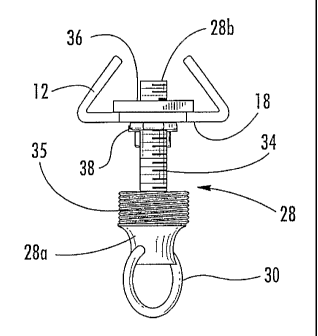
Referring to Figures 8 and 12, the mounting system 10 includes a connector
28 having first and second ends 28a, 28b. The first end 28a of the connector
28 is
structured for attachment to the fixture 14. For example, certain overhead
fixtures
14 are suspended using hanging devices, such as cordage, chains, or elongate
rods.
According to one embodiment of the present invention, as illustrated in
Figures 11
and 12, the first end 28a of the connector 28 includes a ring, loop or hook 30
that is
structured to be connected to the hanging device 32 that is used to suspend
the
fixture 14. For example, as illustrated in Figure 12, a chain 32 extending
from the
fixture 14 can be secured to the ring 30 of the connector 28 using a quick-
link
chain member 31, as is well known in the art. In other embodiments (not
shown),
the first end 28a of the connector 28 can define a threaded portion that
engages a
corresponded threaded aperture defined by the end of the fixture 14 or,
alternatively, the first end 28a of the connector 28 can be welded or formed
integrally with the fixture.
According to one embodiment of the present invention, as illustrated in
Figure 8, the connector 28 includes an elongate threaded portion or stem 34
extending at least partially between the first and second ends 28a, 28b of the
connector. The stem 34 is threaded into a threaded aperture defined by the
bottom
member 35. Alternatively, the stem 34 can be formed integrally with, or be
welded
to, the bottom member 35.
CA 02491659 2005-O1-04
WO 2004/008025 PCT/US2003/021800
The connector 28 also includes an expanded portion or flange 36 disposed
generally at the second end 28b of the connector. For example, as illustrated
in
Figure 8, the expanded portion 36 can include a rectangular nut or fastener
defining a threaded aperture therethrough structured to engage the threads
defined
by the stem 34. Alternatively, the expanded portion 36 can include a nut or
other
fastener secured to a washer (not shown), which can be threaded unto the stem
34
of the connector 28.
The connector 28 can further include a fastener 38 defining a threaded
aperture therethrough structured to engage the threads defined by the elongate
threaded portion 34. The fastener 38 is disposed adjacent to the expanded
portion
36 and is adjustable relative thereto along the length of the threaded portion
34. As
discussed in more detail below, the fastener 38 and expanded portion 36 are
used
to secure the connector 28 to the bracket 12.
As illustrated in Figures 1-4, the bracket 12 defines a slot or elongate
aperture 40, which extends from the distal edge of the first and second
flanges 20a,
20b to approximately the center of the base 18. The slot 40 is structured to
movably or slidably receive an end of the fixture 14, and more specifically,
the
second end 28b of the connector 28 so that the connector does not have to be
threadably secured to the bracket 12. Referring to Figure 8, the stem 34 is
attached to the bottom member 35, if necessary, and the expanded portion 36
and
the fastener 38 are threaded onto the stem 34. The position of the fastener 38
on
the stem 34 is adjusted so that the fastener is adjacent the bottom member 35
to
thereby define a gap between the fastener 38 and the expanded portion 36. The
height of the gap is approximately equal to or greater than the height of the
pair of
the first and second flanges 20a, 20b so that the expanded portion 36 will
extend
over the edge of the pair of flanges as the stem 34 is slid into and along the
length
of the slot 40, as illustrated in Figures 9 and 10. According to one
embodiment, as
illustrated in Figure 4, the corners of the first and second flanges 20a, 20b
can be
removed so that the width of the slot 40 gradually increases proximate to the
edge
of the first and second flanges, which makes it easier to insert the stem 34
into the
slot 40.
_g_
CA 02491659 2005-O1-04
WO 2004/008025 PCT/US2003/021800
Once the stem 34 is inserted into the slot 40, the bottom member 35 of the
connector 28 is moved away from the bracket 12 so that the expanded portion 36
is
brought into contact with the bracket. The width of the expanded portion 36 is
greater than the width of the slot 40 so that the stem 34 (and fixture 14) are
supported by the bracket 12 through the expanded portion. The fastener 38 can
then be tightened against the bracket 12 to secure the stem 34 to the bracket,
as
illustrated in Figure 11. Advantageously, the height of the fixture 14 can be
easily
adjusted by removing the stem 34 from the slot 40, modifying the position of
the
expanded portion 36 along the length of the stem 34, and then reinserting the
stem
into the slot, as described above. In addition, the expanded portion 36
preferably is
configured so that the expanded portion will restrict rotation of the
connector 28
when the connector is mounted to the bracket 12. For example, referring to
Figure
7, if the connector 28 is rotated, the edges of the expanded portion 36, which
in the
illustrated embodiment is a rectangular fastener, will contact the flanges
20a, 20b,
20c thereby restricting further rotational movement of the connector.
As discussed above, the fixture 14 typically is attached to the bottom
member 35 through a hanging device 32, such as cordage, chains, or an elongate
rod. Since the installer is not required to support the fixture for a
prolonged period,
the hanging device 32 (and fixture 14) can be attached to the bottom member 35
when inserting the stem 34 into the slot 40, or the hanging device 32 can be
secured to the bottom member 35 after the stem has been inserted into the slot
40
and the bottom member 35 is suspended from the bracket 12. If the fixture is a
light fixture, then once the fixture 14 is secured to the bottom member 35 the
wiring (not shown) of the light fixture can be connected to the wiring in the
electrical junction box 26. According to one embodiment (not shown), the stem
34
is hollow and the bottom member 35 defines an aperture therethrough so that
the
electrical wiring can be inserted through the stem and bottom member and
easily
connected to the wiring of the fixture 14. A canopy (not shown) can then be
secured in place on the threaded portion of the bottom member 35 using a
decorative locking nut (not shown) to cover the bracket 12, wiring, and
electrical
box 26. If necessary, the bracket 12 also can be provided with a fastener 42
that
provides a ground connection for the light fixture 14.
-9-
CA 02491659 2005-O1-04
WO 2004/008025 PCT/US2003/021800
Many modifications and other embodiments of the invention set forth
herein will come to mind to one skilled in the art to which this invention
pertains
having the benefit of the teachings presented in the foregoing descriptions
and the
associated drawings. Therefore, it is to be understood that the invention is
not to
be limited to the specific embodiments disclosed and that modifications and
other
embodiments are intended to be included within the scope of the appended
claims.
Although specific terms are employed herein, they are used in a generic and
descriptive sense only and not for purposes of limitation.
-10-