Note: Descriptions are shown in the official language in which they were submitted.
CA 02491700 2004-12-24
HIGH COHERENCE FREQUENCY STABILIZED
SEMICONDUCTOR LASER
FIELD OF THE INVENTION
This invention generally relates to field of high precision interferometric
measurement and high resolution spectral analysis, and more particularly to
the
field of distance measurement, gas analysis, optical filter analysis, optical
signal
analysis and heterodyne detection.
BACKGROUND OF THE INVENTION
Many applications require laser sources that offer a high degree of
coherence and low optical phase noise.
Long baseline interferometry, for instance, rely on highly coherent lasers to
detect extremely small length changes over tens and hundreds of kilometers by
observing the change of phase of an optical beam after propagating through
that
distance. Gravitational wave detectors, formation-flying satellites and length-
stabilized fiber distribution systems also uses such techniques. A laser
source
possessing a coherence length much longer than the path length is required in
order to produce interference fringes to be detected with a good signal to
noise
ratio.
Microwave and millimeter wave generation is another application where two
low phase noise optical beams are combined within a high speed photodetector
or
a photomixer to produce an RF signal at the frequency difference between the
two
beams. Since it is relatively easy to frequency tune lasers over hundreds of
GHz,
CA 02491700 2004-12-24
2
widely tunable RF generators can therefore be achieved. Since the phase noise
of
the RF carrier is the sum of the uncorrelated phase noise of both lasers, it
is
important to have lasers with maximum coherence and minimum phase noise.
Some type of LIDARs also rely on the heterodyne detection of the reflected
laser signal (delayed pulses or phase shifted cw) with the local laser
oscillator in
order to detect the frequency shifts induced by moving or vibrating remote
objects.
Here again, the signal to noise ratio of the received signal will depend on
the
degree of coherence of the laser pulse after its round trip.
For those applications and many more, the use of high spectral purity
(extremely narrow linewidth) lasers is mandatory. In some cases, the lasers
must
be installed on moving platforms, aircrafts and satellites where various
sizes,
weights, powers consumption, robustness and reliability constraints are of
prime
importance. For high volume applications, cost is also a major issue.
Different types of narrow linewidth lasers are currently available to the
market. These are described below.
YAG lasers are bulk crystal, optically or electrically pumped, lasers. In some
of their realizations, they offer relatively high power and narrow linewidth
(5 kHz)
but are bulky and relatively power inefficient. Single mode operation is also
difficult
to sustain without requiring the addition of special external controls like
magnetic
field, strain, temperature and so on. The tong-term reliability of these
lasers is also
questionable.
External cavity lasers (ECL) rely on a mechanical cavity to feedback light in
the active region of a semiconductor laser in order to reduce the linewidth of
that
laser. The mode-hop free operation of the laser depends on the mechanical
stability of the optical alignment, which may be difficult to maintain. The
typical
linewidth of such lasers is 100 KHz or less for short time observation
CA 02491700 2004-12-24
3
(instantaneous linewidth). Since they are very frequency-sensitive to
mechanical
vibrations, their linewidth for longer observation time is much wider.
Fiber lasers offer a very interesting alternative to these solutions. The most
attractive designs are built with Bragg gratings written in or around an
Erbium
doped amplifying fiber pumped by one or more semiconductor lasers. They offer
natural linewidths below the kHz level and are built entirely out of fiber.
They are
lightweight and compact, and can provide large amounts of output optical
power.
One drawback is that they require specialty fibers with gratings, which can be
expansive to produce and may not be well suited for some space application due
to radiation sensitivity. Another drawback comes from their sensitivity to
environmental perturbations like vibrations, acoustic noise, strain or
temperature.
Their linewidth, even if it is small, is not sufficient for applications where
coherence
length grater than 50 km is required. Other types of fiber laser use optical
resonators, like ring cavity or Fabry-Perot, with optical filters to select
one emission
wavelength. These lasers are even more difficult to put under stable and
reliable
operation mode.
It would be advantageous to use telecommunication-grade semiconductor
lasers as laser sources for portable and mobile applications since they are
very
low cost and extremely reliable since most of them have been developed to
comply with the Telcordia standards. Such lasers offer power levels of more
than
100 mW, that are sufficient for many interferometric applications.
Unfortunately,
the linewidth of such lasers is normally greater than 100 kHz and makes their
coherence length too short and their phase noise too high for the above
mentioned
applications.
It is well known that a proper statement of the linewidth requires to specify
the averaging time over which the recorded data used to compute the spectrum
are taken. For some applications, a narrow linewidth over long averaging time
or
observation time is necessary. In that case, it is advised to lock the laser
frequency
CA 02491700 2004-12-24
4
on a very stable optical reference. It can be an optical filter or for the
best precision
an atomic or a molecular resonance.
Therefore, there is a need for a low-cost laser source that can offer high
coherence lengths, which is power efficient, compact, lightweight, and
overcome
the disadvantages of the devices discusses above.
There is also a need for a high coherence light source whose frequency is
extremely stable or is known with high accuracy.
OBJECTS AND SUMMARY OF THE INVENTION
An object of the present invention is to provide a narrow linewidth laser
satisfying
the above-mentioned needs.
Accordingly, a preferable object of the present invention is to provide a
narrow
linewidth laser wherein the intrinsic phase noise of the laser is reduced by
external
means.
Another preferable object of the present invention is to provide a narrow
linewidth
laser wherein the intrinsic phase noise of the laser is reduced by external
means
and wherein these external means come from an electrical feedback.
Another preferable object of the present invention is to provide a narrow
linewidth
laser wherein the intrinsic phase noise of the laser is reduced by external
means
and wherein all the settings are done automatically with a built-in
controller.
Another preferable object of the present invention is to provide a narrow
linewidth
laser wherein the intrinsic phase noise of the laser is reduced by external
means
and wherein all the settings are done automatically with a built-in controller
and a
dedicated software.
CA 02491700 2004-12-24
5
15
Another preferable object of the present invention is to provide a narrow
linewidth
laser wherein the intrinsic phase noise of the laser is reduced by external
means
whose setting point tracks the nominal laser frequency.
Another preferable object of the present invention is to provide a narrow
linewidth
laser wherein the intrinsic phase noise of the laser is reduced by external
means
and wherein the nominal laser frequency tracks the setting point of the
external
means,
Another preferable object of the present invention is to provide a narrow
linewidth
laser wherein the intrinsic phase noise of the laser is reduced by external
means
and wherein the nominal laser frequency is locked to an external frequency
reference.
Another preferable object of the present invention is to provide a self-
regulating
system of any of the previously mentioned objects while known prior art
requires
the manual adjustment of elements for the laser phase noise reduction.
BRIEF DESCRIPTION OF THE DRAWINGS
Other objects and advantages of the invention will become apparent upon
reading the detailed description and upon referring to the drawings in which:
Figure 1 (prior art) is a functional block diagram view of a laser with
external
phase noise reducing means based on an electrical feedback signal, as known
from prior art.
Figure 2 is a system, as per figure 1, where a controller has been added to
implement an automatic mode of operation, according to a preferred embodiment
of the present invention.
CA 02491700 2004-12-24
6
Figure 3 is a system as per figure 2, wherein a locking loop is added to the
optical filter to allow the implementation of a tracking capability between
the phase
noise reduction means and the nominal frequency of the laser when this latter
is
changed, according to another preferred embodiment of the present invention.
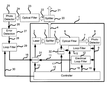
Figure 4 is a system as per figure 3 wherein a capability to lock the laser
frequency to a frequency reference element is added, according to another
preferred embodiment of the present invention.
Figure 5 is an example of an electronic board that allows the realization of
the whole system illustrated in figure 4, according to another preferred
embodiment of the present invention.
While the invention will be described in conjunction with examples of
preferred embodiment, it will be understood that it is not intended to limit
the scope
of the invention to such embodiment.
BRIEF DESCRIPTION OF PREFERRED EMBODIMENTS
Referring to figure 1, there is shown a laser system known in the art. The
optical output signal from a laser (2), preferably a semiconductor laser, is
split in
two parts by a splitter (3), one part goes as the useful output (4) and the
other part
(5) is sent to an optical filter (6). This filter is tuned by the filter
tuning signal (14) to
establish a setting point such that the filter acts as an optical phase (or
frequency)
noise to intensity noise converter. The output (7) of the filter (6) is sent
on a
photodetector (8) that converts the optical intensity into an electrical
signal (9).
This electrical signal is altered by an electrical loop filter (10) in order
to generate a
command signal (11) that is used to reduce the phase (frequency) noise of the
laser.
Referring now to figure 2, there is shown a system as illustrated in figure 1
and wherein a controller (12) is added, according to a preferred embodiment of
the
present invention. The controller receives a sample of the electrical signal
CA 02491700 2004-12-24
7
generated by the photodetector (9) and commands the frequency of the laser via
an electrical signal (13). The controller is used to implement a procedure for
the
start up and the operation of the system in order to properly activate the
laser
phase (or frequency) noise cancellation loop.
The optical filter can be a Mach-Zehnder or a Michelson Interferometer. An
error signal is generated from the interference pattern and a zero is obtained
when
the two arms are in quadrature (shifted by t90° modulo 2~). An optical
resonator
such as a Fabry-Perot or a ring could also be used in a similar fashion.
Preferably an all-fiber Michelson interferometer with Faraday mirrors is used
to avoid polarization issues. The use of polarization maintaining fiber can
also
replace Faraday mirrors. Also preferably, the tuning of the interferometer can
be
dove solely using heating elements on the interferometer fibers.
Aletrnatively, PZT
elements, or both PZT and heating elements, could be used.
In a preferred embodiment, a thermistor can be installed in the
interferometer in order to measure the internal temperature of the fiber. In a
preferred operating mode, the temperature is used as an error signal to
stabilize
the interferometer to a pre-set temperature, and then the error signal is
taken from
the interferometer output instead of the thermistor output to maintain the
optical
filter set point at the quadrature point. This procedure using a initial pre-
set
temperature allow the interferometer to operate over wider external
temperature
changes.
The optical filter can also be an optical filter band pass or band edge, for
which the laser frequency is on the edge of the transmission curve (frequency
response). Such devices could be based on Bragg gratings, on monolayer or
multilayer thin film filters, on atomic or molecular absorption lines and like
devices.
A second photodetector can be used to sense the optical output power impinging
on the optical filter and the ratio between the currents generated by the
CA 02491700 2004-12-24
8
photodetector at the output of the filter and the one at the front will allow
a
measurement independent from the laser intensity changes.
The controller can be realized using simple discrete state machines
controlling analog electronics circuitry with preset levels, or could be
implemented
using an microprocessor with embedded software.
Figure 3 illustrates another preferred embodiment of the present invention.
This system is similar to the one shown in figure 2 but a second control loop
filter
(15) is advantageously added such to allow the setting point of the optical
filter to
track the nominal frequency of the laser.
In the preferred embodiment realized with the system illustrated in figure 3,
the correction signal from the loop filter and a control signal from the
controller can
be combined by a combiner (32) before being used as a tuning signal for the
optical filter. This combiner allows the controller to adjust the setting
point of the
optical filter (17) before enabling loop filter (15) with the enable signal
(18) to
enable the locking loop.
In the preferred embodiment shown in figure 3, the controller can, via an
electrical signal (18), modify the parameters of the loop filter to adapt the
tuning
behavior of the filter and/or via the signal (19) modify the parameters of the
electrical loop filter to adapt the tuning of the laser to the dynamic of the
operation
of the system.
In a preferred embodiment, the phase noise reduction loop loop filter (10)
has a high-pass frequency response so that only high frequency fluctuations of
the
laser are compensated. No correction of the laser frequency is done at low
frequencies. Instead, the optical filter tracks the low frequency variations
of the
laser. This allows the direct frequency tuning of the laser by the input
signal (16)
which advantageously allows an external tuning capability of the laser
frequency.
This input signal (16) is combined to the feedback signal (11) and controller
(13)
CA 02491700 2004-12-24
9
with combiner (31 ) in order to generate a combined tuning signal for the
laser. The
controller can set the appropriate voltage and select the signal source in the
correct sequence to enable the locking loops at the desired operating points.
A control signal (not shown) can also be added to the input of the loop filter
(10) in order to allow fast tuning of the laser by changing rapidly the
locking point o
the laser on the optical filter.
Referring now to figure 4, there is shown another preferred embodiment of
the present invention. In this embodiment, the output signal from the laser
(4) is
sent to a splitter (20) wherein one part (21 ) becomes the useful output and
the
other part (22) is directed toward an optical filter (23). A preferred
realization of this
filter can be a resonance line from an atomic or a molecular specie but it can
also
be a specially designed optical component filter. The intensity of the
transmitted
light (24) or the reflected light (not shown on the figure) is converted to an
electrical signal by a photodetector or photomixer (25). This electrical
signal (26) is
sent to an error detection unit (27) that generates an electrical signal
bearing the
information about the frequency offset between the laser frequency and the
optical
filter (23) setting point. The electrical signal (28) generated by the error
detection is
filtered by a loop filter (29) and its electrical output signal (16) is sent
to a combiner
(31 ) to modify the laser frequency.
Although preferred embodiments of the present invention have been
described in detail herein and illustrated in the accompanying drawings, it is
to be
understood that the invention is not limited to these precise embodiments and
that
various changes and modifications may be effected therein without departing
from
the scope or spirit of the present invention