Note: Descriptions are shown in the official language in which they were submitted.
CA 02491808 2005-O1-07
HANDSAW WITH BLADE STORAGE AND AUXILIARY BLADE
BACKGROUND OF THE INVENTION
[0001] The present invention is directed generally to a handsaw formed from a
frame
and a removable main saw blade, where the main saw blade may be stored in the
frame
and the frame may support an auxiliary saw blade extending forward from the
frame.
[0002] Numerous handsaw frames have been proposed and used through time. One
typical saw frame structure is commonly referred to as a hacksaw frame.
Hacksaw
frames are generally U-shaped, with the relevant hacksaw blade operatively
supported
between forward and back downwardly extending frame portions. Examples of
hacksaws of this general design can be found in U.S. Patent Nos. 2,658,541;
2,767,751;
and 3,636,997; and more recently in U.S. Patent Nos. 5,471,752 and 6,230,412.
While
such hacksaws have been found useful in a variety of situations, there remains
a need
for alternative handsaw designs.
SUMMARY OF THE INVENTION
(0003] The present invention is directed to a saw and/or saw frame comprising:
an
elongate substantially rigid back member, a handle portion, and a swing arm
pivotally
connected to the back member distal from the handle portion so as to be
rotatable
between an extended position generally transverse to the back member and a
storage
position generally parallel and aligned with the back member; the handle
portion
comprising at least a first blade mount; the swing arm comprising at least a
second
blade mount; the back member comprising at feast a third blade mount disposed
proximate to the swing arm; each of the first, second, and third blade mounts
being
constructed to engage one end of a removably mounted saw blade of a first
type;
wherein the first, second, and third blade mounts are disposed with the swing
arm in the
Page 2 of 17
CA 02491808 2005-O1-07
extended position such that a first distance between the first and second
blade mounts
substantially equals a second distance between the first and third blade
mounts; the
back member further comprising an auxiliary blade mount mechanism adapted to
removably mount an auxiliary saw blade of a second type operatively extending
forward
from the frame; the back member further comprising a blade storage cavity
adapted to
store at feast one of the saw blades.
[0004] The auxiliary blade mount mechanism may comprise an auxiliary blade
mount, a bearing surtace disposed forward and above the auxiliary blade mount,
and an
auxiliary blade holder disposed forward and below the auxiliary blade mount.
The
auxiliary blade mount, bearing surface, and auxiliary blade holder may all be
disposed
on a side opposite the third blade mount. The saw may further comprise a quick-
release
blade tensioning mechanism operative to releasably apply a selectable amount
of
tension to the first blade mount; and wherein the frame allows conversion from
a first
configuration with a removably mounted saw blade connected between the first
and
second blade mounts and a second configuration with the saw blade connected
between the first and third blade mounts without adjustment to the selected
amount of
tension. The saw frame may further comprise a fourth blade mount; wherein the
swing
arm further comprises a fifth blade mount; wherein the fourth and fifth blade
mounts are
non-coplanar with the first, second, and third blade mounts, but are spaced a
third
distance from each other substantially equal to the first distance with the
swing arm in
the extended position. The saw frame may further comprise at least one magnet,
preferably at least two magnets spaced from each other, associated with the
blade
storage cavity. The blade mounts may comprise a tapered pin. The back member
may
further comprise an upwardly opening channel in which the swing arm is
disposed in the
storage position. The back member may further comprise a downwardly extending
lobe
proximate the swing arm, the third blade mount disposed on the lobe, and the
lobe may
Page 3 of 17
CA 02491808 2005-O1-07
comprise a bearing surface that limits the rotational movement of the swing
arm. A first
theoretical line between the first and second blade mounts may be disposed
substantially parallel to the back member and a second theoretical line
between the first
and third blade mounts may be disposed angled with respect to the back member.
The
saw may further comprise at least one saw blade. The handle portion may
comprise a
grip portion integrally formed with the back member. The handle portion may
further
comprise a quick-release blade tensioning mechanism operative to releasably
apply
tension to the first blade mount. The quick-release blade tensioning mechanism
may
comprise an operating lever pivotally mounted in an upper portion of the
handle portion.
The blade storage cavity may be elongate and accessible from above. the blade
storage cavity may be adapted to store more or more of the blades of the first
or second
types, optionally at least one of each type simultaneously.
BRIEF DESCRIPTION OF THE DRAWINGS
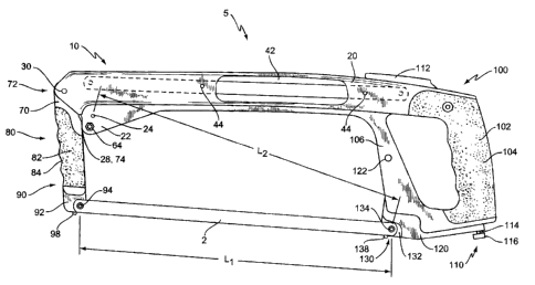
[0005] Figure 1 shows a side view of a handsaw constructed in accordance with
one
embodiment of the present invention, with the main saw blade in the horizontal
configuration (with vertical cant) and the swing arm in the extended position.
[0006] Figure 2 shows a side view of the handsaw of Figure 1 with the main saw
blade in the reduced space configuration and the swing arm in the storage
position.
[0007] Figure 3 shows a perspective view of the handsaw of Figure 1 from above
and behind, showing the blade storage cavity.
[0008] Figure 4 shows a side view from the opposite side of the handsaw of
Figure 2
with the main blade removed and the auxiliary blade operatively mounted.
[0009] Figure 5 shows a front view of the handsaw of Figure 1 with the main
blade
removed and the swing arm in the storage position.
[0010] Figure 6 shows one embodiment of an auxiliary blade.
Page 4 of 17
CA 02491808 2005-O1-07
[0011] Figure 7 shows a bottom view of the handsaw of Figure 1 with the main
blade
removed to show one possible arrangement of blade mounts.
DETAILED DESCRIPTION OF THE INVENTION
[0012] The handsaw according to the present invention allows the user to
easily
change the orientation of the longitudinal axis of a main saw blade between
two different
configurations each supported on both ends by the saw's frame, to store at
least one of
such saw blades in the frame of the handsaw, and to attach an auxiliary saw
blade to
the frame that extends forward from the frame. For clarity of discussion, and
without
limiting the scope of the attached claims, the main saw blade (which when
operatively
mounted is supported on both ends) be may be referred to as a hacksaw blade,
while
the auxiliary saw blade (which when operatively mounted is not supported on
both ends)
may be referred to as a jabsaw blade.
[0013] As illustrated in the Figures, a handsaw according to one embodiment of
the
present invention, generally designated 5, includes a frame 10 for supporting
a hacksaw
blade 2. The frame 10 includes a spine (or back member) 20 that is generally
elongate
so as to separate a handle portion 100 from a swing arm 70. While the spine 20
shown
in Figure 1 is generally rectilinear along longitudinal axis 21, the spine 20
may
alternatively be sinuous, curved, or take any other shape known in the art.
The spine 20
includes a pivot 30 and a swing arm storage cavity 32 toward its front (see
Figure 3) far
pivotally mounting and storing the swing arm 70 as discussed further below.
The spine
20 further includes a downwardly extending lobe 22 on its lower side,
proximate the
swing arm 70. The lobe 22 provides a location for a hacksaw blade mount 24 on
the
spine 20, as discussed further below. In addition, the lobe 22 may
advantageously
provide a stop face 28 as a rotational positive stop for the swing arm 70.
Page 5 of 17
CA 02491808 2005-O1-07
[0014] The swing arm 70 is pivotally mounted to the spine 20 so as to be
rotatable
between an extended position (Figure 1 ) and a storage position (Figure 2). In
the
extended position, the swing arm 70 extends downwardly with respect to the
spine 20,
while in the storage position, the swing arm 70 is generally parallel and
aligned with the
spine 20, and advantageously disposed in the swing arm storage cavity 32. The
swing
arm 70 includes an upper portion 72, a grip portion 80, and a lower portion
90. The
upper portion 72 is rotatably coupled to the spine 20 via pivot 30, which may
be of any
known type. Advantageously, the pivot 30 takes the form of a simple pin
extending
through two forwardly extending flanges on the spine 20 and a corresponding
pin
passage (not shown) through the upper portion 72 of the swing arm 70. The
upper
portion 72 may further include a stop face 74 for abutting the lobe 22 in
order to provide
a positive stop for rotation of the swing arm 70. Alternative means of
limiting the amount
of rotation of the swing arm 70 may alternatively be used. The grip portion 80
of the
swing arm 70 advantageously includes a plurality of contoured finger
indentations 84
and is advantageously covered by a suitable cushion material 82 such as a
thermoplastic elastomer. The Lower portion 90 of the swing arm 70 provides a
location
for operatively mounting the main hacksaw blade 2. The lower portion 90 may
include a
notched area forming a main blade support face 92 with a main blade mount 94
disposed thereon. The lower portion 90 may advantageously also include a
secondary
blade supporting face 96 and secondary blade mount 98 for supporting the
hacksaw
blade 2 in a 45° orientation.
[0015] The handle 100 is connected to, or integrally formed with, the rear
portion of
the spine 20. The handle 100 may include a grip area 102, hand guard 106, at
least
one blade mount 134, and a blade tensioning mechanism 110. The grip area 102
is
intended to be griped by the user's hand and may include a suitable cushion
104 if
desired. The hand guard 106 is positioned in front of the grip area 102, with
an opening
Page 6 of 17
CA 02491808 2005-O1-07
therebetween, and advantageously provides protection for the user's hand and
additional rigidity for the frame 10. The blade tensioning mechanism 110
includes a
lever 112, a pivot body 120, and a connecting rod 114 running therebetween.
The lever
112 is pivotally mounted at the upper portion of the handle 100 for movement
between a
closed/tension position generally parallel to the longitudinal axis 21 and an
open/reieased position extending upward from the handle 100. The rear portion
of the
lever 112 couples to the connecting rod 114, which runs interiorly of the grip
area 102 to
the lower portion of the handle 100. The connecting rod 114 operatively
connects the
lever 112 to the pivot body 120 (see Figure 4). The pivot body 120 is
pivotally mounted
to the middle area of the hand guard 106 and extends from that pivot point 122
down
along the hand guard 106 (mostly interiorly) and back toward the grip 102. The
lower
forward portion of the pivot body 120 includes a blade mounting area 130 that
includes a
main blade support face 132 with a main blade mount 134 thereon, and
optionally a
secondary blade support face 136 and secondary blade mount 138. The rear
portion of
the pivot body 120 includes a hole through which the connecting rod 114
extends to
engage a tension adjusting knob 116. By changing the setting of the tension
adjusting
knob 116, the "locked" position of the main blade mount 134 (and the optional
secondary blade mount 138) may be adjusted, thereby adjusting the tension
setting for
the hacksaw blade 2. This blade tension mechanism 110 is advantageously of the
"over-center locking" type.
[0016] With the swing arm 70 down in the extended position, the distance L~
between
blade mount 134 and blade mount 94 on the swing arm 70 is substantially equal
to
distance L2 between blade mount 134 and blade mount 24 on the lobe 22 of the
spine
20. This arrangement allows the hacksaw blade 2 to be easily changed from a
normal
horizontal mounting basically parallel to the spine 20 (Figure 1 ) to a
reduced space
mounting where the mounted hacksaw blade 2 is angled at angle a relative to
the spine
Page 7 of 17
CA 02491808 2005-O1-07
20 (Figure 2) so as to reduce the front profile of the saw 5, all without
requiring an
adjustment to the tension setting of the blade tension mechanism 110 via knob
116. To
achieve this, the user simply pulls up on the lever 112, which releases
tension on the
blade 2, decouples the forward end of the blade 2 from blade mount 94, rotates
the
swing arm 70 to its storage position in swing arm storage cavity 32, couples
the forward
end of the blade 2 to blade mount 24 on the lobe 22 of the spine 20, and
returns the
lever 112 to the locked position. A reverse process can also be used to change
from
the reduced space mounting to the normal horizontal mounting when desired.
This type
of two-position frame 10 conversion is generally described in U.S. Patent No.
6,606,795,
the disclosure of which is incorporated herein by reference.
[0017] It is intended that blade mounts 24,94,134 will be disposed so as to
all lie in
one plane that advantageously includes the longitudinal axis 21 of the spine
20; these
blade mounts 24,94,134 are intended for a "vertical" mounting of a hacksaw
blade 2.
Likewise, the secondary blade mounts 98,138 are intended to all lie in another
plane
that is angled 45° with respect thereto; these blade mounts 98,138 are
intended for a
"45°" mounting of a hacksaw blade 2. Further, while not required for
all embodiments,
the distance between blade mounts 98,138 may advantageously also be
substantially
equal to L~ with the swing arm 70 in the down position. Note that due to the
presence of
the auxiliary blade mounting mechanism 50, discussed below, there may or may
not be
a blade mount on the spine 20 corresponding to the 45° blade mounting
orientation,
meaning that there may or may not be the ability to quickly change from the
horizontal
blade orientation to the angled orientation (i.e., front end of blade mounted
to spine 20,
not swing arm 70) with the blade at a 45° cant in both orientations.
[0018] The spine 20 further includes a blade storage cavity 40 for storing
extra
hacksaw blades 2 or jabsaw blades 6. The blade storage cavity 40 typically
takes the
form of a relatively deep slot formed in the upper surface of the spine 20,
that may or
Page 8 of 17
CA 02491808 2005-O1-07
may not be connected to the swing arm storage cavity 32. One or more magnets
44
may be mounted in the spine 20 so as to face the blade storage cavity 40;
advantageously, there are two or more such magnets 44 at locations spaced from
one
another. In addition, an access aperture 42 on the side of the spine 20 may
connect to
the blade storage cavity 40; this access aperture 42 allows the user to
visually see if a
blade 2 is in the blade storage cavity 40 and to contact the blade 2 to urge
the same out
of the blade storage cavity 40. It is believed advantageous if the blade
storage cavity 40
has a relatively narrow cross section proximate the access aperture 42 so as
to provide
a resistance surface when the user is urging the blade 2 out of the blade
storage cavity
40 with a finger. The rear portion of the blade storage cavity 40 may be
enlarged if
desired to aesthetically balance the swing arm cavity 32 and to provide
additional
access to any saw blades 2 stored in the blade storage cavity 40. It should be
noted
that having an open top blade storage cavity 40 as shown in Figure 3 allows
for one or
more blades 2,6 to be stored in the blade storage cavity 40 and to be added
and/or
removed from above. While not required for all embodiments, the blade storage
cavity
may advantageously be sized to allow the simultaneous storage of at least one
hacksaw
blade 2 and at least one jabsaw blade 6.
(0019 The spine 20 further includes an auxiliary blade mounting mechanism 50
for
supporting an auxiliary blade 6 that forwardiy extends from the frame 10. This
auxiliary
blade 6 may be used as a "jab saw" blade, and is therefore sometimes referred
to herein
as a jabsaw blade 6, as indicated above. The auxiliary blade mounting
mechanism 50
may include an auxiliary blade mount 68, an auxiliary blade holder 60, and a
bearing
surface 54. The auxiliary blade mount 68 may be disposed on the lobe 22 in a
position
spaced reanrvardly from the frontmost portion of the spine 20. The blade
holder 60 may
be disposed forward of, and lower than, the auxiliary blade mount 68. In some
embodiments, the blade holder 68 may take the form of a simple screw
arrangement
Page 9 of 17
CA 02491808 2005-O1-07
that helps hold the auxiliary blade 6 against the side of the lobe 22. The
screw 62 may
pass through a corresponding hole (not shown) in the lobe 22 to engage a nut
64. This
nut 64 may be fitted in a corresponding recess 26 in the lobe 22 and may
advantageously be secured to the lobe 22; alternatively, the hole in the lobe
22 may be
threaded. If desired, a washer or pressing plate 66 may also be used to aid in
pressing
the auxiliary blade 6 against the lobe 22. Other forms of blade holders 60,
such as
spring clips, quarter-turn fasteners, magnets, or the like may alternatively
be used with
the understanding that a primary purpose of the blade holder 60 is to aid in
keeping the
auxiliary blade 6 engaged with the auxiliary blade mount 68 during use. The
bearing
surface 54 is disposed forward and upward of the auxiliary blade mount 68. The
bearing surface 54 may advantageously be formed as the upper wall of a
downwardly
open longitudinally extending slot 52 on spine 20. When operatively mounted,
the
auxiliary blade 6 juts forward from the frame 10 and is supported from above
by the
bearing surface 54 and from below by the blade holder 60. The auxiliary blade
mount
68 keeps the auxiliary blade 6 from moving longitudinally with respect to the
frame 10
during use. It should be noted that the various portions of the auxiliary
blade mounting
mechanism 50 may advantageously be on the side of the spine 20 opposite that
of the
hacksaw blade mount 24 on the lobe 22 to avoid interfering with the main
hacksaw
blade mounting functions.
(0020] The jabsaw blade 6 may take the form shown in Figure 6. Because this
jabsaw blade 6 is expected to be subjected to significant loads and is
supported in a
cantilever fashion, the jabsaw blade 6 is typically much thicker and shorter
than a
conventional hacksaw blade 2. With this in mind, the blade storage cavity 40
may
advantageously be sized to accommodate the jabsaw blade 6 when not mounted to
the
frame 10 via the auxiliary blade mounting mechanism 50.
Page 10 of 17
CA 02491808 2005-O1-07
[0021] While the disclosure above has been in terms of one embodiment of a
lever-
actuated blade tensioning mechanism 110, this particular mechanism is not
required in
all embodiments. Indeed, any one of a variety of blade tensioning mechanisms
may be
used, such as one operating according to any of the principles described in
U.S. Patent
Nos, 1,187,460; 1,517,827; 3,636,997; 3,822,731; 4,349,059; 4,367,779;
4,466,471;
5,673,488; or 6,134,791. Additionally, the disclosures of U.S. Patent
Applications Nos.
29/203,985 (filed 22 April 2004) and 29/204,512 (filed 29 Aprii 2004) are
incorporated
herein by reference.
(0022] The various blade mounts 24,94,134,98,138,68 discussed herein may
advantageously take the form of a short slightly tapered, but otherwise
cylindrical, pin
that is press fitted into the corresponding location. Alternatively, the blade
mounts
24,94,134,98,138,68 may be integrally formed with the corresponding components
or
take other forms known in the art.
[0023] The majority of various parts of the frame 10 may be formed of
aluminum,
steel, various plastics, or other suitable rigid materials. As mentioned
above, some or
all of the grip surfaces 82,102 may optionally be coated with a suitable
cushioning
material known in the art.
(0024] The present invention may, of course, be carried out in other specific
ways
than those herein set forth without departing from the essential
characteristics of the
invention. The present embodiments are, therefore, to be considered in all
respects as
illustrative and not restrictive, and all changes coming within the meaning
and
equivalency range of the appended claims are intended to be embraced therein.
Page 11 of 17