Note: Descriptions are shown in the official language in which they were submitted.
CA 02491838 2005-O1-06
WO 2004/016005 PCT/IB2003/003776
-1-
Telecommuaicatioa network aad upgrading method therefore
The present invention relates to a telecommunication
network comprising a plurality of nodes and bi-directional
data lines extending between two nodes in the form of
groups of at least two lines, and a method for upgrading
such a network.
Network structures of this type, in which said groups, as
a rule, are formed of precisely two bi-directional lines,
are used for fail-safe data communication, wherein two
specimens, referred to in the following as working
specimen and redundant specimen, respectively, of an
information unit inserted into the network at a given
starting node are transmitted to a target node via
different lines. Under undisturbed operation of the
network, the target node receives both the working
specimen and the redundant specimen, but takes account of
the working specimen only for forwarding to a terminal
connected to it; the redundant specimen is discarded. Only
if in case of a failure the target node does not receive
the working specimen, it will forward the redundant
specimen to the receiver terminal. In this way, a
practically interruption-free transmission operation is
guaranteed even in the case of failures of individual data
lines.
Generally, nodes of such a telecommunication network
comprise a plurality of interface circuits installed on a
plurality of circuit boards, a switching matrix and a
control unit. A function of the interface circuits is to
receive a data stream from an associated bi-directional
data line and to decompose it into a plurality of
channels, which, under the control of the control unit,
are forwarded to different interface circuits by the
switching matrix, wherein these latter interface circuits
CA 02491838 2005-O1-06
WO 2004/016005 PCT/IB2003/003776
-2-
combine a plurality of channels supplied from the
switching matrix to a data stream to be output on an
associated bi-directional data line. Interface circuits
and switching matrices are available with various
capacities, i.e. with various numbers of channels that
can be processed simultaneously. In a telecommunication
network according to the SDH standard, there are
interface circuits for 4, 16, and in the future also 64
channels, referred to as containers in the SDH-system,
and corresponding switching matrices.
The ever-increasing demand for transmission capacity in
the telecommunication networks requires a continuous
upgrade of these networks. Such an upgrade must not lead
to an interruption of the data traffic, and also the
redundancy of the data traffic should be maintained as
far as possible during an upgrade operation.
The object of the present invention is to provide a
2~ telecommunication network, components for a
telecommunication network and a method for upgrading a
telecommunication network that allow an easy and fail-
safe upgrading procedure.
The object is achieved on the one hand by a section of a
telecommunication network comprising two nodes and a
group of at least two bi-directional data lines extending
between the two nodes, wherein
- at least one of the data lines is redundant,
- each node comprises a control unit, at least one
switching matrix and a plurality of interface
circuits,
- each data line is connected to an interface circuit
of each of the two nodes,
- each interface circuit is adapted to transmit a
CA 02491838 2005-O1-06
WO 2004/016005 PCT/IB2003/003776
-3-
determined number of channels between the data line
and the switching matrix,
- the control unit of a node has access to a
configuration record which at any time indicates
existing connections between channels of the
interface circuits via the switching matrix, and
- the control unit is adapted to monitor whether an
external condition holds or not, and, if the
condition does not hold, to allow changes to
connections specified in the configuration record
and, if the condition holds, to block changes to the
connections specified in the configuration record,
but to allow further transmission of information via
the switching units of the node.
It must be understood that redundancy does not mean here
that at any time there must be a line on which no working
data are transmitted. It is sufficient if at any time the
possibility exists of distributing the existing working
data traff is among the lines so that one line becomes
free of working data traffic.
By voluntarily fulfilling the external condition, it is
possible to induce the control unit to freeze the
connections specified in the configuration record. In this
"frozen" state it is possible to remove an interface
circuit, via which the frozen connections go, to insert a
new, more powerful circuit in its place, while the
connections specified in the configuration record for
this interface circuit remain valid, and afterwards, by
unfulfilling the external condition, to allow the
specified connections to be updated according to demand.
The data lines between the two nodes may have 1+1
protection or 1:N protection. In the first case, a first
one of the two nodes transmits a working specimen and a
CA 02491838 2005-O1-06
WO 2004/016005 PCT/IB2003/003776
-4-
redundant specimen of each information unit to be
transmitted to the second node on different lines of the
group, so that as a rule the second node will only take
'account of one of the two received specimens. In case of
a failure of reception of the working specimen, it is
thus possible to recur immediately and without
interruption to the redundant specimen. In the latter
case, one of N+1 lines (N=1, 2, 3, ...) is a backup line
which, in case of failure of one of the N lines
transmitting working data, is available as a replacement
for this line. In this embodiment, the transition to the
backup line may be slightly slower than with 1+1
protection, sincelin case of a failure, the receiver must
first request the sending node to switch over to the
backup line; an advantage, however, is the more efficient
use of the lines when compared to 1+1 protection, on the
one hand due to the possibility of making safe a large
number N of lines by one backup line, on the other hand
because under undisturbed operation the backup line is
available for transmitting data traffic of low priority.
Preferably, the external condition is selected such that
it can be fulfilled or not fulfilled for each individual
interface circuit of a node independently from its other
interface circuits, and the control unit is adapted to
freeze, in case that the condition is fulfilled for one
of the interface circuits, only those connections in the
configuration record which go via the interface circuit
for which the condition is fulfilled. This is
particularly useful in a node having a plurality of
interface circuits each connected to a different other
node, because thus the freezing only affects connections
of an interface circuit which is actually to be
exchanged, while the operation of the remaining interface
circuits remains unchanged. The impediment associated
with the freezing is thus restricted to an individual
CA 02491838 2005-O1-06
WO 2004/016005 PCT/IB2003/003776
-5-
data line between two nodes; the data communication of
these two nodes with third nodes remains unimpaired.
Preferably, the configuration record further specifies
for each interface circuit of the node the number of
channels supported by it.
Preferably, the external condition is a discrepancy
between the number of channels an interface circuit is
able to process indicated in the configuration record and
the actual number of these channels. It thus becomes
possible to fulfil the external condition for freezing
the connections simply by entering the channel number of
a new interface circuit into the configuration record
before an old interface circuit is physically replaced by
this new one. Then, as soon as the new interface circuit
is inserted, the external condition is automatically no
longer fulfilled, and a specific step for unfulfilling
the condition becomes unnecessary.
Preferably, the node is adapted, after detecting
fulfillment of the condition, i.e. specifically after
changing the channel number recorded in the configuration
record, to verify only after receipt of an external
command whether the condition is still fulfilled, and to
remove the blocking in case of the condition not being
fulfilled. In such an embodiment, the frozen connections
will not automatically be "thawed" after exchange of the
interface circuit, but a corresponding command from the
user is waited for, so that before normal operation is
resumed, the user has time available for, eventually,
carrying out further measures or checks. Since not simply
a command for "re-thawing" the connections is given but a
command to check the condition, eventual errors are
recognized that may have occurred during exchange of the
interface circuit, and in case of such an error, the
CA 02491838 2005-O1-06
WO 2004/016005 PCT/IB2003/003776
-6-
connections remain frozen.
A method for upgrading the telecommunication network
section mentioned above preferably comprises the
following steps:
a) determining a data line of the group to be the line
not used for working data transmission, be it as a
carrier of redundant specimens of information units
to be transmitted in case of 1+1 protection or as a
backup line in case of 1:N protection (N=1, 2, 3,
... ) ;
b) fulfilling the external condition;
c) ~ replacing the interface circuits connected to the
selected line.
These steps are repeated until all interface circuits
connected to data lines of the group are exchanged. Then
the external condition is unfulfilled, wherein this
unfulfillment, as mentioned above already, may be an
automatic consequence of the exchange in that a
discrepancy which was voluntarily created before between
a channel number of the interface circuit to be exchanged
specified in the configuration record and its actual
channel number is removed by exchanging this circuit.
By first determining a data line of the group as a
carrier of redundant specimens and subsequently carrying
out the exchange of interface circuits at this data line,
it is ascertained that the interruption of data traffic
which is unavoidable in such an exchange does not concern
working data but only redundant data which, under normal
operation of the telecommunication network, would not
have been taken account of at their target node anyway.
CA 02491838 2005-O1-06
WO 2004/016005 PCT/IB2003/003776
_7_
I.e. during the exchange of an interface circuit there is
no interruption of the data traffic but merely a
temporarily disruption of its redundancy.
Before exchanging an interface circuit it may be
necessary to replace the switching matrix of the
concerned node by a more powerful one. In a node with at
least two switching matrices, an interruption of the data
traffic is avoided in this case by determining the
switching matrix to be exchanged as the switching matrix
for the redundant specimens of the information units to
be transmitted before exchanging it.
The method described above is straightforwardly
applicable in a telecommunication network in which. in the
group of, bi-directional data lines connecting two nodes
with each other, both the working specimens and the
redundant specimens of information units to be
transmitted between these nodes are transferred.
Incidentally, a network structure which is preferred over
networks of this type is one in which a plurality of
nodes are connected into a ring by groups of bi-
directional data lines, since these allow to transmit
working specimen and redundant specimen of an information
unit to be transmitted from the starting node to the
target node on the ring in different circulation
directions, so that the interruption of an entire group
of data lines between two nodes or a failure of a node
between start and target nodes does not prevent the
information unit from reaching the target node - as the
working specimen or the redundant specimen. In order to
make the upgrading procedure of the invention applicable
in these latter network structures, too, it is preferred
to switch over, before carrying out the above steps a) to
c), from the operating node in which working specimens
and redundant specimens of the information to be
CA 02491838 2005-O1-06
WO 2004/016005 PCT/IB2003/003776
_g_
transmitted are transferred in different directions on
the ring into a mode in which the working specimens and
redundant specimens circulate in the same direction, then
to carry out steps a) to c) and, after having exchanged
the interface modules, to revert to the initial mode with
opposite circulation directions.
Further features and embodiments of the invention become
apparent from the subsequent description of embodiments
relating to the appended Figures.
Fig. 1 is a schematic diagram of a section of a
telecommunication network in which the invention
is applicable;
Fig. 2 is a detailed block diagram of a node of _the
network section of Fig. l,in an initial stage of
the upgrading procedure;
Fig. 3 is the node of Fig. 1 after upgrading the
switching matrix;
Fig. 4 is the node of Fig. 3 after removing an
interface circuit;
Fig. 5 is the node after replacing the removed
interface circuit by a more powerful circuit;
Fig. 6 schematically represents the course of the
upgrade steps and the accompanying modifications
carried out in the configuration record;
Fig. 7 represents a portion of a telecommunication
network having nodes connected in a ring
structure; and
CA 02491838 2005-O1-06
WO 2004/016005 PCT/IB2003/003776
_g_
Fig. 8 is a configuration of the ring structure that
allows for the upgrading method of the invention
to be carried out.
Fig. 1 is a highly schematic representation of a part of
a telecommunication network having two nodes 1, 2, which
are connected directly, i.e. without further intermediate
nodes, by a group of two bi-directional data lines 3, 4.
Further ports 5 connect the nodes 1, 2 with other nodes
or telecommunication terminals, not shown.
From each information unit that is fed to node 1 by a
transmitter terminal connected to it and which is
intended for a receiver terminal connected to node 2,
node 1 generates two specimens, referred to as working
specimen and redundant specimen, respectively, which are
transferred to node 2 by the different data lines 3,4.
Tr~hile the network operates without failure, node 2
ignores the redundant specimen and only forwards the
working specimen to the receiver terminal; if due to a
failure, e.g. an interruption of line 3, the working
specimen does not arrive, node 2 switches over internally
and forwards the redundant specimen to the receiver
terminal. In spite of the failure, the receiver terminal
thus receives a complete data stream.
Fig. 2 shows schematically the internal design of node 1.
Node 2 has the same design. Node 1 comprises two
identical switching matrices 8, 9, each of which, in the
example shown here, has 16 input and output ports. Under
the control of a control unit 10, connections between
arbitrary ones of the input and output ports may be
formed. The input and output ports of the matrices 8, 9
are connected pairwise to an input interface circuit 6-1,
6-2, ..., 6-4 and to an output interface circuit 7-1, 7-2,
..., 7-4, respectively. The input interface circuits 6-1,
CA 02491838 2005-O1-06
WO 2004/016005 PCT/IB2003/003776
-10-
6-2 receive data from the other node 2 via the data lines
3, 4; the output interface circuits 7-1 , 7-2 transmit
data to the node 2 via the lines 3, 4. Other input and
output interface circuits 6-3, 6-4 and 7-3, 7-4,
respectively, are connected to other nodes of the network
via the lines 5 or to data sources and sinks,
respectively, that are locally attached to node 1.
Under normal operating conditions, node 1 receives a
working specimen and a redundant specimen of each
information unit sent to it by node 2 aria the input
interface circuits 6-1, 6-2. Both reach an input port of
switching matrix 8 and switching matrix 9, respectively.
A control unit 10 controls the two mat rices 8, 9 such
that only for the working specimen a connection to two
output ports of the matrices 8 and 9 i s switched; the
redundant specimen remains unconnected. Only in case of
non-reception of the working specimen the control unit
changes the connections in the matrices s 8, 9 such that
the redundant specimen is connected to the same output
ports as was the working specimen. To the two output
ports, output interface circuits are attached, whose
lines 5 lead to a same further node of= the network or to
a same data sink.
Mutually corresponding output ports of the two matrices
8, 9 are connected to a same output interface circuit 7-
1, ..., 7-4. When both matrices 8, 9 operate correctly,
identical information units from both matrices arrive at
the output interface circuits 7-1, 7-2. These have a
selecting switch which admits information units from only
one of the two matrices 8, 9 to line 3 and 4,
respectively, and which, in case of a failure of this
matrix, switches over to the other matrix 9 or 8,
respectively.
CA 02491838 2005-O1-06
WO 2004/016005 PCT/IB2003/003776
-11-
Each interface circuit 6-1, ..., 7-4 processes a pre-
determined number of channels. In the representation of
Fig. 2, there are four channels, symbolized by four lines
attaching each of the interface circuits to the matrix 8
and to the matrix 9. It is obvious, however, that any
other (even) number of channels would be possible.
The number of input and output ports of the: switching
matrices 8, 9 corresponds here to the total number of
channels of the interface circuits 6-1 to 7-4. If an
interface circuit was replaced by a more powerful one, it
would not straightforwardly be possible to use it, since
there are no free input/output ports of tha switching
matrices 8, 9 available that might correspond to the
increased number of channels which the interface circuit
is able to process.
A first step of a method for increasing the capacity of
the node 1 without interrupting its operati on therefore
consists of exchanging the switching matrices 8, 9. To
this end, at first a central unit (not represented) .which
may be located outside of node 1 sends an 3.nstruction to
the control unit 10 to connect the selecting switches of
all output interface circuits 7-1, ..., 7-4 to matrix 9.
When this switchover is carried out, by a subsequent
removal of matrix 8 only the redundancy in side the node
is lost, but there is no interruption of the working data
traffic.
After replacing the switching matrix 8 by a new matrix 8'
having a larger number of input/output ports, by a new
instruction to the control unit 10 the seL ecting switches
of all output interface circuits 7-1, ..., 7 -4 are set to
matrix 8', and matrix 9 may be replaced in the same way.
CA 02491838 2005-O1-06
WO 2004/016005 PCT/IB2003/003776
-12-
Fig. 3 represents the resulting state of node 1, wherein
for the sake of clarity the matrix replacing matrix 9 is
not shown. The matrix 8' here has 64 inputloutput ports,
only a quarter of which is used by the interface circuits
6-1, ..., 7-4.
The control unit 10 is associated with a configuration
register 11 that contains various information about the
structure of the node 1 and a continuously updated
directory of the connections established in the switching
matrices. The configuration record 11 helps the control
unit 10, among others, to recognize operation failures or
erroneously set operating parameters of node 1. The
operating parameters recorded in node 1 comprise, among
others, the number of channels which each interface
circuit 6-1, ..., 7-4 is able to process. This number of
channels may be set by an instruction sent from outside
to the control unit 10; however, the control unit 10 is
also capable of reading the number of channels which an
interface circuit is able to process from this interface
circuit or of measuring it. If the control unit 10
detects a discrepancy between a channel number recorded
in the configuration record 11 and an actual channel
number of an interface circuit such as circuit 6-1, it
reacts, on the one hand by generating an error message,
and on the other, by "freezing" the concerned
connections, i.e. by blocking all modifications to
connections established in the switching matrix 8' that
go via the concerned interface circuit 6-1.
The straightforward~purpose of this measure is to prevent
new connections from being generated via an interface
circuit, which might be wrongly configured and may
therefore not be capable of correctly processing the data
to be transmitted by this connection. Connections
CA 02491838 2005-O1-06
WO 2004/016005 PCT/IB2003/003776
-13-
existing before recognition of the error remain in
existence, because, if these work correctly, it is not
desirable to interrupt them, and if they do not work
correctly, letting them subsist will at least not cause,a
decrease of transmission quality.
This mode of operation of the control unit 10 and the
interface circuits 6-1, ..., 7-4 is made use of according
to the invention for upgrading the interface circuits, by
sending, for a pair of interface circuits to be
exchanged, here the circuits 6-1, 7-1 connected to line
3, after switching over all working data traffic between
the concerned node 1 and the node 2 connected to it via
lines 3, 4, to the interface circuits 6-2, 7-2 connected
to line 4, an instruction to control unit 10 to replace
the maximum channel number of circuits 6-1, 7-1 recorded
in configuration record 11 by that of circuits 6-1', 7-1'
which are to be installed in place of circuits 6-1, 7-1.
The control unit 10 recognizes the discrepancy between
the value entered in record 11 and the actual capacity of
circuits 6-1, 7-1, generates an error message and freezes
existing connections going via line 3. The circuits 6-1,
7-1 may now be removed, as represented in Fig. 4 by a
dashed outline, without this causing a deletion of the
connections going via circuits 6-1, 7-1, as would usually
be the case if an interface circuit is removed or fails.
The removed circuits 6-1, 7-1 are replaced by circuits 6-
1', 7-1' having a higher, in Fig. 5 fourfold, capacity.
For these circuits 6-1', 7-1', the number of processable
channels recorded in configuration record 11 agrees with
the real situation, so that the condition, which had
caused the connections to be frozen, no longer holds.
If the control unit 10 automatically and regularly
compares the recorded and the actual channel number, the
CA 02491838 2005-O1-06
WO 2004/016005 PCT/IB2003/003776
-14-
non-fulfilment of the condition automatically causes the
unit 10 to allow connections in which the interface
circuits 6-1', 7-1' are involved to be changed again. But
it may also be provided that the control unit carries out
such a comparison only upon reception of a corresponding
instruction. In this case, the instant when the node
resumes normal operation after an upgrade is under
control of a user, who has such an instruction sent by a
central control unit located outside the node.
i
When the interface circuits 6-1, 7-1 connected to line 3
have been exchanged., in the next step the working data
traff is is shifted from input interface circuit 6-2 to
circuit 6-1' and from output interface circuit 7-2 to 7-
a 1', so that line 4 only carries redundant data. Then, the
maximum channel number recorded in configuration record
11 for the interface circuits 6-2 and 7-2 is increased,
so that the control unit 10 again detects a discrepancy
of records and actual channel numbers and blocks changes
0 to connections of switching matrix 0' that go via line 4.
Now the circuits 6-2, 7-2 shown in dashed lines in Fig. 5
may be exchanged as described above for circuits 6-1, 7-
1.
It is understood that the input and output interfaces
referred to above as separate units may be combined into
pairs, so that they can only be exchanged by pairs.
The same steps are carried out at node 2, so that finally
30 at both ends of lines 3, 4, there are more powerful
interface circuits that allow an operation of the lines
at a higher rate andlor with a higher multiplex.
Fig. 6 shows in form of diagrams the individual steps
35 that have to be carried out at nodes 1, 2 when exchanging
the interface circuits connected to lines 3, 4. In Fig.
CA 02491838 2005-O1-06
WO 2004/016005 PCT/IB2003/003776
-15-
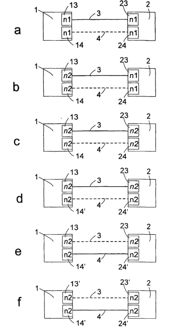
6, the nodes 1, 2 are shown as rectangles, each of the
smaller rectangles 13, 14, 23, 24 shown within
representing a bi-directional interface formed by the
input and output interface circuits connected to line 3
or 4, respectively, in node 1 or 2, respectively.
Inscriptions n1, n2 within the rectangles of circuits 13,
14, 23, 24 indicate the number of channels recorded in
the configuration record 11 as the number of channels of
the corresponding bi-directional interface. In Fig. 6a,
this number is n1 for all interfaces. Upon an instruction
from the user, the control units of 1, 2 have
concentrated the working data traffic onto the interfaces
13, 23 and the data line 3 extending between them,
whereas the redundant data traffic goes over interfaces
14, 24 and data line 4 connecting them. The
representation of the data lines 3, 4 as solid or dashed
lines indicates, in all parts of Fig. 6, the property of
the data lines 3, 4 of being carrier of working or
redundant data traffic.
Fig. 6b shows the configuration of the two nodes when
node 1 has received and carried out an instruction to
change the channel number recorded in configuration
record 11 for the interfaces 13, 14 to a new value n2.
The control circuit of node 1 recognizes an error,
symbolized by the representation of the channel number n2
in italics, so that connections via node 1 and the lines
3, 4 may neither be established nor broken off.
A corresponding change is also effected in the
configuration record of node 2, so that here, too, a
configuration error is detected, represented by the
inscription of interfaces 23, 24 in italics in Fig. 6c.
In the next step, the interfaces 14 of node 1 and 24 of
node 2 that carry no working data traffic are replaced by
CA 02491838 2005-O1-06
WO 2004/016005 PCT/IB2003/003776
-16-
a larger interface 14', 24' having the channel number n2.
When the nodes 1, 2, of their own motion or because they
have received a corresponding instruction, compare the
processing capacity of the exchanged interfaces 14', 24'
with the one recorded in configuration record 11, they
find that there is no discrepancy any more, and they
delete the error message, represented by the inscription
in interfaces 14' and 24' appearing in normal type again
in Fig. 6d. Thus, the interfaces at data line 4 are
upgraded, and in the next step, the user data traffic is
switched over to these, represented by a solid line 4 in
Fig. 6d.
Since now the interfaces 13, 23 carry no more working
data, they may also be replaced by interfaces 13', 23'
having n2 channels, so that for these too, the maximum
channel number recorded in the configuration record
agrees again with reality (Fig. 6f). The restriction of
the user data traffic to one of the two lines 3, 4 may
now be removed again, whereby the process of exchanging
the interface circuits is finished.
Since due to the freezing of connections in the switching
matrices during the discrepancy between the actual
channel number and the channel number recorded in
configuration record 11, the existing connections remain
switched in the switching matrix even if one of the
interface circuits via which they normally go is removed,
data traffic may be resumed via a new interface circuit
as soon as it has been built in. The redundancy of the
telecommunication network is thus only impaired during
the short period in which an interface circuit is
actually missing. As soon as a new interface circuit is
built in, the redundancy is completely restored.
In the above description of the embodiments, 1+1
CA 02491838 2005-O1-06
WO 2004/016005 PCT/IB2003/003776
-17-
protection of the transmission on lines 3. 4 was assumed.
In the 1:N protection mechanism one line out of N+1 lines
is determined as a backup line on which, under normal
operating conditions, void data or low priority data are
transmitted, the transmission of which may be interrupted
in case of need. When the node that receives data detects
a failure of a line transmitting working data, it informs
the sending node which then transfers transmission from
the failed line to the backup line.
Fig. 7 shows a portion of a network with a plurality of
nodes, four modes in the present case, which are
connected to form a ring structure by data lines 3, 4
extending in pairs between them. In such. a ring
structure, it is advantageous to design a 1+1 protection
mechanism so that working and redundant specimens of
information units that are fed into the network by a
terminal at a port 5 at node 1 and are intended for node
2 are transmitted there with different circulation
directions (represented as arrows in node 1) on the lines
3 and 4 of the ring, respectively, so that e.g. the
redundant specimen is transmitted on the inner ring 3 and
is discarded in node 2, whereas the working specimen
circulating on outer ring 4 is forwarded to a port 5 of
node 2.
Analogously, 1:1 or 1:N protection between nodes 1, 2 may
be implemented if in case of a failure of a section of
ring line 3, 4 sections of the same or another line that
are complementary to the failed sections are used as a
backup line.
This creates an increased degree of failure safety of the
network when compared to an operating mode in which
working and redundant specimens of an information unit
circulate in the same direction of the ring. As is easily
CA 02491838 2005-O1-06
WO 2004/016005 PCT/IB2003/003776
-18-
recognized, in a co-circulating mode in case of an
interruption of the lines 3, 4 directly connecting nodes
1, 2, no transmission between the nodes would be possible
anymore, whereas in a countercirculating mode the
redundant specimen reaches node 2 and may be forwarded to
a receiver terminal at port 5. The upgrade of a ring
network operated in this way is much more difficult than
the case considered above referring to Fig. 1, since
temporarily overlapping upgrades in a plurality of nodes
of the ring become necessary. However, simultaneous
interruptions at several places may lead to a complete
interruption of transmission, which must be avoided under
all circumstances.
However, this problem is solved by switching over the
operating mode of the ring of Fig. 7 temporarily to a co-
circulating propagation pattern for working and redundant
specimens of the information units, as indicated in Fig.
8. In such an operating mode, the ring disintegrates into
four regions of the type shown in Fig. 1, which may each
be upgraded individually without having to take
interactions with the other regions into account.