Note: Descriptions are shown in the official language in which they were submitted.
CA 02491840 2005-01-06
Attorney Docket No: PLA-117(US)
INTEGRATED CUTTING TOOL FOR WASTE DISPOSAL APPARATUS
FIELD OF INVENTION
[0001] The present invention relates generally to a waste disposal apparatus
and a method for disposing waste material. More particularly, the present
invention is
directed to an apparatus having a cutting tool integrated with a mechanism for
sealing a
tubular sealing material containing waste, and to a method of using the waste
disposal
apparatus.
BACKGROUND OF INVENTION
[0002] Conventional waste disposal devices and systems are generally
available to dispose waste ranging from kitchen refuse to soiled diapers. Most
waste
receptacles require separate and numerous actions for packing waste and
disposing
them.
[0003] European patent application No. 0005660 describes a device for
disposing kitchen refuse in packages enclosed by flexible tubing derived from
a tubular
pack of tubing surrounding a tubular guide. The device includes a tube sealing
mechanism. The tubing passes from the pack over the top of and then down the
guide
to a position beneath the guide where it has been closed by fusion to provide
a
receptacle within the guide means. When this receptacle is full of refuse, a
lever is
manually operated to actuate an electro-mechanical apparatus including
clamping and
fusion devices that travel round closed tracks to perform the four-fold task
of drawing
the receptacle down below the tubular guide, fusing the tubing walls together
to seal
the top of the receptacle, sealing the tubing walls together to provide the
closed base of
the next receptacle and dividing the tubing by heat at a location between
these two
fusion locations to separate the filled package.
EXPRESS MAIL LABEL NO: EV162126131US Page 1 of 16
110160500v1
CA 02491840 2009-02-12
76633-16
[0004] A popular approach for disposing of diapers has been a device using,
for example, a tube twisting mechanism to form a pouch about a diaper. Such a
device
is disclosed in U.S. Patent No. 4,869,049. The patent discloses an apparatus
to form
packets containing disposable diapers comprising a tubing which passes through
the top
edges of a core opening and then down through the core. The core is turned by
means
of a twist ring/drive about a cylinder to twist the flexible material at
locations between
the adjacent packets to seal the packets at their ends thereby providing
disposal of the
waste. A manually rotatable cutter in the lid is provided for severing the
flexible tubing
above the twisted packets.
[0005] A commercially available waste storage device for disposal of baby
diapers is known as the Playtex Diaper Genie . In the Diaper Genie , a waste
storage
container is fitted with a lid designed to contain odors when the lid is
closed. The lid
also has a rotatable cutting device designed to sever a storage film from a
film cassette
positioned in the waste container body. The fiim cassette having a hole
concentrically
located therein, is positioned in the waste container body. The film cassette
has a top
surface from which the storage film extends and has a removable twist drive
placed in
the concentric hole of the cassette. The storage film extends from the film
cassette, over
and then down through the twist drive, down through a hole in the film
cassette and
into the waste container body, all in the shape of a tube. The user manually
opens the
lid assembly by hand and places waste such as a diaper through the twist drive
and hole
in the fiim cassette, into the storage film tube. The twist drive is then
manually rotated
by the user's hand, which causes the film cassette and stored film to rotate,
sealing off
the disposed waste in the storage film to form a packet or a pouch with a
continuous
twisted link still attached to the storage film. The storage film is
continuously fed from
the film cassette as additional links of packets or pouches are formed. The
last link is
then severed from the storage film when the waste receptacle has been filled
to
capacity. This is accomplished by closing the lid and pressing down and
rotating a
rotatable cutting device accessible from the top of the lid, thereby severing
the film from
around the rim of the film cassette, now exposed in the absence of the twist
drive.
Page 2 of 16
CA 02491840 2009-02-12
76633-16
[0006] From the above it can be understood by those having ordinary skill in
the art that there are a number of disadvantages associated with prior art
waste
disposal devices using flexible tubing and tubular sealing material to form
packets for
disposal of waste materials. It will also be appreciated by those skilled in
the art that the
steps of placing and positioning the twist drive in the device first by
opening a lid, then
twisting the ring to seal the waste material inside the film tube, closing the
lid, then
reopening the lid, closing the lid again before cutting the fiim may be
cumbersome and
time consuming. It is clear that a device is needed that will eliminate these
disadvantages. Such a device should be relatively safe, economical to
purchase, and
easy to operate with fewer interventions by the user.
SUMMARY OF INVENTION
[0007] The present invention provides a waste disposal apparatus and a
method for disposing waste material. Specifically, the present invention is
directed to an
apparatus having a cutting tool integrated with a mechanism for twistably
sealing and
cutting a tubular sealing material containing waste, deposited in such sealing
waste in a
tubular sealing material to form a series of waste packages, and to the use
thereof. The
disclosed integrated twist-and-cut (ITAC) system provides an improvement over
existing
waste disposal systems by eliminating intervening steps of disposing waste
material.
[0008] An embodiment of the present invention comprises an integrated
cutting system for a waste storage receptacle. A container body defines a
waste bin.
An opening provides access to the waste bin. A support in the form of a collar
resides
adjacent the opening. The collar has a flange extending therefrom and is
cylindrically
configured for mounting a film cassette above the waste bin. The collar
encloses less
than all of the opening to the waste bin so that waste material can be passed
through
the opening and into the waste bin. The invention further comprises a film
cassette
mounted to the flange of the collar, and a lid hingedly adjacent the collar.
The lid
portion encloses a first device for a fllm sealing means for forming waste
packets by
Page 3 of 16
CA 02491840 2009-02-12
76633-16
twisting a flexible film tubing that is dispensed from the film cassette. The
lid portion
also encloses a second device operably connected to the first device for
cutting the
waste packet from the fiim tubing.
[0009] Another embodiment of the present invention comprises an integrated
cutting system for a waste storage receptacle. The waste storage receptacle
has a
body, a collar, a lid and a storage film cassette adapted to be positioned in
the collar.
The cassette has a continuous length of a tubular storage film therein. The
invention
further comprises a handle operably connected to the lid. The operation of the
handle
engages a cutting device and a film sealing device to uniform rotational
motion, and
twistably seals the film extending from the cassette. A button is also
operably
connected to the lid. The operation of the button disengages the sealing
device from
rotation and exposes the cutting device to the film in a stationary state.
Further
operaliori of the handle rotates a blade affixed to a blade 5hoe, lhe blade
severing the
film from the cassette.
[0010] Still another embodiment of the present invention involves a method
for disposing waste material from a waste disposal apparatus. The method
provides a
lid having a sealing device and a cutting device therein. The sealing device
is operable
by a rotatable handle, and the cutting device by a button. A length of film
tubing is
provided. The tubing has a first sealed portion of the tubing at a location
along its
length and an open end. The method involves inserting, with the lid open,
waste
material through the open end of the tubing until it contacts the first sealed
portion of
the tubing; closing the lid; rotating the handle to rotate the sealing device
and the
cutting device simultaneously to only twist and seal the open end of the
tubing;
operating the button downwards and disengaging the sealing device; operating
the
rotatable handle to rotate the cutting device only, and cut the waste packet
only; and
discarding the waste packet from the waste disposal apparatus.
Page 4 of 16
CA 02491840 2009-02-12
76633-16
According to another embodiment of the present
invention, there is provided an integrated cutting system
for a waste storage receptacle comprising: a container
defining a waste bin and an opening that provides access to
the waste bin; a support adjacent the opening, the support
in the form of a body having a flange extending therefrom
that is circumferentially configured for holding a film
cassette above the waste bin, wherein the body encloses less
than all of the opening to the waste bin so that waste
material can be passed through the opening and into the
waste bin; a film cassette on the flange; and a lid hingedly
adjacent the body; the lid portion enclosing a first device
for a film sealing for forming waste packets by twisting a
flexible film tubing that is dispensed from the film
cassette; the lid portion enclosing a second device operably
connected to the first device for cutting the waste packet
from the film tubing.
According to still another embodiment of the
present invention, there is provided an integrated cutting
system for a waste storage receptacle, the waste storage
receptacle having a receptacle body, a collar, a lid and a
storage film cassette adapted to be positioned in the
receptacle body, the cassette having a continuous length of
storage film therein, the integrated system comprising: a
handle operably connected to the lid, wherein the operation
of the handle engages a cutting device and a film sealing
device for uniform rotational motion to twistably seal the
film extending from the cassette; a button operably
connected to the lid, wherein the operation of the button
disengages the sealing device from rotation and exposes the
cutting device to the film in a stationary state; and a
blade affixed to the cutting device; wherein when the button
4a
CA 02491840 2009-02-12
76633-16
is operated the operation of the handle rotates the blade to
sever the film from the cassette.
According to yet another embodiment of the present
invention, there is provided a method for disposing waste
material from a waste disposal apparatus, comprising the
steps of: providing a lid having a sealing device and a
cutting device therein, the sealing device being operable by
a rotatable handle, and the cutting device by a button;
providing a length of tubing having a first sealed portion
of the tubing at a location along its length and an open end
of the tubing; inserting waste material, with the lid open,
through the open end of the tubing until it contacts the
first sealed portion of the tubing; closing the lid;
operating the rotatable handle and rotating the handle to
rotate the sealing device and the cutting device
simultaneously to only twist and seal the open end of the
tubing; operating a button downwards and disengaging the
sealing device; operating the rotatable handle to rotate the
cutting device only, and cut the waste packet only.
According to a further embodiment of the present
invention, there is provided a waste storage device
comprising: a container defining a waste bin and an opening
that provides access to the waste bin; a collar mounted on
the container adjacent the opening, the collar including a
body with a flange extending therefrom that is
circumferentially configured for holding a film cassette
above the waste bin, wherein the body encloses less than all
of the opening to the waste bin so that waste material can
be passed through the opening and into the waste bin, the
film cassette being positionable on the flange, the film
cassette having a rim defining an open core, wherein a
tubular film is dispensed from the rim; and a lid hingedly
mounted to the collar, a first device mounted in the lid for
4b
CA 02491840 2009-02-12
76633-16
selectively sealing the tubular film for forming a waste
packet that is dispensed from the film cassette; and a
second device mounted in the lid operably connected to the
first device for cutting the waste packet from the tubular
film.
According to yet a further embodiment of the
present invention, there is provided a waste storage device
comprising: a receptacle body; a collar; a lid; a storage
film cassette adapted to be positioned in the receptacle
body, wherein the storage film cassette has a continuous
length of storage film therein; a cutting device; a film
sealing device; a handle operably connected to the lid,
wherein operation of the handle engages the cutting device
and the film sealing device to move and seal the storage
film extending from the storage film cassette; a button
operably connected to the lid, wherein actuation of the
button disengages the sealing device from movement and
exposes the cutting device to the storage film in a
stationary state; and a blade affixed to the cutting device,
wherein the operation of the handle moves the blade with
respect to the storage film to sever the storage film from
the storage film cassette when the button is actuated.
According to still a further embodiment of the
present invention, there is provided a method for disposing
waste material from a waste disposal apparatus, comprising:
providing a lid having a sealing device and a cutting device
therein, the sealing device being operable by a movable
handle, and the cutting device being operable by a button;
providing a length of tubing having a first sealed portion
of the tubing at a location along a length thereof and an
open end of the tubing; inserting waste material, with the
lid open, through the open end of the tubing until it
contacts the first sealed portion of the tubing; closing the
4c
CA 02491840 2009-02-12
76633-16
lid; operating the movable handle to move the sealing device
and the cutting device simultaneously to only move and seal
the open end of the tubing to form a waste packet; actuating
the button to disengage the sealing device; and operating
the handle to move the cutting device only to cut the waste
packet only.
According to another embodiment of the present
invention, there is provided a waste storage device
comprising: a container defining a waste bin and an opening
that provides access to the waste bin; a collar mounted on
the contairier adjacent the opening, the collar including a
body with a flange extending therefrom that is
circumferentially configured for holding a film cassette
above the waste bin, the film cassette having a rim defining
an open core, wherein a tubular film is dispensed from the
rim; and a lid hingedly mounted to the collar, a first
device mounted in the lid for selectively sealing the
tubular film for forming a waste packet that is dispensed
from the film cassette; and a second device mounted in the
lid operably connected to the first device for cutting the
waste packet from the tubular film.
4d
CA 02491840 2005-01-06
Attorney Docket No: PLA-117(US)
BRIEF DESCRIPTION OF DRAWINGS
[0011] Figure 1 is a perspective drawing of the waste disposal apparatus of
the present invention showing the primary parts, including the body, collar,
rotatable
handle, and cutting button of the apparatus.
[0012] Figure 2a is an exploded view showing the components of an
embodiment of an integrated twist-and-cut (ITAC) system, according to the
present
invention.
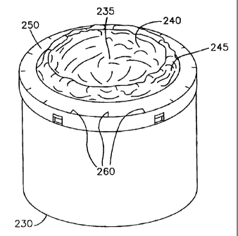
[0013] Figure 2b is a schematic drawing of a tubing refill cassette, according
to US Application No: 60/499,443.
[0014] Figure 3a is a partial cut-away of the apparatus of Figure 1, showing
the forniing of waste packets by twisting and sealing of a flexible material,
according to
the present invention.
[0015] Figure 3b is a cross-sectional view of the apparatus of Figure 1,
showing the placement of a film cassette in relation to a rotary twist drive
and a blade
shoe, according to the present invention.
[0016] Figure 4a is a partial cross-sectional view of the apparatus of Figure
1, showing the position of the components of the ITAC system in twist mode,
only.
[0017] Figure 4b is a partial cross-sectional view of the apparatus of Figure
1, showing the position of the components of the ITAC system in cut mode,
only.
DETAILED DESCRIPTION
[0018] Referring now to Figures 1, 2, 3a-3b and 4a-4b, there is shown one
waste disposal apparatus embodiment of the present invention utilizing an
integrated
twist-and-cut system for packing and disposing of waste materials.
EXPRESS MAIL LABEL NO: EV162126131US Page 5 of 16
110160500v1
CA 02491840 2005-01-06
Attorney Docket No: PLA-117(US)
[0019] In Figure 1, reference numeral 10 generally represents a waste
storage and disposal apparatus having a body 100, a collar 200 and a lid 300.
Body
100 seives as a receptacle for temporarily storing waste materials introduced
into
apparatus 10 through lid 300 and sealed in packets in the collar section 200,
as will be
explained more in detail with reference to Figures 2 and 3 below. Body 100 as
shown is
substantially cylindrical in shape. However, alternative shapes for body 100
can also be
used including rectangular or cubical. Body 100 has a hinged base 105 and a
latch
115 to lock and release the bottom base of the receptacle to provide access to
stored
waste products inside the receptacle. As would be understood by one of
ordinary skill in
the art, the hinged base 105 can be located at any other surface of body 100,
such as
the side.
[0020] Collar 200 is substantially cylindrical in shape and has a diameter
substantially the same size as at least one the diameter of body 100 to
provide a
sealing engagement of the collar with the body along the conjoining portions.
If an
alternative shape of body 100 is used, such as rectangular or cubical, then
the
corresponding mating shape would also be used for collar 200 to provide a
sealing
engagement of the collar with the body along the conjoining portions.
[0021] Lid 300 provides the function of housing the mechanisms for the
ITAC system of the present invention. The lid and the integrated twist-and-cut
system
therein will be described more in detail in the preferred embodiments shown in
Figures
2, 3a-3b and 4a-4b below. Lid 300 as illustrated is also substantially
cylindrical in shape
and has a diameter substantially the same size as the diameter of collar 200
to provide
a sealing engagement of the lid with the top along the conjoining portions.
Lid 300 is
pivotally connected to collar 200 by a lid hinge preferably in the rear (not
shown in
Figure 1). Lid 300 has a lid slot 305 formed therein. Lid slot may comprise a
button
for ease of latching and unlatching. Lid slot 305 may be a u-shaped channel
that is
operably connected to a lid latch 205 to allow user to open and close lid 300.
Lid latch
205 is better seen in Figures 2 and 3b discussed below.
EXPRESS MAIL LABEL NO: EV162126131US Page 6 of 16
110160500v1
CA 02491840 2009-02-12
76633-16
[0022] An aspect of an embodiment of the present invention involves a
handle 310 operably interconnected to a button 320, both formed in lid 300, as
shown
in Figure 1. Handle 310 is configured to be mechanically rotatable by hand. A
spur
gear may be operationally configured to permit the rotatable handle to be
rotated in
only one direction. Rotatable handle 310 engages and rotates in unison a
rotary twist
drive 360 and a cutting tool 370. Thus, rotatable handle 310 performs not only
the
conventional function of forming continuous waste packets 227, such as shown
in Fig.
3b, from a flexible film 223, but also the function of severing the packets
from the film;
however, without having to open the lid and performing additional steps. This
is
accomplished, according to the present invention, by depressing button 320
which
automatically disengages the rotary twist drive 360 and continuing with the
rotating
action of the handle only to expose now a nonmoving, stationary flexible film
223 to a
rotating blade shoe 377, such as a blade, as shown in Figures 2 and 3b.
[0023] Aspects of an embodiment of the present invention are shown in
Figure 2a, which is an exploded view of collar 200 and lid 300 of Figure 1.
Lid 300 is
pivotally connected to collar 200 by a lid hinge at 207 preferably in the
rear, as shown
in Figure 2a. Lid 300 can easily be opened or sealably closed over collar 200
by
engaging or disengaging lid latch 205 to and from lit slot 305. Lid 300 is
configured to
house the various components of an integrated twist-and-cut, ITAC, embodiment
system, including wave spring 330, clutch plate 340, yoke 350, rotary twist
drive 360,
and blade shoe 370, as explained below in detail, so that, when opened, the
lid carries
with it all the ITAC components, and provides direct access to a flange 209 of
the collar
where a cassette of film is placed. Cassette 220 is shown in Figure 3.
[0024] Collar flange 209 is formed circumferentially about the inner circular
wall 210 of the collar as shown in Figure 2a. Circular wall 210 extends
substantially
vertically upward from flange 209. As used here, horizontal refers to the
direction
between collar latch 205 in the front and lid hinge 207 in the rear as
oriented in Figure
2a, which is substantially perpendicular to the sidewalls defining collar 200.
Vertical
refers to the direction between lid 300 and collar 200. Circular wall 210 has
a diameter
larger than the diameter of cassette 220 as shown in Figures 3a-3b and 4a-4b
(not
shown in Figure 2a). Circular wall 210 provides support for cassette 220 to
prevent it
Page 7 of 16
CA 02491840 2005-01-06
Attorney Docket No: PLA-117(US)
from moving in a horizontal direction yet allowing it to rotate about the
center of the
collar.
[0025] Referring again to Figure 3b, cassette 220 stores the flexible film
which emanates from the cassette through gap 225 and then fords flange 209
area
(hidden underneath the film). Rotatable handle 310 then engages the rotary
twist drive
360, thereby twisting the film 223 having waste material, such as a soiled
diaper,
garbage, etc. previously introduced into the film through the open lid, and
sealing the
film in a tubular form, thus sequestering the waste material in packets 227.
The same
rotatable handle is then used to sever, for example, the last packet from the
film of the
cassette when receptacle 100 is full and ready to be emptied by releasing
latch 105 in
Figure 1.
[0026] In one embodiment of the present invention shown in the exploded
view in Figure 1, rotatable handle 310 has a substantially round upper portion
311 and
a cylindrical neck 313 which extends through all the openings centrally formed
in the
components of the ITAC system, in the order starting from lid 300, wave spring
330,
clutch plate 340, yoke 350, rotary twist drive 360 and engages shoulder 373 of
blade
shoe 370. Handle 310 is, therefore, capable of imparting rotational motion
directly to
blade shoe 370 with rim 375. In one embodiment, it is preferred that the
engagement
of neck 313 to shoulder 373 is in the form of a split spline as shown in
Figure 2a,
although it will be understood by those skilled in the art that the engagement
of the
neck to the shoulder can be accomplished in different ways, including a press
fit neck
into a sleeve.
[0027] In an embodiment of an aspect of the invention, wave spring in
Figure 2a comprises an undulating shape with opening 335, and the undulating
portions
press upon the upper portion of lid 300 (not shown) when inserted about the
neck 313.
The bottom surface of the wave spring has protrusions 333 as shown in the same
Figure. It will be understood that springs of other shapes, including types of
protrusions
other than shown in Figure 2a can also be used. Protrusions 333 of the wave
spring
press against corresponding recesses (not shown) formed in a lower surface of
clutch
EXPRESS MAIL LABEL NO: EV162126131US Page 8 of 16
110160500v1
CA 02491840 2009-02-12
76633-16
plate 340 shown in Figure 2a. Clutch plate 340 has an upper surface 341 in the
form
of a ring with geared teeth 343. Teeth 343 engage rotatably with teeth located
in lid
300 (not shown) when button 320 is depressed. The clutch plate locks the
rotary twist
drive 360 in place when button 320 is pressed.
[0028] In another embodiment of an aspect of the invention, clutch plate
340 has a plurality of vertical projections 345 formed on its lower surface,
as shown in
Figure 2a. Vertical projections 345 of clutch plate 340 engage in
corresponding
openings 363 that are formed in rotary twist drive 360 shown in Figure 2a. In
operation, any rotational motion imparted by handle 310 is transmitted to the
blade
shoe 370, which is operably connected to the handle via neck 313 of the
handle. In
turn, vertical projections 345 of the clutch plate transmit the rotational
motion to the
rotary twist drive 360. It will be noted in Figure 2a that the blade shoe 370
nests
inside the dome-like cavity 365 under the rotary twist drive 360, wherein
blade 377
(there may be two or more blades although only one is shown in the diagram) is
positioned coplanarly with ribbed surface 367 of the rotary twist drive.
Figure 2a,
therefore, shows an embodiment which may be employed in an aspect of the
invention,
wherein the rotation of handle 310 provides zero, or stationary, relative
motion
between the rotary twist drive 360 and the blade shoe 370, thereby providing
only a
twisting action of the flm 223 on the rim 250 of the cassette 230 shown in
Figures 2b
and 3a to seal refuse previously deposited into the film, and form packets
227. The
cassette rim 250 contains ribs 260 (Figure 2b) that allow the twist drive
teeth to engage
it and rotate it.
[0029] A tubing rehil cassette is shown in Figure 2ab as cited in US
Application 60/499,443. A rotary grip ring or a rotary twist drive may be used
to rotate
the body of cassette 220 effectively twisting the flexible tubing 240 which
emanates
through a gap 245 between rim 250 of cassette 220 and the open cassette core
area
235, and is folded down through the open cassette core area 235 into an
interior bin
space. The bottom rim 230 of the film cassette rests on several glide buttons
that are
afFixed, for example, to the flange support which may be affixed to the
internal wall side
Page 9 of 16
CA 02491840 2009-02-12
76633-16
of a waste bin. Glide buttons alleviate friction between the bottom of the
body of cassette
220 and the surface it rests on, and allow the refill to freely rotate in the
body 100.
[0030] Another aspect of the present invention involves a yoke 350
positioned between clutch plate 340 and rotary twist drive 360. Yoke 350 is
generally
u-shaped having lateral projections 351 and a curvilinear shoulder 353, as
shown in
Figure 2a. In assembly, lateral projections 351 straddle vertical projections
345 of
clutch plate 350 and slidably press against the lower surface 347 of the
clutch plate.
The curvilinear portion of shoulder 353 protrudes beyond the periphery of the
clutch
plate 340 to accommodate the seating of a button 320 in a recess 355 on the
shoulder
of the yoke, without interference by the clutch plate. Button 320 is operably
connected
to lid 300, and is better seen in Figures 4a and 4b. In its normal position ,
that is,
when the button is not depressed as seen in Figure 4a, vertical projections
345 can
rotate freely in between lateral projections 351 when set into motion by
rotating handle
310, thus also rotating the rotary twist drive 360, as described above. Rotary
twist
drive 360 has a drive collar 361 with a plurality of openings 363
corresponding to the
plurality of clutch plate projections 345 which engage the openings to rotate
the rotary
twist drive 360. Figure 4a shows a cross-sectional view of the positions of
the
components of the ITAC system in the twist mode, only.
[0031] An embodiment of an aspect of the present invention provides a
means for lifting the clutch plate vertically and disengaging the vertical
projections 345
of the clutch from openings 363 in the rotary twist drive 360, thereby
allowing only the
blade shoe 370 to rotate when set into motion by rotating handle 310 and sever
the
flexible fi1m223 from the rim of the cassette, as shown in Figures 3a and 3b.
This
function is provided by button 320, which, when depressed, causes the shoulder
353 of
the yoke to move downward, while moving the lateral projections 351 upwards to
lift
the clutch plate 340. It will be noted that in the absence of any twisting
action, flexible
film 223 in Figures 3a and 3b remains stationary, and hence the relative
motion
between the blades 377 and film 223 will cut the film. Although it may be
preferred
that a pair of diametrically opposed blades be used along the periphery of the
circular
Page 10 of 16
CA 02491840 2005-01-06
Attorney Docket No: PLA-117(US)
blade shoe 370 of the invention, it will be understood by workers in the field
that any
plurality of various shapes of blades can also be used.
C0032] Figure 4b shows a cross-sectional view of the positions of the various
components of the ITAC systeni in the cut mode, only. Specifically, it will be
noted that
button 320 is pushed downwards into lid 200, and yoke 350 is tilted so that
vertical
projections 345 of clutch 340 are lifted out of the recesses 363 of the rotary
twist drive
360.
[0033] While the invention has been particularly shown and described with
reference to particular embodinients, those skilled in the art will understand
that various
changes in form and details may be made without departing form the spirit and
scope of
the invention. For example, the handle and button operations can be automated.
Furthermore, an indent can be provided for the button so that one need not
hold down
both the button and the handle during the cutting operation. Also, a number of
clicks
can be incorporated to the turning of the rotatable handle to signal
positively the end of
twisting of the film material in forming waste packets. In addition, a
sighting can be
provided to show the waste bin reaches the full capacity. Cutting blade shown
in Figure
2a can also be made replaceable for ease to the user as depicted by blade
cartridge 379
in the same Figure 2a.
EXPRESS MAIL LABEL NO: EV162126131US Page 11 of 16
110160500v1