Note: Descriptions are shown in the official language in which they were submitted.
CA 02491851 2010-08-02
,
,
ELECTRONIC MONITORING DEVICE FOR ATTACHING TO A TYRE
BACKGROUND OF THE INVENTION
1. TECHNICAL FIELD
The invention generally relates to mounting arrangements for electronic
monitoring devices and, more particularly, to an electronic monitoring device
and
patch assembly wherein the electronic monitoring device is removably attached
to the
patch so that the electronic monitoring device may be repeatedly removed from
and
reattached to the patch. Specifically, the present invention relates to a
patch that
removably and re-attachably holds an electronic monitoring device having a
rounded
body.
2. BACKGROUND INFORMATION
Monitoring the engineering conditions of tires is becoming more and more
desirable in the art. The monitored engineering conditions include internal
pressure
and internal temperature and other conditions that are useful for improving
tire
efficiency in the field. Monitoring tire conditions on large off-the-road
equipment
has become especially desirable given the costs of the tires.
Prior art methods of monitoring large truck tires have included passive
integrated circuits embedded in the body of the tire, or self-powered circuits
which
are positioned external to the tire. The passive integrated circuits rely on
inductive
magnetic coupling or capacitative coupling to energize the circuit, thus
providing
power to the circuit from a source remote from the tire. Self-powered circuits
positioned external to the tire are exposed to damage from the environment
such
1
CA 02491851 2010-08-02
as weather, road hazards and even vandalism.
Recent engineering advances have permitted the installation of monitoring
devices having active integrated circuits within tires. One such device is
described in
U. S. Patent No. 5,562, 787 to Koch et al. entitled Method of Monitoring
Conditions
of Vehicle Tires, and assigned to the assignee of the present invention. These
devices
include an active circuit powered by a dedicated long life, miniature battery
and at
least one sensor for detecting, optionally storing and transmitting real time
engineering conditions within the tire. Such devices
are capable of being
programmed to remain in an active, but dormant condition, but will switch
automatically to an "awakened" condition in response to an external signal or
a
condition which exceeds preset limits.
These devices have been mounted to the tires in some prior art situations.
Other systems have placed the monitoring device loosely inside the tire so
that the
monitoring device could roll freely within the tire while performing its
monitoring
functions. An example of this type of device is explained in US Patent
6,082,192.
Although these 'loose" devices have been accepted for use in some tires and in
some
situations, other tires and other situations are believed to perform better
when the
monitoring device is fixed to the tire. In these situations, a mount is
desired that can
be used to mount a "loose" monitoring device - such as the monitoring device
having
the rounded body of US Patent 6,082,192 - into a tire.
BRIEF SUMMARY OF THE INVENTION
The invention provides a monitoring device and patch assembly wherein the
patch is configured to removably and re-attachably hold a monitoring device
having a
body that is outwardly curved. In one embodiment of the invention, the patch
includes a tube that removably and re-attachably receives the monitoring
device.
The invention also provides a monitoring device that has a feature that allows
the monitoring device to be removed from the patch. In one embodiment, the
feature
is an opening in the body of the monitoring device that allows a hook to be
connected
to the body to extract the monitoring device from the patch.
2
CA 02491851 2005-01-06
WO 2004/005054 PCT/US2003/020717
The invention also provides a monitoring device and patch combination that
positions the monitoring device in a predictable orientation with respect to
the tire
so that the antenna of the monitoring device may be tuned for the orientation.
The
invention provides embodiments wherein the antenna is encapsulated and freely
extending.
The invention also provides an embodiment having a teardrop shaped
monitoring device that is attached to a patch. The antenna of the monitoring
device may extend into the tail portion of the teardrop. The teardrop shaped
monitoring device may also be removably and re-attachably connected to the
patch.
BRIEF DESCRIPTION OF THE SEVERAL VIEWS OF THE DRAWINGS
Fig. 1 is an exploded cross-sectional view of the first embodiment of the
patch of the invention showing the housing and cavity for the tag assembly.
Fig. 2 is a cross-sectional view of the patch of the present invention
attached to the innerliner of a tire.
Fig. 3 is a cross-sectional view of the electronic monitoring device
embedded in potting material.
Fig. 4 is a cross-sectional view of the mold used to embed the electronic
monitoring device in the potting material.
Fig. 5 is a cross-sectional view showing a battery attached to the tag;
forming a tag assembly.
Fig. 6 is a cross-sectional view of the tag assembly assembled inside the
cavity of the tire patch, with a locking device holding the tag assembly in
place,
before crimping of the locking device.
Fig. 7 is a second embodiment of the present invention depicting a cross-
sectional view of the tag assembly being locked inside the cavity of the tire
patch
with a threaded insert.
Fig. 8 is a third embodiment of the present invention showing a threaded
tag assembly threaded into the cavity of the rubber patch housing.
Fig. 9 is a fourth embodiment of the present invention, shown in
perspective, showing a slot and tab arrangement for locking a tag assembly to
a
3
CA 02491851 2005-01-06
WO 2004/005054
PCT/US2003/020717
rubber patch housing.
Fig. 10 is a top plan view of the fifth embodiment of the invention showing
a tag assembly connected to a patch.
Fig. 11 is a section view of the patch taken along line 11-11 of Fig. 10
showing the patch in section with the tag assembly in elevation.
Fig. 12 is a view similar to Fig. 11 showing the tag assembly being removed
from the patch.
Fig. 13 is a view similar to Fig. 11 showing the tag assembly and patch
immediately after the tag assembly has been removed from the patch.
Fig. 14 is a top plan view of the sixth embodiment of the invention showing
a tag assembly connected to a patch.
Fig. 15 is a section view of the patch taken along line 15-15 of Fig. 14
showing the patch in section with the tag assembly in elevation.
Fig. 16 is a section view of a pneumatic tire with a seventh embodiment of
the invention mounted to the crown portion of the tire.
Fig. 17 is a section view taken through the patch and monitoring device of
Fig. 16.
Fig. 18 is a section view similar to Fig. 17 showing an eighth embodiment
of the invention wherein the entire length of the antenna is not encapsulated.
Fig. 19 is a section view similar to Fig. 17 showing a ninth embodiment of
the invention wherein the encapsulated monitoring device is threaded to the
patch.
Fig. 20 is a section view showing a tenth embodiment of the invention
wherein an encapsulated monitoring device is threaded into a housing that is
encapsulated around a portion of the patch.
Similar numbers refer to similar parts throughout the specification.
DETAILED DESCRIPTION OF THE INVENTION
Embodiments of the present invention will be described below with
reference to the drawings.
Fig. 1 shows a rubber patch 10 of the present invention. The patch 10 has
a first side 12 which includes a housing 14 with a cavity 16 of a preselected
configuration. As shown in Fig. 1, the housing 14 has a cavity 16 which is
4
CA 02491851 2010-08-02
cylindrical, although the cavity 16 may be of any convenient configuration, as
will
become apparent from the description which follows. The patch has a second
opposite side 18 approximating the contour of an innerliner of a tire (not
shown). In a
preferred embodiment, the rubber patch is vulcanized and then assembled to the
vulcanized tire. Although any method for assembling the vulcanized rubber
patch to
the vulcanized tire, one acceptable and preferred method is set forth in U. S.
Patent
5,971,046. In accordance with the referenced application, the patch may be a
rubber
selected from the group consisting of Ethylene Propylene Diene Monomer (EPDM)
rubber, butyl rubber, natural rubber, neoprene and mixtures thereof One
preferred
embodiment is a mixture of chlorobutyl rubber and natural rubber. Another
preferred
embodiment is a mixture of Styrene-Butadiene rubber (SBR) and natural rubber.
Typically, patches made of these rubber compositions may be cured by heating
to a
=
temperature of about 150 C and holding at this temperature for about 30
minutes.
The time and temperature may be modified as necessary to achieve sufficient
curing
of the patch for further assembly. The second side 18 of the patch 10
approximates
the contour of an innerliner of a tire. The contour of the second side 18
preferably is
radiused to have about the same radius as the tire to which it is assembled,
the radius
being larger for larger tires. For very large tires, such as for off-the-road
tires, the
radius may be eliminated altogether, so that there is no contour and the
opposite side
is flat, having no contour.
Affixed to the second side 18 of the vulcanized tire patch is a dual cure
bonding layer 20, which has a first side (not shown) and a second side 22.
This dual
cure bonding layer may be assembled to the patch at any time following
vulcanization
of the patch and prior to assembly of the patch assembly to the tire
innerliner. The
dual cure bonding layer is permanently assembled to the patch to form patch
assembly 60. A non-curing cement (not shown) is applied to side 18 of the
patch in
order to hold the dual cure bonding layer 20 onto the patch. Exemplary non-
curing
cement and an exemplary dual cure bonding layer are products of Patch Rubber
Company. The important feature of the dual cure bonding layer is that it can
be
chemically activated and cured, without the need
for
CA 02491851 2005-01-06
WO 2004/005054
PCT/US2003/020717
heating to an elevated temperature. The process is diffusion controlled,
however,
and some minimal heating will speed the curing process. The dual cure bonding
layer may be any material which can be activated and cured to the vulcanized
rubber of the tire innerliner and the vulcanized patch. Preferably, however,
the
dual cure bonding rubber is natural rubber. The dual cure bonding rubber,
after
application of the activating cement, may cure at room temperature over a
period
of seventy-two (72) hours. However, if more rapid curing is desired, this may
be
accomplished by heating to 45 C for at least twenty-four hours.
Referring now to Fig. 2, patch assembly 60 is then assembled to the
innerliner 75 of tire 71. Activating cement is first applied to second side 22
of dual
cure bonding layer 20. The patch assembly is then stitched to the innerliner
of the
vulcanized tire and the patch assembly/tire assembly is allowed to cure for a
sufficient time and temperature to form a strong bond between the tire and the
patch assembly. The times and temperatures utilized for this curing may be
basically the same times and temperatures as previously discussed. To ensure
a strong bond, the patch assembly optionally may be clamped to the tire
innerliner
75, until the curing cycle is completed.
The electronic monitoring device is a circuit board which includes sensors
and may include an antenna. The electronic monitoring device may include a
power source or battery, although the battery may be attached to the
electronic
monitoring device at a later time. In the preferred embodiment, the battery is
not
included as part of the electronic monitoring device. The electronic
monitoring
device 34 is encapsulated in a potting material 40 which solidifies into a
rigid
material as shown in Fig. 3. Referring to Figs. 3 and 4, the electronic
monitoring
device 34 is placed within a mold 42 having a first half 52 and a second half
54.
The mold is then filled with the potting material 40 in fluid form, which
fills the mold
and flows around the electronic monitoring device and allowed to cure,
resulting
in a rigid tag. Any potting material having a Young's Modulus of at least
30,000
psi and which is capable of being molded around the electronic monitoring
device
without damaging any of the components of the device. Preferably, the potting
material has a Young's Modulus of at least about 100,000 psi. Two preferred
potting materials include epoxy and urethane. If desired, the curing of the
potting
6
CA 02491851 2005-01-06
WO 2004/005054 PCT/US2003/020717
material around the electronic device may be accelerated by preheating the
mold
to an elevated temperature which is above ambient, but below the temperature
at
which damage to the electronic monitoring device will occur. A preferred
temperature is about 80 C. After the epoxy has been cured, the mold halves 52,
54 are separated, yielding a rigid, encapsulated tag 30. In a preferred
embodiment, Fig. 5, a battery 68 which provides power to the tag 30 is
attached
to the tag to form a tag assembly 70. Although the battery is shown as held in
position contacting the electronic monitoring device 34 by threading, any
suitable
means of attaching the battery to the circuit board so that the battery may be
removed is acceptable. Alternate means of attaching the battery to the circuit
board may include spring clips, lock pins or other hold down devices.
The tag assembly 70 may be of any configuration which allows it to fit within
the contour of the cavity 16, both of which are cylindrical in the embodiment
shown
in Fig. 1. In the preferred embodiment, tag assembly 70 is assembled into the
cavity 16 as shown in Fig. 6. Since the rubber patch assembly can be attached
to the tire using an air cure or low temperature cure, it is understood that
the
sequence of assembling the tag assembly into the rubber patch housing may be
accomplished either before or after the rubber patch is attached to the tire
innerliner. Tag assembly includes an optional antenna 72. Housing 14 includes
slots 74 to receive the antenna. After the tag assembly 70 is in place within
the
cavity, at least one lock pin 76 is inserted through a first aperture 78 in
housing 80.
As shown in Fig. 6, lock pin 76 is positioned across at least a portion of the
top of
tag assembly 70, preferably through a second aperture 82 on the opposite side
of
the housing. Alternatively, lock pin 76 could extend into the potting of tag
assembly 70.
The positioning of the lock pin is not critical, so long as lock pin 78
positively
secures tag assembly 70 into position within cavity 16 and prevents tag
assembly
70 from moving. After insertion through the housing 14, the lock pin 76 is
deformed so that it will not back out of the apertures. Tag assembly 70 may
then
be removed from the housing by simply drilling lock pin 76 out of aperture 78.
Many different methods of positively locking the tag assembly can be
accomplished. By way of illustration of equivalent locking techniques, instead
of
7
CA 02491851 2005-01-06
WO 2004/005054
PCT/US2003/020717
a locking pin, a self-tapping screw may be inserted through aperture 78 and
screwed into position within the potting.
In a second embodiment of the present invention, illustrated in Fig. 7, tag
assembly 70 has a profile corresponding to that of cavity 16. Tag assembly is
assembled into the bottom of cavity 16. Housing 14 extends above tag assembly
70 after it has been assembled into cavity 16. Insert 90, also having a
profile
corresponding to cavity 16 is the inserted into the housing until the bottom
96 of
insert 90 contacts the top of tag assembly 70, thus securing it in place.
Insert 90
is then locked in place. This may be accomplished by any convenient method,
such as by extending a locking pin through insert 90 and deforming it, or by
utilizing locking tabs to secure insert 90 to patch assembly 10. However, in
the
preferred embodiment shown in Fig. 7, insert 90 includes external threads 94
which correspond to internal threads 92 formed in housing 14. Insert 90 is
screwed into housing 14 until the insert bottom 96 contacts the top of tag
assembly
70. Of course, regardless of the method used to secure tag assembly 70 in
place
in cavity 16, tag assembly is readily removable for battery replacement or
replacement of the entire assembly 70 by removing insert 90 from housing 14.
It
is obvious that tag assembly 70 may be reinserted after accomplishing repair
or
replacement, or after retreading of the tire by simply replacing insert 90
over the
reassembled tag assembly and locking insert 90 in place as discussed above.
In a third embodiment of the present invention, Fig. 8, a tag assembly of
110 including the components previously discussed, is formed with external
threads 112 in the potting. Rubber patch assembly 120, also similar to rubber
patches previously discussed, includes internal threads 122 formed in housing
124
which mate with the external threads 112 of tag assembly. Tag assembly 110 is
assembled into rubber patch assembly 120 by simply screwing tag assembly 110
into housing 124. While this arrangement normally should be sufficient to lock
tag
assembly to rubber patch assembly, an optional locking pin or set screw may be
added to the assembly to lock the internal and external threads in place and
prevent tag assembly from backing out of the housing of rubber patch assembly
120.
From the foregoing, other embodiments should be obvious. For example,
8
CA 02491851 2005-01-06
WO 2004/005054
PCT/US2003/020717
a slot and spline arrangemenr not shown may be used to lock the tag assembly
into the housing. Mating slots and splines are formed in the potting of the
tag
assembly and in the housing. After placing the tag assembly into the housing,
an
optional locking device as previously discussed may be used to prevent the tag
assembly from backing out of the housing.
In yet another embodiment, depicted in Fig. 9, tag assembly 130 is formed
with at least one tab 132, while housing 142 of rubber patch 140 is formed
with
slots 144 corresponding to tabs on tag assembly 130. At the bottom of the
slots
is a ring 146 having an internal diameter corresponding to the slot depth on
the
housing and extending from each slot at least partially around the housing
bottom.
Once tabs 132 of tag assembly 130 are mated with slots 144 of rubber patch and
tag assembly 130 is inserted into housing 142, tag assembly 130 is rotated
sufficiently so that tabs 132 are rotated into ring 146 and no longer are
aligned with
slots 144, locking the tag assembly to rubber patch 140. An optional locking
mechanism, such as discussed previously, may be added to lock tag assembly
130 to rubber patch 140 if there is a concern about rotation of tag assembly
130
with respect to rubber patch assembly. Another method of locking tag assembly
130 to rubber patch 140 is to insert a piece of material (not shown) into at
least
one slot 144, for example by an interference fit between the slot and the
material,
so that in the event of rotation of the parts with respect to one another,
even if the
tabs 132 and slots become aligned, tabs 132 are prevented from moving axially
in the slot. It is obvious that an equivalent structure can be achieved by
reversing
the arrangement of slots 144, ring 146 and tabs 132 between tab assembly 130
and housing 142. In this arrangement, at least one tab is formed in the
housing
and at least one slot corresponding to tabs is formed in tab assembly.
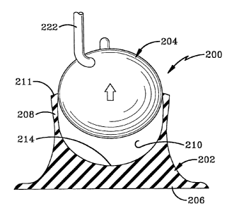
The fifth embodiment of the monitoring device (tag) and patch assembly of
the invention is indicated generally by the numeral 200 in Figs. 10-13.
Assembly
200 generally includes a patch 202 and a monitoring device 204 that includes a
protective body and a monitoring assembly. Patch 202 is generally configured
to
hold monitoring device 204 in a manner that allows monitoring device 204 to be
repeatedly removed from patch 202 and reattached to patch 202 so that
monitoring device 202 may be selectively mounted to tire 71 by selectively
9
CA 02491851 2010-08-02
,
mounting monitoring device 204 to patch 202.
The fifth embodiment of monitoring device 204 has an outer surface that is
rounded or curved in a manner that allows the body to roll as described in US
Patent 6,082,192. The exemplary embodiments of the invention depict monitoring
devices that are free of flat surfaces. The exemplary embodiments in these
drawings
depict a sphere and an oblong sphere although other shapes are contemplated by
the
inventors. Other embodiments of monitoring device 204 may have outer surfaces
that have substantially outer curved or rounded surfaces when the outer
surfaces
include a plurality of small flat surfaces that cooperate to define an outer
rounded
surface. These types of monitoring devices are designed to be placed loosely
within a
tire such that they may roll around being bounded by only the tire and the
rim.
Monitoring device 204 may have the same structure as the monitoring device
disclosed in US Patent 6,082,192. As such, monitoring device 204 and those
having
the same type of configuration (a rounded outer surface) do not have any
features that
may be used to secure them to a patch. Patch 202 of the present invention is
designed
to hold monitoring device 204 in a fixed position with respect to tire 71
without
requiring any special modification to monitoring device 204 that would prevent
monitoring device 204 from being used in a tire in a loose, free rolling
configuration.
Patch 202 includes a base 206 and a tube section 208 that projects up
from base 206. Patch 202 may include a bonding layer 20 as described above.
Tube
section 208 is annular and continuous and defines a cavity 210. Tube section
208
includes a continuous lip 211 that defines an opening 212 that provides access
to
cavity 210. Lip 211 and tube section 208 are free of interruptions, such as
slits, that
would allow lip 211 and tube section 208 to unintentionally open when used
with the
rounded monitoring devices of the invention. The continuity of lip 211
increases the
retaining ability of patch 202 which is important when holding a spherical,
oblong
sphere, or teardrop shaped monitoring device. The continuity of lip 211 also
reduces
the risk that lip 211 will tear during extended use. Tube section 208 tapers
closed
toward lip 211.
The resting position of lip 211 and opening 212 is smaller than the
CA 02491851 2005-01-06
WO 2004/005054
PCT/US2003/020717
maximum width of monitoring device 204 such that opening 212 must be stretched
wider to allow monitoring device 204 to be inserted into and removed from
cavity
210. Lip 211 thus has a closed resting position and an open stretched
position.
Cavity 210 has a depth that is greater than half of the height of monitoring
device
204 such that tube section 208 will close around monitoring device 204 to hold
it
in place. The walls of tube section 208 have sufficient elasticity and
extensibility
such that opening 212 may be stretched open to accommodate monitoring device
204 to seat monitoring device 204 within patch 202 as depicted in Fig. 11. The
elasticity of the walls allows them to return to their resting position to
trap
monitoring device 204 with an interference fit within patch 202. The material
of
patch 202 is configured to retain these properties over time in both hot and
cold
operating conditions. In exemplary embodiments, patch 202 may be fabricated
from any of a variety of thermosets or thermoplastics that have desirable
resiliency
and aged properties.
Opening 212 may be centered about the longitudinal axis of patch 202 such
that opening 212 is directed toward the center of tire 71 when patch 202 is
mounted to tire 71. Centrifugal forces will thus force monitoring device 204
against
patch 202.
The inner surface 214 that defines cavity 210 may be curved to
substantially match the outer curvature of monitoring device 204 as shown in
Fig.
11. In other embodiments of the invention, the inner surface 214 may be
configured such that an air pocket is disposed between base 206 and monitoring
device 204.
In the embodiment of the invention depicted in Fig. 11, monitoring device
204 is oblong and is positioned with its largest diameter substantially
perpendicular
to the longitudinal axis of patch 202. Device 204 may be 3 to 5 percent out of
round to achieve the benefits of an oblong device. The inventors also
contemplate
that patch 202 may be configured to receive monitoring device 204 with the
smallest diameter of monitoring device 204 substantially perpendicular to the
longitudinal axis of patch 202. An oblong configuration helps properly align
monitoring device 204 within patch 202 when vibration forces move monitoring
device 204 with respect to patch 202.
11
CA 02491851 2005-01-06
WO 2004/005054 PCT/US2003/020717
A predictable proper alignment is important when monitoring device 204
has an antenna 218 that is tuned to function better when positioned in a
specific
direction. For example, antenna 218 may be aligned with the longest dimension
of monitoring device 204 so that the user will known the orientation and can
orient
antenna 218 with respect to tire 71.
The proper alignment of monitoring device 204 is also important so that the
breathing tube 219 for the pressure sensor remains positioned within opening
212.
The proper alignment is also important when monitoring device 204 has a
retraction opening 220 that allows a tool or retraction device 222 to engage
monitoring device 204 and pull it from patch 202 as shown in Figs. 12 and 13.
Opening 220 allows at least a portion of device 222 to be inserted into the
body
of device 204 such that device 204 may be pulled from patch 202. Figs. 14 and
depict a sixth embodiment wherein monitoring device 204 is spherical. Another
method of removing monitoring device 204 from patch 202 is to squeeze tube
15 section 208 adjacent base 206 to force monitoring device 204 out of patch
202.
The squeezing force may be used in conjunction with tool 222.
Patch 202 has rounded and curved walls and surfaces that lack points
where stresses are concentrated. The lack of stress concentration increases
the
durability of patch 202. Tube section 208 may also be configured to absorb
vibrational forces. Assembly 200 also has the advantage that monitoring device
204 will not harm tire 71 if monitoring device 204 falls out of patch 202
because
monitoring device is designed to be used loosely within tire 71 and includes
no
sharp edges that could damage tire 71.
The seventh embodiment of the monitoring device (tag) and patch
assembly of the invention is indicated generally by the numeral 300 in Figs.
16-17.
Assembly 300 generally includes patch 202 and an encapsulated monitoring
device 304 having a protective body 305 and a monitoring assembly 306.
Monitoring assembly 306 includes an antenna 307 and the components 308 that
are necessary to monitor and transmit the conditions of the tire.
As described above, patch 202 is generally configured to hold monitoring
device 304 in a manner that allows monitoring device 304 to be repeatedly
removed from patch 202 and reattached to patch 202 so that monitoring device
12
CA 02491851 2005-01-06
WO 2004/005054 PCT/US2003/020717
202 may be selectively mounted to tire 71 by selectively mounting monitoring
device 304 to patch 202. In the seventh embodiment of invention, monitoring
device 304 is teardrop shaped with the rounded head 310 of the teardrop being
held by patch 202 in the manner described above. The tapered tail portion 311
=
of monitoring device 304 extends out of patch 202 into the interior of tire
71.
Antenna 307 of the monitoring system may be positioned in tail portion 311
with components 308 being disposed in head 310. Antenna 307 is parallel to the
longitudinal axis of patch 202. Antenna 307 is thus disposed substantially
perpendicular to the surface of patch 202 that engages tire 71. This
configuration
allows antenna 307 to be disposed radially with respect to tire 71 when patch
202
is attached to the crown portion of tire 71 as depicted in Fig. 16.
Fig. 18 depicts an eighth embodiment of the invention wherein the
monitoring device 320 has a freely extending antenna 307. Antenna 307 extends
straight from patch 202 as described above.
The ninth embodiment of the assembly is indicated generally by the
numeral 350 in Fig. 19. Assembly 350 includes a patch 352 and a monitoring
device 354 that includes a protective body 356 and a monitoring assembly 358.
Ninth embodiment 350 is also teardrop shaped but the head 360 of the teardrop
is threaded to cooperate with threads defined by patch 352 to hold device 354
in
place.
The tenth embodiment of the assembly is indicated generally by the
numeral 400 in Fig. 20. Assembly 400 includes a patch 402 and a monitoring
device 404 that includes a protective body 406 and a monitoring assembly 408.
Monitoring device 404 is the same as monitoring device 354 described above. In
the tenth embodiment, monitoring device 404 is not directly connected to patch
402. In this embodiment, assembly 400 includes an intermediate housing 410
that
is attached to patch 402. Monitoring device 404 is connected to housing 410
when
it is mounted.
Housing 410 may be fabricated from the same material as protective body
406 or another material more rigid than the material of patch 402. In one
embodiment of the invention, housing 410 is encapsulated around the upper
portion of patch 402. In other embodiments, housing 410 may be adhesively
13
CA 02491851 2005-01-06
WO 2004/005054
PCT/US2003/020717
connected or mechanically connected to patch 402.
Housing 410 defines a cavity 412 adapted to receive all of, or a portion of,
monitoring device 404. Housing 410 and monitoring device 404 define
cooperating threads 414 that allow monitoring device 404 to be selectively
attached to and removed from housing 410. In addition to threads 414, any of
the
other attachment arrangements described above may be used without departing
from the concepts of the invention.
While in accordance with the patent statutes, the best mode and preferred
embodiment has been set forth above, the scope of the invention is not limited
thereto, but rather by the scope of the attached claims.
14