Note: Descriptions are shown in the official language in which they were submitted.
CA 02492302 2006-07-26
63632-1607
AUTOMATED NETTER
BACKGROUND OF THE INVENTION
This invention is generally directed to a system
for enclosing materials, such as poultry, hams, or other
materials, in netting and applying a handle and a label to
the package.
The food industry often wishes to place products
in nets. For example, large fowl, particularly turkeys, are
encased in a plastic, see-through wrapper, for sanitary
reasons, and then enclosed in netting for package integrity
and ease of handling. The netting provides a strong
structure to hold the turkey and allows the consumer to see
the packaged material. It is important that the netting be
tight around the package, to provide a pleasing appearance
to consumers. There is a marketing advantage to having
tightly-netted packages.
Nets are also applied to other food products, such
as poultry, hams, sausages, or cheeses, prior to further
processing, such as smoking.
In many cases, a handle is also applied to the
package. Sausages and hams are enclosed in netting prior to
cooking or smoking. The use of a handle is mandated, as
there must be some way to handle the product in the cooking
or smoking apparatus. The handles on these products are
generally discarded after processing.
1
CA 02492302 2005-01-11
WO 2004/007298 PCT/US2003/021745
The handle is also useful to workers and customers in retail establishments,
especially when
the product is frozen, to make it easier to grab the product. A handle
facilitates maneuveririg the
products, such as moving the products in and out of display cases, through
check-out lanes, or in and
out of the consumer's own refrigerator or freezer. Additionally, some
consumers prefer to use a
handle in order to avoid touching the package itself. Accordingly, there is a
marketing advantage
to having a handle on the product. In the case of turkeys or other poultry, it
is important that the
handle be applied at the rear-most point of the birds, which is where the legs
point, to provide a
pleasing appearance to purchasers.
Most of the same products also have a label of some type applied to the
product. The label
displays such data as weight, price per unit of weight, and total price. Other
data, such as lot
numbers, batch identification, product identification, or expiration date, are
also common. The label
can also contain identification information such as brand names or logos.
Netting is manufactured in a long, continuous tube, usually of a hard
thernioplastic but also
from natural fibers. The prior art method of enclosing a turkey in netting was
to clip one end of the
netting tube, place the turkey in the tube, manually pull the netting tightly
around the turkey, clip the
open end to enclose the turkey in the netting, and cut the netting. If a
handle was desired, the
additional step was, after the netting was pulled around the turlcey, to form
a loop while holding the
netting tightly against the turkey, clip the netting at the close of the loop,
and cut the netting.
This prior art method was labor intensive. Additionally, it was difficult to
obtain uniform
tightness of netting. Additionally, the method requires quite a bit of manual
pulling and wrapping,
making hand fatigue and injuries common.
Prior art methods to automate the process have been unsuccessful. One method
used clippers
2
CA 02492302 2006-07-26
63632-1607
built into gathering plates, but that method was awkward and
slow because the gathering plates had to move. Since an
opening must be at least 14 inches to accommodate the
largest turkeys, the gathering plates had to move at least
seven inches and, to be practical, had to move more like
inches. Accordingly, they were big, heavy, and slow.
The prior art automated processes also worked only for
consistently-sized turkeys. Application of a predetermined
length of netting had to be based on the largest turkeys
10 available. If the predetermined length of netting was
sufficient to enclose the largest turkeys, however, all
smaller turkeys would be netted loosely, which caused a
marketing disadvantage.
Accordingly, there is a need for an apparatus and
method of encasing material such as turkeys or hams, in
netting, that will reduce labor costs by reducing the amount
of labor required, easing the tasks of the workers that are
required, and still provide a pleasing appearance to
consumers. There is also a need for an apparatus and method
of encasing material such as turkeys or hams, in netting,
that will provide a loop in the netting to act as a handle,
for subsequent processing or for consumer use. There is
also a need for an apparatus and method of applying a label
with identifying data, as part of the same netting process.
The present invention meets these needs.
BRIEF SUMMARY OF THE INVENTION
In accordance with one aspect of the present
invention, there is provided an apparatus for enclosing
material in a net, comprising a roll of netting, said roll
having an open end and a closed end, means to place material
in said netting through said open end of said roll, first
gathering means to gather said netting around said material,
3
CA 02492302 2006-07-26
63632-1607
second gathering means to gather said netting around said
material, means for moving said second gathering means
relative to said first gathering means, whereby said netting
is stretched between said first gathering means and said
second gathering means, a first clipper to close and sever
said netting at said first gathering means, to create a new
closed end on said severed roll, a handle maker to form a
loop from said stretched netting, and a second clipper to
close said loop at said second gathering means.
In accordance with a second aspect of the present
invention, there is provided an apparatus for enclosing
material in a net, comprising: a frame; a product tube
carried by said frame, and adapted for receiving a net and
for maintaining a first end of said net in an open position,
a second end of said net being in a closed position, whereby
the material to be enclosed can be conveyed from a first end
of said product tube to engage said second end of said net
at a second end of said product tube and unfurl a portion
off said net from said product tube; a first iris held by
said frame adjacent to said second end of said product tube
and adjustable from an open position forming an aperture
larger than the material, to a substantially closed
position, whereby the material and said portion of engaged
and unfurled net can be conveyed from said second end of
said product tube through said first iris aperture and
whereby first iris gathers said engaged and unfurled net in
said substantially closed position; a second iris mounted on
said frame and movable from a first position adjacent said
first iris, to a second position remote from said first
iris; said second iris being adjustable from an open
position forming an aperture larger than the material, to a
substantially closed position, whereby said second iris
gathers said engaged and unfurled net in said substantially
4
CA 02492302 2006-07-26
63632-1607
closed position; a tray mounted on said frame and movable
from a first position protruding through said first iris and
said second iris, to a second position remote from said
first iris; a first clipper attached to said first iris and
positioned to clip and sever the net gathered by said first
iris and said second iris when said second iris is in said
second position remote from said first iris, to form said
closed position of said second end of said net on said
product tube and a gathered strand of net on the material; a
clamp rotatably attached to said frame to grasp said
gathered strand and to rotate to form a loop in the gathered
and severed net; a second clipper attached to said second
iris and positioned to clip said loop to form a handle on
the net on the material.
In accordance with a third aspect of the present
invention, there is provided an apparatus for enclosing
material, comprising: a net; a frame; a product tube
carried by said frame, receiving said net, and maintaining a
first end of said net in an open position, a second end of
said net being in a closed position, whereby the material to
be enclosed can be conveyed from a first end of said product
tube to engage said second end of said net at a second end
of said product tube and unfurl said net from said product
tube; a first iris held by said frame adjacent to said
second end of said product tube and adjustable from an open
position forming an aperture larger than the material, to a
substantially closed position, whereby the material and said
portion of engaged and unfurled net can be conveyed from
said second end of said product tube through said first iris
aperture and whereby first iris gathers said engaged and
unfurled net in said substantially closed position; a second
iris mounted on said frame and movable from a first position
adjacent said first iris, to a second position remote from
4a
CA 02492302 2006-07-26
63632-1607
said first iris; said second iris being adjustable from an
open position forming an aperture larger than the material,
to a substantially closed position, whereby said second
iris gathers said engaged and unfurled net in said
substantially closed position; a tray mounted on said frame
and movable from a first position protruding through said
first iris and said second iris, to a second position remote
from said first iris; a first clipper attached to said first
iris and positioned to clip and sever the net gathered by
said first iris and said second iris when said second iris
is in said second position remote from said first iris, to
form said closed position of said second end of said net on
said product tube and a gathered strand of net on the
material; a clamp rotatably attached to said frame to grasp
said gathered strand and to rotate to form a loop in the
gathered and severed net; a second clipper attached to said
second iris and positioned to clip said loop to form a
handle on the net on the material.
Embodiments of the present invention disclose an
apparatus and a method to insert material such as a turkey
into netting, to pull the netting tightly around the
material, to form a loop at one end for carrying the
material, and to apply a label with data concerning the
material. The apparatus and method described accomplish
this purpose, and allow for encasing not just whole turkeys
but also turkey breasts, hams, sausages, cheeses, and any
other materials which one might desire to place in netting.
The method and apparatus provide for pulling the netting
tight by machinery, instead of by hand, easing the task of
the worker and providing for a uniformly tight appearance.
The apparatus comprises a product tube, a first
clipper, a handle-maker, and a second clipper. The
apparatus places the material to be enclosed in a continuous
4b
CA 02492302 2006-07-26
63632-1607
cylinder of netting, previously clipped on one end. The
apparatus pulls the material through two irises, pulling the
netting about the material. The two irises then close,
gathering the netting. One iris moves away, tightening the
netting about the material. The handle maker grasps the
gathered netting, pulling it tightly around the material,
and further makes a loop. The first clipper clips the
netting and also severs it. The second clipper clips the
loop adjacent the material, to enclose the material in a
tight net with a looped handle. The second clipper also
clips a label to the loop, for product information.
A general object of embodiments of the present
invention is to provide a method and apparatus for encasing
materials very tightly in netting, to reduce labor costs and
injuries and to obtain an uniform appearance.
Another object of embodiments of the present
invention is to provide a method and apparatus to encase
materials very tightly in netting and automatically to apply
a label with identifying data concerning the packaged
materials.
Another object of embodiments of the present
invention is to provide a method and apparatus to encase
materials very tightly in netting and to apply a loop in the
netting, to act as a handle for further processing or for
consumer use.
Another object of embodiments of the present
invention is to provide an apparatus and method that
accommodate variations in size of materials to be encased.
Another object of embodiments of the present
invention is to provide an apparatus and method to make the
hocks of turkeys point in the correct direction.
4c
CA 02492302 2005-01-11
WO 2004/007298 PCT/US2003/021745
BRIEF DESCRIPTION OF THE SEVERAL VIEWS OF THE DRAWINGS
The organization and manner of the structure and operation of the invention,
together with
further objects a.nd advantages thereof, may best be understood by reference
to the following
description, taken in connection with the accompanying drawings:
FIGURE 1 is a front perspective view of the apparatus of the preferred
embodiment of the
present invention.
FIGURE 2 is an elevation view of the apparatus of the preferred embodiment of
the present
invention.
FIGURE 3 is a rear perspective view of the apparatus of the preferred
embodiment of the
present invention.
FIGURE 4 is a view of the first iris plate of the apparatus of the preferred
embodiment of the
present invention.
FIGURE 5 is a view of the first clipper of the apparatus of the preferred
embodiment of the
present invention.
FIGURE 6 is a view of the moving iris plate of the apparatus of the preferred
embodiment,
of the present invention.
FIGURE 7 is a view of the second clipper of the apparatus of the preferred
embodiment of
the present invention.
FIGURE 8 is a view of the dump tray of the apparatus of the preferred
embodiment of the
present invention.
FIGURE 9 is a view of the handle maker of the apparatus of the preferred
embodiment of the
present invention.
5
CA 02492302 2006-07-26
63632-1607
FIGURE 10 is a view of sample labels of the
preferred embodiment of the present invention.
DETAILED DESCRIPTION OF THE ILLUSTRATED EMBODIMENT
While the invention may be susceptible to
embodiments in different forms, there is shown in the
drawings, and herein will be described in detail, a specific
embodiment with the understanding that the present
disclosure is to be considered an exemplification of the
principles of the invention, and is not intended to limit
the invention to that as illustrated and described herein.
For example, the present disclosure describes the method and
apparatus as used to encase whole turkeys. The same method
and apparatus can be used for other whole poultry, for
poultry parts, such as turkey breast, or for any other
material that one may wish to enclose in netting, such as
hams, sausages, cheeses, or other food or non-food products,
without departure from the invention.
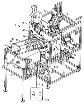
The apparatus 2, as shown in FIGURES 1, 2, and 3,
is built with a frame 4 having a front 6, rear 8, left 10,
and right 12. Attached to the frame are a product tube 30,
a first iris plate 60, a moving iris plate 132, a tray 202,
an orienter, a handle maker 230, a printer 260, an air
supply, and electronic controls 276. A scale 16 is located
apart from but close to the front of the frame 6.
The product tube 30 is a standard pneumatic tube,
open at both ends, and is attached to the front of the
frame 6. In one embodiment, the product tube 30 is oriented
to slope down slightly toward the rear 8, so that products,
such as turkeys, placed in the upper end of the product
tube 30 will slide by gravity the length of the product
tube 30 and into the netting area of the apparatus 2, as
6
CA 02492302 2006-07-26
63632-1607
explained below. In another embodiment, a roller tray is
placed inside the product tube 30, to allow products, such
as hams, to roll the length of the product tube 30 and into
the netting area of the apparatus 2, as explained below.
In the preferred embodiment, the product tube 30
is oval in cross-section and is of a sufficient height and
width to accommodate the largest turkeys. Any suitable
cross-section and size will suffice, depending on the
material to be netted. In one embodiment, the product
tube 30 has two tube guides located on the inside, to keep
turkeys oriented in the proper direction as they slide the
length of the product tube 30. Similar tube guides can be
used for other products. Alternatively, a product tube
circular in cross-section can be used for cylindrical
products such as sausages. A roller tray, a conveyor belt,
robotic arms, or any other means for delivering the
materials to be encased into the apparatus 2 can be used.
The netting 38 is, in the preferred embodiment,
comprised of a hard but flexible plastic. It is
manufactured in a cylindrical shape and rolled into a torus.
One end of the roll of netting 38 is clipped to close it and
the roll is then placed around the outside of the product
tube 30. A brake ring 40 is used to hold the netting 38 in
place. In the preferred embodiment, the brake ring 40
comprises a flexible cable, attached to an air cylinder, and
surrounding the netting 38 on the product tube 30. The air
cylinder actuates to tighten the cable to hold the
netting 38 snugly to the product tube 30, or releases to
loosen the cable around the netting 38. After material such
as a turkey has traveled down the product tube 30, contacted
the netting 38, and landed on the dump tray 206, as later
explained, the air cylinder actuates, tightening the cable,
and providing resistance to further unfurling of the
7
CA 02492302 2006-07-26
63632-1607
netting 38. The air cylinder shuts off after the turkey has
been clipped, as later explained, loosening the cable and
freeing the netting 38 for unfurling by the next turkey. In
another embodiment, the brake ring 40 is a flexible rubber
hose, attached to an air supply, surrounding the product
tube 30 to hold the netting 38 in place. A simple rubber
band can also be used to hold the netting about the product
tube.
7a
CA 02492302 2005-01-11
WO 2004/007298 PCT/US2003/021745
The product tube 301eads to a first iris plate 60. The first iris plate 60,
shown in more detail
in FIGURE 4, comprises a vertically oriented sheet of material containing a
first iris 62. The first
iris 62 comprises three separators 64a, 64b, and 64c; which are actuated by a
first iris separator
cylinder 66. A first iris left gate assembly 68 and a first iris right gate
assembly 72 are attached to
the rear of the first iris plate, as shown in FIGURE 5. These two gate
assemblies are actuated by a
first iris left gate cylinder 70 and a first iris right gate cylinder 74. The
three separators 64a, 64b, and
64c operate like a camera lens, to open to allow material, such as a turkey,
to pass through it, and to
close to gather the netting 38. The first iris left gate assembly 68 and the
first iris right gate assembly
72 rotate inwardly to further gather the netting 3 8 and retract to allow
material, such as a turlcey, to
pass through the first iris 62. FIGURE 5 shows the first iris left gate
assembly 68 and a first iris right
gate assembly 72 rotated inward to the closed position.
A first clipper 102, shown in FIGURE 5, is attached to the first iris plate
60. The first clipper
102 is actuated by a first clipper main cylinder 104 and has a first clipper
die support 106. A lcnife
108 is also attached to the first iris plate 60 and is actuated by a knife
cylinder 110. The first clipper
102 clips the netting 38 after it has been gathered by the first iris 62 and
the first iris left gate
assembly 68 and the first iris right gate assembly 72. The knife 108 severs
the netting 3 8 after it has
been clipped.
To the rear of the first iris plate is a moving iris plate 132, shown in
FIGURE 6. The moving
iris plate 132 is moved by a moving iris plate cylinder 134. The moving iris
plate 132 travels along
four traveling rods 148a, 148b, 148c, and 148d, which are attached to the
first iris plate 60 and to
the frame 4, so that the moving iris plate 132 is always parallel to the first
iris plate 60.
The moving iris plate 132 comprises a vertically oriented sheet of material
containing a
8
CA 02492302 2005-01-11
WO 2004/007298 PCT/US2003/021745
moving iris 130, The moving iris 130 comprises three separators 136a, 13 6b,
and.136c, and operates
like a camera lens, to open to allow material, such as a turkey, to pass
through it, and to close to
gather the netting 38. The separators 136a, 136b, and 136c are actuated by a
moving iris separator
cylinder 134.
To accommodate the largest turkeys, an opening must be 14 inches in diameter.
The use of
three separators 136a, 136b, and 136c in the moving iris 130 and three
separators 64a, 64b, and 64c
in the first iris 62 allows for use of actuating cylinders 66 and 13 8 with
only a four-inch movement,
which can be operated quickly to achieve high production rates.
A moving iris left gate assembly 140 and a moving iris right gate assembly 144
are attached
to moving iris plate 132 at the front of the moving iris 130, as shown in
FIGURE 7. These two gate
assemblies 140 and 144 are actuated by a moving iris left gate cylinder 142
and a moving iris right
gate cylinder 146. The moving iris left gate assembly 140 and a moving iris
right gate assembly 144
operate in the same manner as described above for the first iris plate 60: the
moving iris left gate
assembly 140 and a moving iris right gate assembly 144 rotate inward to gather
the netting and rotate
outward to allow material, such as a turkey, to pass through the moving iris
130.
A second clipper 160, shown in FIGURE 7, is attached to the moving iris plate
132. The
second clipper 160 is actuated by a second clipper cylinder 164 and contains a
die support 166. The
second clipper 160 clips the netting 38 after it has been gathered by the
moving iris 130 and the
moving iris left gate assembly 140 and a moving iris right gate assembly 144.
When a handle is
desired on the package, the second clipper 160 clips the netting after it has
been gathered and after
the handle maker 230, described below, has formed a loop in the netting 38.
Note that, in the
preferred embodiment, the second clipper 160 contains a reel brake 162 to hold
the clips tightly and
9
CA 02492302 2005-01-11
WO 2004/007298 PCT/US2003/021745
to prevent shaking of the clips as the second clipper 160 travels.
To the rear of the moving iris plate 132 is the tray 202, shown in FIGURE 8.
The tray 202
is mounted to the traveling rods 148a, 148b, 148c, and 148d and moves in a
front to rear direction,
actuated by a tray cylinder 204. Mounted on top of the tray 202 is a dump tray
206, which is
actuated by a dump tray cylinder 212. The dump tray 206 is sized to
accommodate the material
being netted. In one embodiment, the dump tray 206 contains a dump tray eye
that senses when
material arrives on the dump tray 206. In another embodiment, the dump tray
206 contains two pan
flanges, to control the orientation of the turlcey on the dump tray 206.
When the tray 202 is in its most forward position, the dump tray 206 protrudes
through the
moving iris 130 and the first iris 62, which are open. Material, such as a
turlcey, slides down the
product tube 30, contacts the closed end of the roll of netting 38, moves
through the first iris 62 and
the moving iris 130, pulling the netting 38 along, and lands on the dump tray
206. The moving iris
130 and the first iris 62 then close to gather the netting 38 as described
above. The tray 202 then
retracts to the rear, taking along the dump tray 206 and the turkey, and
slightly tightening the netting
3 8 around the turkey.
The handle maker 230, shown in FIGURE 9, is comprised of a handle maker clamp
232, a
rotating cylinder 234, a clamping cylinder 236, a lifting cylinder 238, a
first prox switch 240, a
second prox switch 242, and a vacuum assembly 262. The handle malcer. 230 is
located just to the
rear and just below the first iris plate 60. The rotating cylinder 234 causes
the handle malcer clamp
232 to rotate in a horizontal plane. The lifting cylinder 238 causes the
handle maker 230 to arise and
descend vertically. The clamping cylinder 236 causes the handle maker clamp
232 to open and
close. The two prox switches 240 and 242 sense the location and limits of
movement of the handle
CA 02492302 2005-01-11
WO 2004/007298 PCT/US2003/021745
maker clamp 232.
The handle maker 230 ascends after the netting 38 has been gathered and the
netting 38 is
stretched inside the open handle maker clamp 232. The handle maker clamp 232,
when actuated,
closes to grasp the netting 38. After the first clipper 102 has clipped the
netting 38 and the knife 108
has severed the netting 38, the handle maker 230 rotates, actuated by the
rotating cylinder 234, to
form a loop in the netting 38. The second clipper 160 then clips the netting
38 to close the netting
around the turkey and to form a handle in the netting 38.
The printer 260 is located below the product tube 30. It is a standard printer
of any suitable
manufacture, so long as it is capable of printing labels 266. The labels 266,
shown in FIGURE 10,
comprise a label body 268, a label neck 270, and a perforation 272. A tag
clamp 264 grabs a label
266 as it exits the printer 260, pulls on the labe1266 to tear it at the
perforation 272, and places the
label 266 on top of the handle maker clamp 232. A vacuum assembly 262 holds
the labe1266 in
place. When a label 266 is desired, the label neck 270 protrudes next to the
netting 3 8. The second
clipper 160, when it clips the netting as described above, clips both netting
38 and the label neck
270, so that the label 266 is securely fastened to the package.
The scale is placed at a convenient location near the front of the frame 6.
The scale
communicates with the printer 260 through a scale cable 18. The weight of the
material, such as a
turkey, is transmitted to the printer 260. When the printer 260 prints the
label 266, it can add the
weight of the turkey as well as any other data that is desired.
All moving parts are actuated by air cylinders as described above. Each air
cylinder is
connected to a standard air supply (not shown). An electronic control 276
monitors and operates the
apparatus 2 by controlling the various cylinders. In the preferred embodiment,
the electronic control
11
CA 02492302 2005-01-11
WO 2004/007298 PCT/US2003/021745
is a standard Siemens central processing unit, with a "power 5 6EP1333-1SL11"
power supply, a
"Simatic S7-300 314-1AE04-OABO" PLC, a 32-output "SM322 321-1 BL00-OAAO" card,
a 32-input
"SM 321 321-ABL00-0AA0" card, and a 16-input "SM 321 321-1BHOS-OAAO" card.
All moving parts are enclosed by doors (not shown) with limit switches (not
shown) to sense
the position of the doors. For safety, the entire apparatus will stop all
movement if a door is opened.
In the preferred embodiment, a Banner Machine Safety GM-FA-10J module monitors
and controls
all limit switches.
Please note that the clippers 102 and 160 have unique features. To achieve the
objects of the
invention, the clippers 102 and 160 must have long gates, the cylinders 104
and 164 must be offset
to the side instead of being right over the clip channel (to save room), the
punch holder must be
offset to the center line of the punch (to shorten the height of the apparatus
2 in order to fit into
standard rooms), and the punch, which is a standard wear item, must be able to
be changed in about
one minute, instead of the usual 30 minutes change time.
To begin operation of the apparatus 2, the netting 38 is placed over the
product tube 30. The
netting 38 is clipped in a standard manner, at the rear of the product tube
30. At this point, both
irises 62 and 130 are open, the moving iris plate 132 is moved to its most
forward position, just
behind the first iris plate 60, the tray 202 has moved to its most forward
position, and the dump tray
206 protrudes through the eyes of each of the irises 62 and 130. The handle
maker 230 is at its
recessed or most downward position.
The material to be netted, such as a dressed and wrapped turkey, is placed on
the scale 16.
The scale 16 weighs the product and transmits this data to the printer 260.
The printer 260 prints a
label 266 with whatever data is required, such as weight, cost per pound, and
total cost. The printer
12
CA 02492302 2006-07-26
63632-1607
96 ejects the label 266, whereupon the tag clamp 264 grasps
the label 266, tears it at the perforation 272, and places
it on the handle maker clamp 232. The vacuum assembly 262
draws a slight vacuum through two small holes on the handle
maker clamp 232, to keep the label 266 in place.
In the meantime, the operator takes the turkey off
the scale and places it in the product tube 30. Because of
the downward slant of the product tube 30, the turkey slides
down the product tube 30. If it fails to slide, a slight
push by the operator will propel it. For this reason, the
product tube is longer than a person's arm, to keep the
operator's hands out of any moving parts. The turkey slides
against the clipped end of the netting 38, through the first
iris 62 and the moving iris 130, and onto the dump tray 206.
The dump tray eye 214 senses the arrival of the turkey and
signals the electronic control 276. Since the end of the
netting 38 had been clipped, the turkey pulls the netting 38
along with it. The brake ring 40 prevents the netting 38
form unrolling too much and maintains a slight amount of
tension on the netting 38.
The tray 202 then moves toward the rear, taking,
of course, the dump tray 206 and the turkey with it, moving
an amount sufficient to clear both irises 62 and 130. The
orienter now descends and pushes down on the turkey. If the
turkey is askew, the orienter forces the legs of the turkey
to point toward the front 6, as that is where the handle
will be applied. Both irises 62 and 130 close, somewhat
gathering the netting 38. The orienter then ascends back to
its original position. The moving iris plate 132 and the
tray 202 then move to the rear, pulling the netting 38
through the now-closed moving iris 130 and tautening the
netting 38 around the turkey. Please note that the
traveling components, the moving iris plate 132 and the
13
CA 02492302 2006-07-26
63632-1607
tray 202, only move as far to the rear as is necessary, and
merely make the netting 38 snug around the turkey, not
tight.
The handle maker 230 now rises and the handle
maker clamp 232 closes, grasping the netting
13a
CA 02492302 2005-01-11
WO 2004/007298 PCT/US2003/021745
38. The first iris left gate assembly 68 and first iris right gate assembly 72
rotate toward the center
of the first iris 62, further grasping the netting 3 8.
The first clipper 102 now fires to clip the netting 3 8 at the point where it
is grasped in the
center of the first iris 62. As soon as the first clipper 102 fires, the knife
108 cuts the netting 38 just
to the rear of the newly-applied clip.
The handle maker 230 now rotates 180 degrees horizontally to malce a loop out
of the
gathered netting 38. The moving iris plate 132 moves forward slightly, about
five inches, in order
to provide enough slack for the handle maker clamp 232 to rotate. When the
handle maker 230
rotates, it pulls the netting 38 tightly around the turkey. This step allows
the apparatus 2 to
accommodate any size of turlcey and still obtain a tight fit of netting 3 8.
As soon as the handle maker clamp 232 has rotated 180 degrees, as sensed by
the prox
switches 240 and 242, the moving iris left gate assembly 140 and moving iris
right gate assembly
144 rotate toward the center of the moving iris 130, further grasping the
netting 38. The netting 38
is now gathered by the moving iris 130 and by the moving iris left and right
gate assemblies 140 and
144, so that the netting 38 tightly encloses the turkey, then forms a loop
around the handle maker
clamp 232 and extends back in between the moving iris left and right gate
assemblies 140 and 144
to form a loop. The neck 270 of the labe1266 also extends into this same area.
The second clipper 160 now fires, clipping the netting 38 and labe1266
together. The handle
maker clamp 232 then descends to its original, downward position and rotates
back to its original
orientation, the tray 202 and the moving iris plate 132 move to the most
rearward position, all gate
assemblies 68, 72, 140, and 144 rotate back to their original, open positions,
and both irises 62 and
130 open.
14
CA 02492302 2005-01-11
WO 2004/007298 PCT/US2003/021745
The dump tray 206 then rotates to the right, dumping the now-netted turkey out
of the
apparatus 2. The dump tray 206 then retracts to its original, level position
and the tray 202 and
moving iris plate 132 move forward to their original positions. The dump tray
206 then moves
forward into its original position inside the now-open irises 62 and 130. The
apparatus 2 is now
ready for another turkey.
Please note that many variations can be made of this method without departing
from the
invention. For example, the dump tray 206 can dump the netted turlcey out
either the left or right
side of the apparatus 2, or even out the rear, depending on the user's needs.
The handle maker step
can be eliminated if no handle is desired, or the label step can be eliminated
if no label is desired.
While a preferred embodiment of the present invention is shown and described,
it is
envisioned that those skilled in the art may devise various modifications of
the present invention
without departing from the spirit and scope of the appended claims.