Note: Descriptions are shown in the official language in which they were submitted.
CA 02492513 2005-O1-14
WO 2004/009444 PCT/NL2003/000506
Modular alle~for an aircraft or train as well as wall and module for such a
galley and
aircraft or train equipped therewith
The present invention relates to a modular galley for an aircraft or train.
Such modular galleys are l~nown. For aircraft in particular these galleys are
fully
assembled by specialist suppliers so that they can then be fitted as a unit in
the aircraft.
Such galleys consist of a frame, the dimensions of which are dictated by the
dimensions of
the aircraft at the location where the galley is to be installed, as well as a
multiplicity of
modules permanently fixed to the frame. In accordance with the state of the
art, and also in
accordance with the invention, these modules can comprise cupboards, ovens,
cooling
installations, such as refrigerators or insulated cabinets provided with a
cooling medium,
water supplies, coffee machines, ovens, water boilers, etc. Connections to the
water supply,
power supply or air supply are needed for a number of such modules. These
connections
are made permanently using methods that are non-standard or at least are
hardly standard.
The various aspects mean that for an aircraft such a galley, as it is l~nown
in aircraft circles,
is a fixed unit that once it has been installed remains in place in the
aircraft and camiot be
adapted specifically to the wishes of the passengers. In practice it is found
that the wishes
of the passengers are usually dependent on the route on which the aircraft is
employed. In
the case of aircraft galleys, just as with other systems, components etc. to
be installed in an
aircraft, it is extremely important that the various components are fixed to
the aircraft in a
very reliable manner or that it is ensured in some other way that at least
nothing is able to
float around the aircraft during turbulent flying conditions or in emergency
situations.
The disadvantage of the l~nown galleys is that there is no uniformity of
construction
between the various galleys for diverse types of aircraft - connections are
always made and
assembly is always carned out more or less as the engineer sees fit when
building the
prototype -, that the galley cannot be adapted depending on the wishes of the
passengers -
therefore, galleys are usually used that have more or less standard equipment
per airline -
and that re-equipping or modifying the equipment of a galley is not possible
other than
during maintenance of the aircraft by specialist personnel since the galley
and the modules
are fixed permanently, or at least such that they cannot easily be uncoupled,
in the aircraft.
The aim of the present invention is to provide a galley, as it is lrnown in
aircraft
circles, for an aircraft or train, which galley can easily be re-arranged,
optionally per flight
CA 02492513 2005-O1-14
WO 2004/009444 PCT/NL2003/000506
2
or run, or at least can be adapted to the anticipated desires of the
passengers on that flight
or run. A further aim in this context is to standardise the galley to a
greater extent.
The abovementioned main aim is achieved according to the invention by
providing a
modular galley for an aircraft or train, comprising:
~ a wall provided with a multiplicity of guides ntmling in the vertical
direction with
undercut slots;
~ a multiplicity of modules with runners on the rear that can be acconunodated
in the
undercut slots;
~ lifting means for raising or lowering a said module, the runners of which
have been
accommodated in a said undercut slot, over the wall.
By providing a wall with a multiplicity of guides naming in the vertical
direction
with undercut slots and the galley modules, which preferably are essentially
in the form of
a block but also can very well be in the form of a worktop or a seat - that
can be wall-
mounted - for crew, to be provided at the rear with runners than can be
accommodated in
said undercut slots, as well as providing lifting means, it becomes possible
to hook the
galley modules by means of their undercut runners into an undercut slot and
then to bring
these to the correct height with respect to the wall by means of the lifting
means. As soon
as the undercut runners have been hooked into the undercut slots, the galley
module is then
attached to the wall and, except for the possibility of sliding along the
slot, also fixed to the
wall. With this arrangement the lifting means enable easy and rapid assembly
without
special tools, for example for bringing a galley module that is to be mounted
high to the
right height and position correctly in front of the wall. With this
arrangement the runners
can optionally be so constructed that they can be inserted in the slot in such
a way that they
can then be hooked into the undercut part of the slot by means of a
projection, which can be
swung inwards against resilient force to allow insertion in the slot. The
guide with undercut
slots can be rails mounted on the wall - projecting outwards with respect to
the plane of the
wall -, but can equally well be sunlc in the wall, for example rails sunk in
the wall or slots
made directly in the wall. The wall can be either a fixed wall or a movable
wall.
In order to ensure reliable, rattle-free fixing of the modules to the wall it
is preferable
according to the invention if the nuzners are of undercut construction
corresponding to the
slots. This is understood in particular to mean that, viewed in the horizontal
plane, the
runners have a cross-sectional shape that corresponds to the cross-sectional
shape of the
CA 02492513 2005-O1-14
WO 2004/009444 PCT/NL2003/000506
3
undercut slots, viewed in the horizontal plane.
With a view to reliable fixing of the modules to the wall and a simple
procedure for
this as well as a simple procedure for uncoupling the modules from the wall,
it is preferable
according to the invention if the slots are widened in places such that, on
the one hand, a
said undercut runner can be inserted here, essentially unimpeded, in the
horizontal direction
so as then to hook into the respective undercut slot after being moved
vertically and that,
on the other hand, the runner hooking into the slot can be removed from the
slot in the
horizontal direction after it has been positioned in the widened pa~.-t of the
slot. In this way
it becomes possible, inter alia, to construct the runner as a component
without moving
parts, such as a moving proj ection. This males functioning of the runner more
reliable, in
which context it must be borne in mind in particular that the runner is also
an important
component in locking the module to the aircraft. All that is needed to fix the
module is for
the runners of the module to be inserted via a widened section into one or
more slots and
then for the module to be moved, with or without the aid of the lifting means,
along the
slot, as a consequence of which the runners will hook into the undercut slot.
Precisely the
reverse procedure is adopted for removing a module from the wall; the module
will be
positioned, with or without the aid of the lifting means, such that the
runners are in a
widened section of the slot, after which tile module can easily be removed
from the wall.
In order further to facilitate the mounting of modules on the wall and the
removal of
modules from the wall, in particular so that the physical exertion of the
personnel required
is as Iow as possible, it is preferable according to the invention if the
widened sections of
the slots are provided close to the floor, such that a module placed on the
floor, optionally
also supported by a mobile platform, can be moved over the floor and placed in
contact
with the wall so that the runners project into the slot via the widened
sections - lifting
operations are not necessary for this - so as then to be able to raise the
module up the slot to
the desired mounting height with the aid of the lifting means. With this
arrangement it will,
in particular, be the case that the widened sections of the slots are at a
height above the
floor of the galley such that a module placed on the floor in front of the
slot concerned
completely overlaps the widened section.
According to a further advantageous embodiment of the invention, the slots,
viewed
in a horizontal plane, have an essentially T-shaped form, the leg of the T
pointing away
from the wall. Tn this way a slot is obtained that as it were is undercut on
two sides, which
CA 02492513 2005-O1-14
WO 2004/009444 PCT/NL2003/000506
4
males it possible, in particular, reliably to prevent a module mounted on the
wall from
swinging with respect to the wall in the horizontal plane about an essentially
vertical axis.
A fiu-ther requirement for this is that the runners on the module are
constructed such that
they are essentially undercut on two sides. An undercut of the runners on two
sides can be
achieved either by constructing each rumier with an undercut on two sides -
which is
preferred - or by working with pairs of runners in each case, one of which,
for example, is
constructed with an undercut on the left and the other of which, for example,
is constructed
with the undercut on the right. According to a particularly preferred
embodiment, the
runners will be shaped life a mushroom.
It will be clear to those skilled in the art that the lifting means can be
constructed in a
wide variety of ways that fall within the scope of the claims. However, it is
preferable to
construct the lifting means such that they are reliable in operation and of
simple
construction. This can be achieved according to the invention if the lifting
means comprise
a spindle - provided with external screw thread - that runs vertically in the
wall with a
lifting arm that projects from the wall and can be moved along the spindle by
means of
matching internal screw thread. The spindle can be driven in a wide variety of
ways to
make it rotate, for example manually, but it will preferably be driven by a
motor, for
example by means of an electric motor. With this arrangement the number of
revolutions
that the spindle males is proportional to the vertical height over which the
lifting arm is
raised or lowered. Such operation can easily be automated.
According to yet a further embodiment it is preferable if the modular galley
furthermore comprises locl~ing means that are provided on the wall and on each
module
and interact with one another, for fixing a said module at a speciftc height.
Such locking
means can be constructed in a wide variety of ways and male it possible for
the lifting
means to be uncoupled from the module after the module has been brought to the
desired
height so as to use these lifting means, for example, for bringing a
subsequent module
located below or optionally above to the correct height. According to the
invention, the
locl~ing means can comprise a pin that is provided on the wall or the module
and can be
slid outwards in the horizontal direction, as well as a pin seat provided in
the module or the
wall - depending on where the pin is provided. The pin then as it were shoots
or slides out
of the wall or the module into the pin seat provided on the other part - the
module or the
wall - so as thus to fix the module on the wall in the vertical direction.
CA 02492513 2005-O1-14
WO 2004/009444 PCT/NL2003/000506
In order, insofar as is necessary, easily to be able to provide the modules
with a gas,
such as air, water, data and/or power, or, if appropriate, easily to be able
to discharge a gas
or water or to be able to output data from a module, it is preferable
according to the
invention if the wall and one or more of the modules are provided with
connecting means
5 for gas, water, data exchange and/or power. In this context the wall will,
in particular, be
provided with a connection unit equipped with a gas supply connector, a gas
discharge
connector, water supply connector, water discharge connector and a power
connector and
data communication bus. Depending on what is housed in the module, the module
can then
be provided with a matching gas supply connector and/or gas discharge
connector and/or
water supply connector andlor water discharge connector and/or power
comiector. What
this then comes down to is that, as it were, an assembly of plug and socket is
provided with
connectors that can simply be pushed into one another. Such connectors that
can simply be
pushed into one another are known per se from the state of the art and do not
require any
further explanation for those spilled in the art.
According to a further embodiment, the modular galley according to the
invention
comprises a number of vertical sections alongside one another, with, per
section;
~ at least two of said slots;
in the wall, at least one gas supply, gas discharge, water supply, water
discharge and
power connector; and
~ lifting means.
What is achieved by providing two slots per section is that a module can in
each case be
fixed to the wall via runners hooking into two slots, which is beneficial for
the reliability of
the fixing. As a result of providing lifting means per vertical section it is
not necessary to
move lifting means between the sections, which appreciably increases the ease
of use when
fitting and removing modules. By providing the wall per vertical section with
every type of
connection that can be needed, great freedom of arrangement is achieved with
regard to the
distribution of various types of modules over the wall.
According to yet a further embodiment of the invention, the modular galley has
one
or more service trolleys placed underneath a said module. Service trolleys are
trolleys
which are wheeled through the aircraft cabin to provide the passengers with
snacks.
According to a further aspect, the present invention relates to a wall for a
modular
galley according to the invention and to an aircraft or train provided with
such a wall.
CA 02492513 2005-O1-14
WO 2004/009444 PCT/NL2003/000506
6
According to yet a further aspect, the invention relates to a module for a
modular
galley according to the invention.
According to yet a further aspect the present invention relates to an aircraft
or train
provided with a wall according to the invention or with a modular galley
according to the
invention.
The present invention will be explained in more detail below with reference to
an
example shown highly diagrammatically in the drawing. In the drawing:
Figure I shows a diagrammatic, perspective view of a modular galley according
to
the invention;
Figure 2 shows, diagranunatically, a horizontal section of a detail according
to the
line II-II from Figure l; and
Figure 3 shows a diagrammatic view of the rear of a module, also termed galley
module, according to the invention.
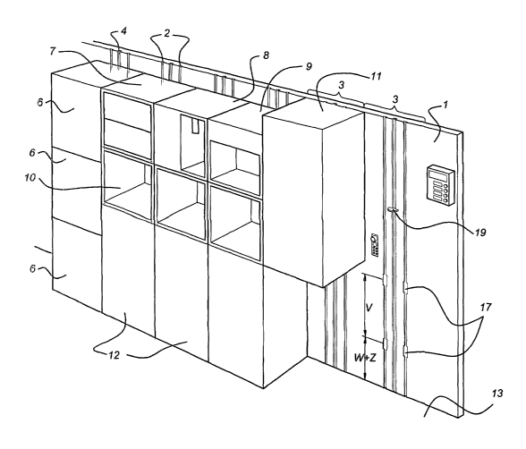
With reference to, in particular, Figures 1 and 2, a wall l, termed system
wall, is
shown. The system wall 1 is so to say sub-divided into vertical sections 3,
six in the present
case. Each vertical section 3 is provided with two slots 2 and a spindle 4.
Here, per section
3, the spindle 4 is in each case fitted between two slots 2. However, it will
be clear to those
skilled in the art that it would be possible to work with one slot or with
more than two slots
2 per section acid that the spindle 4 does not necessarily have to be central,
although this
will be preferred.
As can be seen in particular in Figure 2, each slot 2 has a T-shaped cross-
section
viewed in the horizontal plane, the so-called leg of the T-shape pointing away
from the
wall 1 so as thus to obtain a slot that is undercut on two sides.
The spindle 4 consists of a rod provided with external screw thread, on which
a bush
5, which is provided with internal screw thread and externally has a non-
circular peripheral
shape, is provided. This bush is accommodated in a vertical guide 50 and
because of its
non-circular peripheral shape will be prevented from rotating in the vertical
guide 50. The
bush 5, in turn, supports a lifting arm 19 that projects from the wall 1.
Again with reference to, in particular, Figure 1 it can be seen that a number
of
modules 6, 7, 8, 9, 10 and 11 have been mounted on the wall 1. As is indicated
by the
different reference numerals, these modules are of various types and/or of
various sizes.
The modules 6 are, for example, all cabinet modules with a door that can be
opened and
CA 02492513 2005-O1-14
WO 2004/009444 PCT/NL2003/000506
7
which is intended for housing stocks. The module 7 is, for example, a drawer
module, the
module ~ is a module by means of which ice cubes can be made, module 9 is a
module for
making coffee and tea and the modules 10 are a type of cabinet module with
(not shown) a
door that lunges about a horizontal hinge axis along the bottom edge so as to
provide a
worl~top when hinged open. Module 11 is a refrigerator module. It should be
clear that
these modules are merely examples of possibilities and that a wide variety of
other modules
are possible a~.zd conceivable completely within the scope of the claims of
the present
application. For instance, inter alia, consideration can be given to a sink
unit module with a
water tap, an oven module, etc.
So-called service trolleys 12 can be positioned underneath the modules 10 and
11.
Here, the service trolleys are shown only as positioned underneath module 10;
the service
trolley that can be positioned underneath module 11 has not been shown in
order to
illustrate the various features. For the purposes of illustration, the right-
hand section 3 of
the wall has also been left free in Figure 1. The service trolleys 12 can thus
be taken away
from the wall and wheeled through the cabin to provide the passengers with,
for example,
the desired snacks.
As is shown in particular in Figures 2 and 3, each module is provided on the
back
with a number of runners 14. The number of runners 14 will be at least one per
slot 2 and
preferably two per slot 2.
So that the runners 14 are able to project into the respective slots 2 in such
a way that
the widened parts 15 of the numers 14 drop into the undercut of the slot 2, it
would be
possible to provide for the widened part 15 to be compressible against the
action of, for
example, a spring, such that they are iW tially completely within the body
section 16 in
order to be able to pass by the leg of [lacuna] T-shaped slot. However, such
runners will
require moving parts, which can adversely affect the reliability of operation.
From this
point of view it is preferable to construct the runners 14 without moving
parts, for example,
and preferably, to make them solid. In this way one arrives at the preferred
embodiment of
the runners 14, wluch is mushroom-shaped. So as to make it possible in the
case of such
runners 14 without moving parts that the runners fit in the slots 2 with their
widened
section in the undercuts, it is preferable according to the invention to malce
the slots 2 with
widening in places, as has been illustrated in Figure 2 in the case of the
left-hand slot 2 and
is indicated by 17 and is also shown by 17 in the two right-hand sections in
Figure 1. By
CA 02492513 2005-O1-14
WO 2004/009444 PCT/NL2003/000506
8
aligning the runners 14 precisely in front of the widened zone 17 of the slot
2, the module
can then be placed directly against the wall 1, the entire runner then being
in the slot 2.
What is achieved by now moving the runner 2 in the vertical direction together
with the
module is that the widened sections 15 of the runner 14 engage in the
undercuts of the slot
2.
According to the invention it is preferable to provide the (lower) runners of
a module
on the rear of the module a fixed distance W above the bottom 18 of said
module. This is
irrespective of the height of the module itself. If the widened sections 17 of
the slot are now
provided in the wall 1 the same distance W above the floor 13, it is possible
to push the
modules placed on the floor 13 against the wall and in doing so simply to
insert the runners
14 in the widened sections 17 of the slot. In this context it is optionally
conceivable also to
take account of a skate to be placed under the module, which skate will be not
much more
than a load-bearing platform with wheels. This makes it possible to wheel the
module
against the wall instead of pushing it. To give some idea, the height Z can be
assumed for
the height of this skate (in the absence of a skate Z will be 0). The
corollary of this will be
that either (as shown in Figs. 1 and 3) the widened sections 17 in the wall 1
are made a
height W + Z above the floor 3 or (not shown), which will probably be
preferred, the
runners 14 are positioned on the rear of tile modules at a height W - Z above
the bottom 18
of the module, at least if the module concerned is a module that will be
wheeled over the
floor with the aid of a skate.
If the modules are provided with two runners per slot 2, it is then
preferable, for the
reasons explained above, always to provide the higher runner 14 a fixed
distance V above
the lower runner 14 and to provide each slot 2 with two widened sections 17
for the slot,
which are a distance V apart.
When a module is placed against the wall 1, the lifting arm 19 provided on the
spindle 4 will be sunk in the floor 13 or, in the case of a skate, will drop
into a recess in the
skate or will optionally fit into a recess in the bottom of the module. As
soon as the spindle
4 is then turned in the correct direction, the lifting arm 19 will rise and
lift the modules 6,
7, 8, 9, 10 or 11 concerned up the wall 1, the runners 14 then hoofing into
the slot 2. In this
way it will then be possible to raise the modules 6, 7, 8, 9, 10 or 11 to a
height desired for
that module.
As soon as the module has been brought to the desired height by means of the
spindle
CA 02492513 2005-O1-14
WO 2004/009444 PCT/NL2003/000506
9
4 and lifting arm 19, it will have to be ensured in some way or other that the
module 11 is
held at that height. This can optionally be achieved by keeping the lifting
arm 19
permanently at the relevant height. However, this is impractical if, as is
shown in the two
sections 3 on the left of Figure 1, it is desired to fix several modules 6 to
the wall 1 some
distance above the ground. Specifically, it would then be necessary to provide
several
lifting assns on the spindle. In this context it is preferable to provide the
wall and module
with locking means that interact with one another. By way of example, an
example of such
locking means is shown highly diagrammatically in Figure 2. The locl~ing means
shown in
Figure 2 comprise a pin 21 that can be moved by means of a coil 22 actuated
electrically
between a position in which it is retracted in the wall 1 and a position in
which it protrudes
from the wall 1 (which latter position in shown in Figure 2). The coil 22 that
can be.
actuated electrically is thus able to drive the pin 21 out of the wall into a
pin seat 20 made
in the module. It should be clear that in this way it is also possible fully
to retract the pin 21
from the position shown in Figure 2 back into the wall 1. It should also be
clear that it is
1 S also conceivable to provide the pin 21 with coil 22 in the module and to
provide the pin
seat 20 in the wall. It is also conceivable to work with maxmally operated
locl~ing means.
The wall 1 is also provided, preferably per section 3, with a sort of plug,
termed wall
plug 23. The wall plug 23 comprises a supporting frame 29 with a compressed
air
connector 24, a gas discharge 2S, a water supply 26, a water discharge 27 and
four power
connectors 28 thereon. As will be clear or will become clear to a person
slalled in the art
further types of comZectors are provided on said one supporting frame 29. The
support
frame 29 can be made to stand proud of the wall and retracted into the wall by
means of
suitable means. This can, for example, be achieved by means of a pin 30 which
can be
moved in the longitudinal direction by means of a coil 31 that can be
electrically actuated.
ZS Each module is provided with a corresponding socket, which latter is fixed
to the module
and is termed the module socket. The module socket 32 will preferably in each
case be
provided with matching connectors 34, 3S, 36, 37, 38 only insofar as this is
needed for the
functioning of the equipment housed in the module concerned. As soon as a
matching
connector 34, 3S, 36, 37 or 38 is then connected to a connector 24, 2S, 26, 27
or 28 the
connector 24, 2S, 26, 27 or 28 provided on the wall will then, as it were, be
opened at least
insofar as this is a gas or liquid connector. In the case of, for example, a
refrigerator
module, a matching connector for compressed air, a matching connector for
water supply
CA 02492513 2005-O1-14
WO 2004/009444 PCT/NL2003/000506
and for water discharge will usually be superfluous. In the case of an oven
module, usually
only matching power connectors will be needed. As soon as the module has been
brought
into the correct position, the wall plug will be pushed forward from the wall,
before, after
or at the same time as the locking means, so as to be connected to the module
socket 32 on
5 the module concerned.
If it is now desired to remove a module from the wall it is necessary only to
place the
lifting arm under the module by operating the spindle, to retract the wall
plug into the wall,
to decouple the locking means and to lower the lifting arm with the module
bearing thereon
to, for example, the floor.
10 As fax as the column of modules 6 down to the ground furthest on the left
is
concerned, it is pointed out that here the bottom module 6 can be connected to
the wall in
various ways, optionally with the aid of manually operated connectors. If the
bottom
module 6 is wheeled by means of a skate until it is in contact with the wall,
it will be
possible to use the lifting arm 19 and spindle 4 temporarily to lift the top
and middle
modules 6 together a little so that there is space for the skate and the
bottom module 6
together. After the runners 14 of the bottom module 6 have then been inserted
in the
recesses 17, the skate can be pulled out and the bottom module 6 will lower of
its own
accord and in the meantime the runners 14 will engage in the undercuts of the
slot 2. This
can optionally be supported by an additional lifting arm 19. The top and
middle module 6
can then be lowered onto the bottom module 6.