Note: Descriptions are shown in the official language in which they were submitted.
CA 02492701 2005-O1-14
WO 2004/012923 PCT/CA2003/001154
-1-
Title: A VALVE PIN GUIDANCE AND ALIGNMENT SYSTEM FOR AN
INJECTION MOLDING APPARATUS
FIELD OF THE INVENTION
[0001] This invention relates to an injection molding apparatus,
and more particularly to a valve pin guidance and alignment system for a
valve pin on an injection molding apparatus.
BACKGROUND OF THE INVENTION
[0002] It is known for a nozzle in hot runner injection molding
apparatuses to include a valve pin gating mechanism at each gate into each
mold cavity. The valve pin is typically moved in a melt channel of the nozzle
towards or away from the gate, to control the flow of melt into the melt
cavity.
In order to provide a good seal at the gate, both the tip portion of the valve
pin
and the corresponding sealing surface on the gate must typically be machined
to very close tolerances.
[0003] Due to a variety of reasons, however, the tip of the valve pin
may be misaligned with the gate as it enters the gate. For example, the
nozzle in which the valve pin moves may be misaligned with the gate. Also,
thermal expansion and contraction of the components of the injection molding
apparatus, which takes place repeatedly during an injection molding
campaign can cause components to shift, ultimately resulting in misalignment
of the nozzle and valve pin with the gate. Non-homogeneity in the melt itself
can cause the melt to exert uneven fluid pressure on the valve pin body,
which can push the sealing end of the valve pin out of alignment with .the
gate.
(0004] When a misaligned valve pin is moved to close a gate, the valve
pin collides with the gate and can cause scoring of the sealing surfaces on
the
valve pin and/or the gate. This can ultimately result in poor quality parts
with
blemishes around the gate, and can cause other problems with the molding
operation. Furthermore, a damaged valve pin or gate can be expensive and
time consuming to replace. The damage may happen immediately, or
CA 02492701 2005-O1-14
WO 2004/012923 PCT/CA2003/001154
-2-
alternatively it may happen gradually, over many cycles of opening and
closing the valve pin.
[0005] Solutions that have been proposed for this problem, have
typically included a guide means positioned towards the bottom of the nozzle
melt channel to capture and align the free end of the valve pin. Because melt
is required to flow past the alignment means / valve pin interface when the
valve pin is in the open position, a plurality of circumferentially spaced
slots
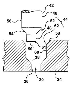
are typically provided in either the valve pin or the alignment means. These
slots create the potential for weld lines to appear in the molded product, as
a
result of the melt flow in the nozzle melt channel separating to pass around
the guide means, and subsequently reuniting downstream from the guide
means. Furthermore, the presence of such guide means in the nozzle melt
channel typically renders more difficult a cleanout of the nozzle melt
channel,
hampering for example the changeover of a machine to run a new melt.
[0006] Other solutions have provided an offset nozzle melt channel
which has a main portion that is offset from the center of the nozzle, and a
lowermost portion that is aligned with the gate. The valve pin passes through
the nozzle body and extends only into the lowermost portion of the nozzle
melt channel. In this way, the valve pin is captured along a substantial
portion
of its length, which makes it less susceptible to misalignment. However,
because a substantial portion of the nozzle melt channel is offset from the
center of the nozzle, the heat distributed to the melt flowing therethrough is
uneven, which can cause difficulties in controlling melt temperature.
Reference is made to US Patent Nos. 5,834,041 (Sekine et al) and 5,895,669
(Seres, Jr et al), which disclose embodiments of this genre of proposed
solution.
[0007] Other problems also exist, which originate from the manufacture
of the nozzles themselves instead from the properties of the melt flow.
Manufacturing errors may exist in the nozzles, which can introduce a
misalignment between the valve pin and the gate that is 'built-in'. The guide
means that are described above, which are built into the nozzle itself, do
nothing to correct this particular cause of misalignment.
CA 02492701 2005-O1-14
WO 2004/012923 PCT/CA2003/001154
-3-
[0008] Another issue relating to the valve pin has to do with the heat
transfer characteristics of the nozzle and the mold plate. Typically, a space.
exists between the downstream end of a nozzle and the gate of the mold
plate. The space is defined in part by the mold plate and in part by
components of the nozzle. The space typically fills with melt at the beginning
of an injection molding campaign. In some configurations of nozzle and mold
plate, the melt in the space solidifies as a result of the combined effects of
cooling from the mold plate, and insufficient heat transfer from the nozzle
components. In some circumstances the solidified melt in the space can
extend into the path taken by the valve pin towards the gate in the mold
plate.
Thus, in those circumstances, during movement of the valve pin towards the
gate, the valve pin contacts the solidified melt in the space. The contact
with
the solidified melt can push the leading edge of the valve pin out of
alignment
with the gate. Furthermore, the solidified melt can cause wear on the leading
edge of the valve pin, particularly if the melt is a glass-filled plastic or
is some
other abrasive material. Thus, it is possible for the valve pin to incur wear
on
its leading edge and sealing surfaces even when it is in perfect alignment,
depending on the thermal characteristics of the molding operation and the
material being injected.
[0009] Thus, a need exists for an injection molding apparatus that
provides improved guiding of the valve pin towards the gate.
SUMMARY OF THE INVENTION
[0010] In a first aspect, the invention is directed to an injection molding
apparatus comprising a manifold, a nozzle, a mold block, a valve pin, a first
guidance and alignment structure, and a second guidance and alignment
structure. The manifold has an inlet for receiving melt from a melt source.
The
manifold defines a runner that is downstream from the inlet and upstream
from a manifold outlet. The nozzle defines a nozzle melt channel. The nozzle
melt channel is downstream from the manifold outlet. The nozzle includes a
nozzle body, a nozzle tip, a sealed piece, and a heater thermally connected to
the nozzle body for heating melt in the nozzle melt channel. The nozzle tip
CA 02492701 2005-O1-14
WO 2004/012923 PCT/CA2003/001154
-4-
and the seal piece are connected with respect to the nozzle body. The nozzle
tip defines a portion of the nozzle melt channel. The thermal conductivity of
the nozzle tip is higher than the thermal conductivity of the nozzle body. The
thermal conductivity of the seal piece is lower than the thermal conductivity
of
the nozzle body. The mold block defines a mold cavity. The mold block
defines a gate into the mold cavity. The gate is downstream from the nozzle
melt channel. The gate includes a gate sealing surface. The mold block has at
least one cooling channel therein for conveying a coolant therethrough for
cooling the mold cavity. The mold block and the seal piece engage each other
to inhibit melt leakage therebetween. A chamber is defined between the mold
block, the nozzle tip, and the seal piece. The chamber is positioned
downstream from the nozzle melt passage and upstream from the gate. The
nozzle tip has sufficient surface area in the chamber to maintain melt in the
chamber in a substantially molten state. The valve pin is movable into and out
of the gate to control melt flow through the gate. The valve pin has a bottom
end. The valve pin has a valve pin sealing surface proximate the bottom end.
The valve pin sealing surface is engageable with the gate sealing surface to
inhibit melt flow into the mold cavity. The first guidance and alignment
structure is connected to the valve pin. The first guidance and alignment
structure includes a first guide surface and first alignment surface. The
first
guide surface has a cross-sectional diameter that decreases gradually in a
downstream direction. The first alignment surface is generally cylindrical.
The
first guide surface is positioned immediately downstream from the first
alignment surface. The second guidance and alignment structure is
connected to the mold block upstream from the gate. The second guidance
and alignment structure includes a second guide surface and a second
alignment surface. The second guide surface has a diameter that decreases
gradually in a downstream direction. The second alignment surface is
generally cylindrical. The second guide surface is positioned immediately
upstream from the second alignment surface. The second guide surface is
positioned to engage the first guide surface to slide the valve pin into
alignment with the gate when the valve pin is misaligned with the gate during
movement of the valve pin towards the gate. The second guide surface is
CA 02492701 2005-O1-14
WO 2004/012923 PCT/CA2003/001154
-5-
positioned to complete alignment of the valve pin with the gate prior to
contact
between the valve pin and the gate. The second alignment surface is
positioned to engage the first alignment surface to maintain the valve pin in
alignment with the gate during movement of the valve pin towards the gate.
[0011] In a second aspect, the invention is directed to an injection
molding apparatus, comprising a nozzle body, a valve pin, a nozzle tip, a seal
piece, and a mold gate insert. The nozzle body has a melt channel and is
made of a first material. The valve pin is at least partially positioned in
the
melt channel. The valve pin has a first guidance and alignment structure
thereon. The nozzle tip is connected to the nozzle body. The seal piece is
connected to the nozzle body. The mold gate insert has a gate. The mold gate
insert is in contact with the seal piece. The nozzle tip is made of a second
material having a higher thermal conductivity than the first material. The
seal
piece is made of a third material having a lower thermal conductivity than the
first material. The mold gate insert is made of a fourth material having a
higher thermal conductivity than the third material. The mold gate insert
includes a second guidance and alignment structure thereon that contacts the
first guidance and alignment structure before the valve pin contacts the gate.
[0012] In a third aspect, the invention is directed to a method of guiding
a valve pin for an injection molding apparatus into engagement with a gate of
said molding apparatus comprising:
[0013] providing a first guide surface on said valve pin adjacent to but
upstream from the sealing surface of said pin and a second guide surface on
said molding apparatus adjacent to but upstream from said gate;
[0014] providing a first alignment surface on said valve pin adjacent to
but upstream from the sealing surface of said pin and a second alignment
surface on said molding apparatus adjacent to but upstream from said gate;
and
[0015] guiding said valve pin as said pin moves downstream towards
said gate by interaction of said first and second guide surfaces and
interaction
of said first and second alignment surfaces before said pin closes said gate.
CA 02492701 2005-O1-14
WO 2004/012923 PCT/CA2003/001154
-6-
DESCRIPTION OF THE DRAWINGS
[0016] For a better understanding of the present invention and to show
more clearly how it may be carried into effect, reference will now be made by
way of example to the accompanying drawings, in which:
[0017] Figure 1 is a sectional view of an injection molding apparatus of
the prior art;
[0018] Figures 2a, 2b, 2c and 2d are magnified sectional side views
showing the operation of a valve pin and mold plate of the prior art;
[0019] Figure 3 is a sectional view of an injection molding apparatus
having a plurality of valve pin guidance and alignment systems in accordance
with a first embodiment of the present invention;
[0020] Figures 4a, 4b, 4c and 4d are magnified sectional side views of
the valve pin guidance and alignment system shown in Figure 3;
[0021] Figure 5 is a magnified sectional side view of a valve pin
guidance and alignment system in accordance with an alternative
embodiment of the present invention;
[0022] Figure 6 is a sectional side view of a portion of the injection
molding apparatus shown in Figure 3, including a misaligned valve pin and
the valve pin guidance and alignment system shown in Figures 4a-4d,
showing the valve pin in an open position with respect to a gate into a mold
cavity;
[0023] Figure 7 is a sectional side view of the injection molding
apparatus portion shown in Figure 6 illustrating first contact by the valve
pin
with a portion of the guidance and alignment system;
[0024] Figure 8 is a sectional side view of the injection molding
apparatus portion shown in Figure 6, illustrating the valve pin in a closed
position with respect to the gate;
CA 02492701 2005-O1-14
WO 2004/012923 PCT/CA2003/001154
-7-
[0025] Figure 9 is a sectional side view of a portion of the injection
molding apparatus, showing an optional relief channel that may be included in
the valve pin guidance and alignment system;
[0026] Figure 10 is a sectional side view of a portion of an injection
molding apparatus showing a misaligned valve pin and a valve pin guidance
and alignment system in accordance with another alternative embodiment of
the present invention, whereby the valve pin is in an open position with
respect to a gate into a mold cavity;
[0027] Figure 11 is a sectional side view of the injection molding
apparatus portion shown in Figure 10, illustrating first contact between the
valve pin and a portion of the valve pin guidance and alignment system;
[0028] Figure 12 is a sectional side view of the injection molding
apparatus portion shown in Figure 10, illustrating when the valve pin first
contacts another portion of the valve pin guidance and alignment system;
[0029] Figure 13 is a sectional side view of the injection molding
apparatus portion shown in Figure 10, illustrating the valve pin in a closed
position with respect to the gate;
[0030] Figure 14 is a sectional side view of a portion of an injection
molding apparatus showing a variant of the nozzle shown in Figures 6, 7 and
8;
[0031] Figure 15 is a sectional side view of a portion of an injection
molding apparatus showing another variant of the nozzle shown in Figures 6,
7 and 8;
(0032] Figure 16 is a sectional side view of a portion of an injection
molding apparatus showing yet another variant of the nozzle shown in Figures
6, 7 and 8;
[0033] Figure 17 is a magnified sectional view through section 17-17 of
Figure 4d;
(0034] Figure 18 is a magnified sectional view through section 18-18 of
Figure 4d;
CA 02492701 2005-O1-14
WO 2004/012923 PCT/CA2003/001154
_$_
[0035] Figures 19a and 19b are magnified side views of a variant of a
portion of a guidance and alignment structure shown in Figures 4a-4d; and
[0036] Figure 20 is a sectional side view of a portion of an injection
molding apparatus showing yet another variant of the nozzle shown in Figures
6, 7 and 8.
DESCRIPTION OF THE PREFERRED EMBODIMENT
[0037] Reference is made to Figure 1, which shows an injection
molding apparatus 1010 of the prior art. The injection molding apparatus
1010 includes one or more runners 1012,,that transfer melt from an inlet 1014
to one or more nozzles 1016. The runners 1012 are defined within one or
more molding apparatus plates, such as, for example, a manifold 1018. The
inlet 1014 is adapted to be fluidly connected to a melt source (not shown).
[0038] The nozzles 1016 transfer melt from the runners 1012 through
one or more gates 1020 and into one or more mold cavities 1022 defined in a
mold plate 1024. A heater 1025 may heat each nozzle 1016. Each nozzle
1016 defines a nozzle melt channel 1026 which is in fluid communication with
a runner 1012 and thus, with the melt source.
[0039] A valve pin 1028 is movable within each nozzle melt channel
1026 to open and close one of the gates 1020, permitting or restricting the
flow of melt into the mold cavity 1022. The configuration of the end portion
of
the valve pin 1028 and the gate 1020 and their engagement are shown in
more detail in Figures 2a, 2b, 2c and 2d. The valve pin 1028 typically
includes a generally cylindrical body 1030, a cylindrical sealing surface
1031,
which is typically on the endmost portion of the body 1030, and an end face
1032. The edge between the end face 1032 and the sealing surface 1031 is
shown at 1034 and is typically chamfered to facilitate the introduction of the
valve pin 1028 into the gate 1020.
[0040] Due to the fact that the end face 1032 and chamfered edge
1034 will ultimately make up a portion of the surface of the mold cavity 1022,
there may be design restrictions on the angle of the chamfered edge 1034.
For example, the chamfered edge 1034 may be limited to having a relatively
CA 02492701 2005-O1-14
WO 2004/012923 PCT/CA2003/001154
_g_
shallow angle with respect to the end face 1032 so as to provide a certain
shape in the molded part.
[0041] The gate 1020 typically includes a cylindrical sealing surface
1036 adjacent the mold cavity 1022, and also includes a lead-in surface 1038
that is chamfered. The sealing surface 1036 receives and cooperates with
the sealing surface 1031 of the valve pin 1028 to seal the gate 1020 against
melt flow into the mold cavity 1022. The lead-in surface 1038 cooperates with
the chamfered edge 1034 on the valve pin 1028 to facilitate the introduction
of
the valve pin 1028 into the gate 1020.
[0042] The movement of the valve pin 1028 will now be described. In
Figure 2a, the valve pin 1028 is shown spaced from the gate 1020. The valve
pin 1028 may be misaligned with the gate 1020 to any degree. When the
valve pin 1028 is moved to close the gate 1020, if there is any misalignment
of the valve pin 1028 and gate 1020, the valve pin 1028 first contacts the
gate
1020 in the manner shown in Figure 2b. The first contact is made by the
chamfered edge 1034 and the lead-in surface 1038. As the valve pin 1028
moves forward to close the gate 1020, the chamfered edge 1034 slides off the
lead-in surface 1038 thereby guiding the valve pin 1028 into alignment with
the gate 1020. The valve pin 1028 then moves forwardly in the sealing
surface 1036 of the gate 1020, as shown in Figure 2c until arriving at the
'closed' position, as shown in Figure 2d. It will be appreciated that the
'closed'
position of the valve pin 1028 need not be as shown in Figure 2d. After a
number of molding cycles, the repeated contact between the valve pin 1028
and the inlet surface 1036 of the gate 1020 can eventually result in one or
both of the sealing surface 1031 of the valve pin 1028 and the sealing surface
1036 of the gate 1020 being scored, worn away or otherwise damaged.
[0043] The portions of the valve pin 1028 and the gate 1020 that can
be damaged are shown at 1039a and 1039b respectively. This damage can
result in melt leaking past the gate 1020 after the gate 1020 is closed, and
can also result in blemishes on the molded part. Thus, depending on the
needs of the molding operation, the valve pin 1028 and the gate 1020 may
require repair or replacement. It will be noted that the scoring or damage
CA 02492701 2005-O1-14
WO 2004/012923 PCT/CA2003/001154
-10-
shown at 1039a and 1039b can occur almost immediately, depending on the
nature of the molding operation, and thus poor quality parts can result
virtually
immediately. This problem is exacerbated if the angle of the chamfered edge
1034 on the valve pin 1028 is shallow, because the contact forces between
the valve pin 1028 and the lead-in surface 1038 can further promote wear,
scoring or other damage.
[0044] Reference is made to Figure 3, which shows an injection
molding apparatus 40, in accordance with a first embodiment of the present
invention. The injection molding apparatus 40 may be any suitable type of
injection molding apparatus, and may be generally similar to the injection
molding apparatus 1010, except that the injection molding apparatus 40
includes a valve pin 42 and a guidance and alignment system 44. The valve
pin guidance and alignment system 44 prolongs the life of the valve pin 42
and gate 20 by reducing or eliminating contact between the valve pin 42 and
gate 20 during closure of the gate 20, and by reducing wear on the valve pin
42 as a result of contact with solidified melt, which can be abrasive.
[0045] The injection molding apparatus 40 includes one or more
runners 12, that transfer melt from an inlet 14 to one or more nozzles 16. The
runners 12 are defined within one or more molding apparatus plates, such as,
for example, a manifold 18. The inlet 14 is adapted to be fluidly connected to
a melt source (not shown).
[0046] The nozzles 16 transfer melt from the runners 12 through one or
more gates 20 and into one or more mold cavities 22 defined in a mold block
24. A plurality of cooling channels 24a are shown in the mold block 24. The
mold block may be made from any suitably thermally conductive material,
such as mold steel.
[0047] A heater 25 may heat each nozzle 16, and a thermocouple 25a
may be used to sense the temperature of the nozzle 16. Each nozzle 16
defines a nozzle melt channel 26 which is in fluid communication with one of
the runners 12 and thus, with the melt source.
CA 02492701 2005-O1-14
WO 2004/012923 PCT/CA2003/001154
-11 -
[0048] One of the valve pins 42 is movable within each nozzle melt
channel 26 to open and close one of the gates 20, permitting or restricting
the
flow of melt into one of the mold cavities 22.
[0049] Reference is made to Figures 4a, 4b, 4c and 4d, which show the
configuration of the end portion of valve pin 42, the valve pin guidance and
alignment system 44 and the gate 20. The valve pin 42 includes a body 46, a
sealing surface 48, an end face 50 and a first guidance and alignment
structure 52. The body 46 may have any suitable shape, such as generally
cylindrical. The sealing surface 48 may be similar to the sealing surface 1031
on the valve pin 1028 in Figures 2a - 2d, and cooperates with the sealing
surface 36 of the gate 20 to close the gate 20.
[0050] The first guidance and alignment structure 52 is positioned
between the body 46 and the sealing surface 48, and includes a first tapered
guide surface 54 and a first alignment surface 56. The first tapered guide
surface 54 and first alignment surface 56 cooperate with a second tapered
guide surface 58 and a second alignment surface 60 on a second guidance
and alignment structure 62, to bring the valve pin 42 into alignment with the
gate 20.
[0051] As the valve pin 42 moves from the position shown in Figure 4a
towards the gate 20, if there is any misalignment between the valve pin 42
and the gate 20, the first contact made occurs between the first and second
guide surfaces 54 and 58, as shown in Figure 4b. The first and second guide
surfaces 54 and 58 may be provided with any selected angle of taper. Thus,
the taper angles, which are shown at 01 and 02 respectively, can be selected
to reduce the risk of scoring or otherwise damaging one or both guide
surfaces 54 and 58 upon first contact or upon any subsequent sliding contact.
[0052] It will be noted that the guide surfaces 54 and 58 and the
alignment surfaces 56 and 60 on the first and second structures 52 and 62
have a larger diameter than the surfaces 1036, 1038, 1034 and 1031 on the
gate 1020 and valve pin 1028 of Figures 2a-2d. By having the contact and
sliding occur on these larger diameter surfaces 54, 58, 56 and 60, the first
and
CA 02492701 2005-O1-14
WO 2004/012923 PCT/CA2003/001154
-12-
second structures 52 and 62 are adapted to have a longer service life before
requiring repair or replacement, relative to the smaller diameter surfaces
1036, 1038, 1034 and 1031 of Figures 2a-2d.
[0053] One or both of the first and second guide surfaces 54 and 58
may be hardened by any suitable surface treatment means, to further reduce
the risk of scoring. One of the first and second guide surfaces 54 and 58 may
be selected to be harder than the other, so that the softer of the two may be
'sacrificed' during the repeated contacting and sliding that occurs during an
injection molding campaign. The surface 54 or 58 that is selected to be
sacrificed may be, for example, on the part that is the less expensive of the
two, the easier of the two or the less time consuming of the two to replace.
[0054] As the valve pin 42 is moved towards the gate 20, the first and
second guide surfaces 54 and 58 cooperate to bring the valve pin 42 into
alignment with the gate 20. Once the first guide surface 54 is moved past the
second guide surface 58, the first and second alignment surfaces 56 and 60
contact each other to maintain the valve pin 42 in alignment with the gate 20.
The valve pin 42 is then moved towards and into the gate 20, to close the
gate 20, as shown in Figure 4d.
[0055] The first and second alignment surfaces 56 and 60 may be
surface treated in a similar way to the first and second guide surfaces 54 and
58, and may also include one surface 56 or 60 that is selected to be
sacrificial.
[0056] It will be noted that, because the valve pin 42 is aligned with the
gate 20 before entering the gate 20, a chamfered edge is not required
between the end face 50 and the sealing portion 48. By not chamfering the
edge, it is possible to virtually eliminate any blemishes on the molded part,
by
moving the valve pin 42 into the gate 20 so that the end face 50 is flush with
the interior surface of the mold cavity 22.
[0057] Nonetheless, a chamfered edge may be included optionally, and
is shown at 61. The chamfered edge 61 may, however, have any suitable
CA 02492701 2005-O1-14
WO 2004/012923 PCT/CA2003/001154
-13-
shape as desired to meet the aesthetic requirements of the molded part, with
no effect on the ability of the valve pin 42 to enter and close the gate 20.
[0058] The portions of the components shown in Figures 4a - 4d, that
incur wear and damage are shown at 64a and 64b, and are positioned away
from the sealing surfaces 48 and 36. Thus, by incorporating the first and
second guidance and alignment structures 52 and 62, the service life of the
valve pin 42 may be extended beyond the service life of the valve pin 28.
Furthermore, since damage from misalignment is reduced or eliminated,
blemishes that occur on the molded parts as a result of the damage are
reduced or eliminated.
[0059] Together, the first and second guidance and alignment
structures 52 and 62 make up the valve pin guidance and alignment system
44. It has been shown for the first and second guidance and alignment
structures 52 and 62 to be integrally incorporated into the valve pin 42 and
the
mold block 24, the structures 52 and 62 may be made as separate pieces,
which may be joined to the valve pin 42 and mold block 24 by any suitable
means. For example, referring to Figure 5, the first structure 52 may be made
as a ring that includes a threaded portion 66, which mates with a
corresponding threaded portion 68 on the valve pin 42. By making the
structure 52 as a separate piece that is removable from the valve pin 42, the
structure 52 may more easily be made from any suitable material having any
desired mechanical properties. The structure 52 may be made to be hard and
to resist wear, or alternatively, the structure 52 may be made to be soft, if,
for
example, the structure 52 is selected to be sacrificial, as described above.
The first structure may also include a tool engaging surface 69 for
installation
and removal of the first structure 52 from the valve pin 42.
[0060] In a similar fashion to the structure 52, the structure 62 may be
made as a separate piece, such as a ring and may be made to be removably
connectable to the mold block 24 by means of mating threaded portions 70
and 72 on the structure 62 and the mold block 24 respectively. The second
structure may also include a raised tool engaging surface 73 for installation
and removal of the second structure 62 from the mold block 24. As a
CA 02492701 2005-O1-14
WO 2004/012923 PCT/CA2003/001154
-14-
separate, removably attachable piece, the mechanical properties of the
second structure 62 may be selected as desired.
[0061] Referring to all embodiments, the second structure 62 must be
positioned far enough away from the gate 20, so that the valve pin 42 is
aligned by the cooperation of the first and second guide surfaces 54 and 58
before any portion of the valve pin 42 contacts the gate 20. With deference to
the condition above, it is however advantageous for the second structure 62
to be positioned as close as possible to the gate 20, to reduce the risk of
the
end of the valve pin 42 becoming misaligned again after being aligned by the
second structure 62. Such misalignment can occur again, for example, due to
non-homogeneity in the melt downstream from the second structure 62.
[0062] Reference is made to Figure 17, which shows a magnified
sectional view of the first and second alignment surfaces 56 and 60. In Figure
17, the valve pin 42 is shown as being centered perfectly within the
cylindrical
alignment surface 60. The diameter of the first alignment surface is shown as
D1. The diameter of the second alignment surface 60 is shown at D2.
[0063] Reference is made to Figure 18, which shows a magnified
sectional view of the valve pin sealing surface 48 and the gate sealing
surface
36. In Figure 18, the valve pin 42 is shown as being centered perfectly within
the cylindrical gate sealing surface 36. The diameter of the valve pin sealing
surface 48 is shown as D3. The diameter of the gate sealing surface 36 is
shown as D4.
[0064] Referring to Figures 17 and 18 together, it is preferable that the
valve pin 42 and the gate 20 and the second guidance and alignment
structure 62 are manufactured so that the difference between D1 and D2 is
less than the difference between D3 and D4. To achieve this, the tolerances
on the first and second alignment surfaces 56 and 60 may need to be tighter
than the tolerances on the valve pin sealing surface 48 and the gate sealing
surface 36. By providing a smaller diameter difference on the first and second
alignment surfaces 56 and 60 than on the sealing surfaces 48 and 36, the
valve pin 42 is ensured to be aligned for a collision-free ehtry with the gate
20.
CA 02492701 2005-O1-14
WO 2004/012923 PCT/CA2003/001154
-15-
Even if the valve pin 42 were so far out of alignment that the alignment
surfaces 56 and 60 were in contact with each other, the end face 50 (see
Figure 4d) would be assured of entering collision-free into the gate 20. In
effect, the diameter difference between D1 and D2 (see Figure 17) at least in
part limits the amount that the valve pin 42 can be off from being in perfect
alignment with the gate 20 (see Figure 4c).
[0065] Reference is made to Figure 6, which shows a portion of the
injection molding apparatus 40 that includes an optional gate insert 74 that
is
positioned in the mold block 24. Throughout the description of embodiment of
the invention, components that are similar and have similar functions are
provided with the same reference numbers. In this embodiment, the second
guidance and alignment structure 62 and the gate 20 are included in the gate
insert 74, instead of being directly included in the mold block 24. The gate
insert 74 may be made from any suitably thermally conductive material, such
as mold steel. The gate insert 74 is thermally conductive to assist in cooling
melt contained in the mold cavity 22. Preferably, the gate insert 74 has a
thermal conductivity that is higher than that of the seal piece 16c.
[0066] In Figure 6, the nozzle 16 is shown as being made up of several
subcomponents. The nozzle 16 includes a nozzle body 16a, a nozzle tip 16b
and a seal piece 16c. The nozzle body 16a may have the heater 25
embedded therein in a helical groove. The nozzle body 16a has a first portion
26a of the melt channel 26 therein. The nozzle body 16a may be made from
any suitable thermally conductive material, such as steel.
(0067] The nozzle tip 16b connects to the nozzle body 16a and has a
second portion 26b of the melt passage 26 therein. The nozzle tip 26b may
be made from a thermally conductive material such as steel, Beryllium-
Copper, Beryllium-free copper such as Ampco 940T"", Tungsten Carbide, TZM
(Titanium/Zirconium carbide), Aluminum or Aluminum-based alloys, InconelT"",
Molybdenum or suitable Molybdenum alloys, H13, mold steel or AerMet 100T""
or any other suitable material. By making the nozzle tip 16b as a separate
component from the nozzle body 16a, the nozzle tip 16b may be made from a
different material. For example, the nozzle tip 16b may be made from a
CA 02492701 2005-O1-14
WO 2004/012923 PCT/CA2003/001154
-16-
material that has a higher thermal conductivity than that of the nozzle body
16a. Alternatively, or in addition, the nozzle tip 16b may be made from a
material that is more wear resistant than that of the nozzle body 16a.
[0068] The nozzle tip 16b may be removably connected to the nozzle
body 16a. The removable connection may be made by any suitable means.
For example, the nozzle tip 16b may seat within a bore 75 in the nozzle body
16a, and may be retained in place by the seal piece 16c. Because the nozzle
tip 16b is removable from the nozzle body 16a, it may be replaced when it is
worn, without necessitating the replacement of the entire nozzle body 16a.
[0069] The seal piece 16c may connect to the nozzle body 16a by
means of a threaded connection between a pair of mating threaded surfaces
76a and 76b on the nozzle body 16a and the seal piece 16c respectively. The
seal piece 16c may contact the mold block 24 and for a seal therewith against
melt leakage. Furthermore, the seal piece 16c may align the downstream end
of the nozzle 16 with respect to the gate 20.
[0070] The seal piece 16c may be made from a less thermally
conductive material than that of the nozzle body 16a. For example, the seal
piece 16c may be made from titanium, H13, stainless steel, chrome steel or
other suitable materials.
[0071] The seal piece 16c may include an integral tool engagement
portion 73 that facilitate gripping of the seal piece 16c by a tool during
removal
or installation of the seal piece 16c.
[0072] In alternative embodiments, the nozzle body 16a, the nozzle tip
16b and the seal piece 16c may connect together in any way shown in US
Patent No. 5,299,928, and 5,421,716, both of which are hereby incorporated
by reference. In addition, reference is made to these two patents for suitable
materials of construction for the nozzle body 16a, the nozzle tip 16b and the
seal piece 16c.
[0073] A chamber 77 may be defined between the seal piece 16c, the
nozzle tip 16b and the mold block 24. The chamber 77 is filled with melt
during an injection molding operation. Depending on the composition of the
CA 02492701 2005-O1-14
WO 2004/012923 PCT/CA2003/001154
-17-
melt, it may be advantageous for the melt in the chamber 77 to be maintained
in a molten state throughout the injection cycle. By preventing the melt in
the
chamber from solidifying, the valve pin 42 is ensured to pass only through
molten melt instead of solidified melt when it moves through the chamber 77
on its way to or from the gate 20. Passing the valve pin 42 through molten
melt subjects the valve pin 42 to less wear than passing the valve pin 42
through solidified melt. Furthermore, molten melt has a reduced likelihood of
pushing the valve pin out of alignment than solidified melt.
[0074] To ensure that the melt in the chamber 77 is molten when the
valve pin 42 moves therethrough, a sufficient surface area of the nozzle tip
16b is present in the chamber 77 to heat the melt therein, and to counteract
any cooling effects that may sustained from the mold block 24.
[0075] In an alternative embodiment that it not shown, the nozzle tip
and the seal piece may each connect to the nozzle body by means of
threaded connections. It is also alternatively possible for the seal piece to
connect to the nozzle tip, and for the nozzle tip to connect to the nozzle
body
by some suitable means, such as a threaded connection.
[0076] In another embodiment that is not shown, the nozzle tip and the
seal piece may both be press-fit into or onto the nozzle body. The press-fit
may be suitably tight to maintain the assembly in connection even under
injection pressures. Alternatively, the press-fit may be less tight, to
facilitate
removal when desired, in which case, the components may be held in place
by pinning between the mold block and the nozzle.
. [0077] In the embodiment shown in Figure 6, the valve pin 42 includes
an optional relief channel 78 that extends longitudinally along a portion of
the
body 46. The function of the relief channel 78 is explained further below.
[0078] In the position shown in Figure 6, the valve pin 42 is in the open
position and is spaced from the gate 20. Referring to Figure 7, as the valve
pin 42 is moved towards the gate 20, if the valve pin 42 is misaligned with
respect to the gate 20, the first contact made by the valve pin 42 is between
the first guide surface 54 and the second guide surface 58. The valve pin 42
CA 02492701 2005-O1-14
WO 2004/012923 PCT/CA2003/001154
-18-
is guided by the cooperation between the first and second guide surfaces 54
and 58, into alignment, and the alignment is maintained by the first and
second alignment surfaces 56 and 60, until the valve pin 42 closes the gate
20, as shown in Figure 8.
[0079] As the valve pin 42 approaches the position shown in Figure 8,
the relief channel 78 that is included in the first alignment surface 56
provides
a path for the melt that is displaced by the end of the valve pin 42 itself as
it
moves towards closing the gate 20.
[0080] Referring to Figure 9, it is alternatively possible for the second
alignment surface 60 to include a relief channel 79 instead of the relief
channel 78 on the valve pin 42.
[0081] An alternative construction for the nozzle body 16a, the nozzle
tip 16b and the seal piece 16c is shown in Figure 9. The bore 75 in the nozzle
body 16a shown in Figure 9 is threaded, for mating with a threaded outer
surface of the nozzle tip 16b. The threaded tip 16b may thus connect directly
to the nozzle body 16a. The seal piece 16c may mount in any suitable way to
the nozzle tip 16b.
[0082] Reference is made to Figure 10, which shows the valve pin
guidance and alignment system 44, further comprising optional third and
fourth guidance and alignment structures 80 and 87, which cooperate to
further align the valve pin 42 with respect to the gate 20.
[0083] The third guidance and alignment structure 80 positioned on the
valve body 46, upstream from the first structure 52. The term upstream is
used in relation to the direction of the melt flow through the nozzle 16. The
third structure 80 may be similar to the first structure 52 except that the
third
structure 80 has a generally larger diameter than the first structure 52. The
third structure 80 includes a third guide surface 84 and a third alignment
surface 86.
[0084] The fourth structure 87 may be similar to the second structure
62 and may include a fourth guide surface 88 and a fourth alignment surface
CA 02492701 2005-O1-14
WO 2004/012923 PCT/CA2003/001154
-19-
90. The fourth structure 87 may be positioned anywhere suitable, such as on
the nozzle tip 16b.
[0085] It is particularly preferable in the embodiment shown in Figure
10, for the nozzle 16 and more particularly the nozzle tip 16b to be aligned
with the gate 20 so that the third and fourth structures 80 and 87 cooperate
with the first and second structures 52 and 62 to provide improved alignment
of the valve pin 42.
[0086] The third and fourth structures 80 and 87 may be integrally
included on the valve pin 42 and the nozzle tip 16b, as shown in Figure 10, or
one or both may be separate from the valve pin 42 and the nozzle tip 16b,
and may be removably attached thereto.
[0087] As shown in Figure 11, if the valve pin 42 is misaligned, the first
contact by the valve pin 42 occurs on the guide surface 88 of the fourth
structure 87. The guide surface 88 may be angled with a relatively slow taper,
to reduce pressure losses in the melt flow through the nozzle tip 16b. Care
must be taken to ensure that the third and fourth guide surfaces 84 and 88
cooperate to ensure that other surfaces of the valve pin 42 such as the
sealing surface 48, do not contact the nozzle tip 16b.
[0088] After the valve pin 42 is aligned by the cooperation of the third
and fourth alignment surfaces 86 and 90, the valve pin 42 next contacts the
first and second structures 52 and 62, as shown in Figure 12. The alignment
surfaces 56 and 60 cooperate with the alignment surfaces 86 and 90 so that
that the valve pin 42 enters the gate 20 relatively straight and not at an
angle
with respect to the axis of the gate 20, as shown in Figure 13. This further
reduces the risk of scoring or otherwise damaging the sealing surfaces 36 and
48 on the valve pin 42 and the gate 20.
[0089] Reference is made to Figure 14, which shows a variant of the
nozzle 16. In this variant, the nozzle tip 16b is not threaded, and seats in
the
bore 75 in the nozzle body 16a. The nozzle body 16a has a threaded surface
76a that is externally threaded. The seal piece 16c has an internally threaded
surface 76b that mates with the threaded surface 76a.
CA 02492701 2005-O1-14
WO 2004/012923 PCT/CA2003/001154
-20-
[0090] The seal piece 76c holds the nozzle tip 16a in place in the bore
75, but does not have direct contact with the nozzle tip 16a. Instead, there
is
provided a second seal piece 16d between the seal piece 16c and the nozzle
tip 16b.
[0091] The presence of the second seal piece 16d maintains an air gap
94 between the seal piece 16c and the nozzle tip 16b. Because the nozzle tip
16b and the seal piece 16c do not directly contact one another at any point,
the overall heat transfer between them is reduced, relative to a configuration
where they directly contact each other.
[0092] Furthermore, the air gap 94 further reduces the heat transfer
between the nozzle tip 16b and the seal piece 16c. Because air has a
relatively lower thermal conductivity than melt, the air gap 94 insulates
better
against heat transfer between the tip 16b and the seal piece 16b, than if the
air gap 94 were filled with melt. By reducing the heat losses out of the
nozzle
tip 16a, the melt therein can more easily be maintained at a controlled
temperature prior to injection into the mold cavity 22.
[0093] The second seal piece 16d may be an o-ring 96 that is
positioned in a first groove in the nozzle tip 16b and a second groove in the
seal piece 16c. It is alternatively possible for one of the nozzle tip 16b and
the
seal piece 16c to contain a sufficiently deep groove to capture the o-ring 96
and the other of the components 16b and 16c to not have a groove at all.
[0094] The second seal piece 16d may be made from a material that is
suitable for sealing against melt leakage. For example, in the form of the o-
ring 72, suitable materials include stainless steels, such as Inconel. The
second seal piece 16d may also be made from a material that has a thermal
conductivity that is lower than that of the tip 16b, to reduce the heat loss
from
the tip 16b to the seal piece 16c. More preferably, the second seal piece 16d
has a thermal conductivity that is lower than that of the nozzle body 16a.
Even more preferably the second seal piece 16d has a thermal conductivity
that is lower than that of the seal piece 16c.
CA 02492701 2005-O1-14
WO 2004/012923 PCT/CA2003/001154
-21 -
[0095] The specific cross-sectional shape of the second seal piece 16d
has been shown as being generally circular, however, other cross-sectional
shapes may be used.
[0096] The guidance and alignment surfaces 54, 56, 58 and 60 and the
sealing surfaces 36 and 48 operate in a manner similar to that described with
respect to the embodiment of Figures 6-8.
[0097] Reference is made to Figure 15, which shows another variant of
the nozzle 16 that is similar to the variant shown in Figure 14. In the
variant of
Figure 15, however, the internally threaded surface 76b of the seal piece 16c
mates with an externally threaded surface 76c on an insulator piece 16e. The
insulator piece 16e may also have an internally threaded surface 76d that
mates with the externally threaded surface 76a of the nozzle body 16a.
[0098] The optional insulator piece 16e is attached to the nozzle body
82 and receives the tip surrounding piece 86. The insulator piece 16e may be
made from a material having a relatively lower thermal conductivity than that
of the seal piece 16c, to reduce the overall thermal conductivity of the path
from the nozzle body 16a, through the insulator piece 16e, in turn through the
seal piece 16c, and into the mold component 24.
[0099] By having the insulator piece 16e between the seal piece 16c
and the nozzle body 16a, the seal piece 16c may be made from a material
having any desired wear resistance, with less regard to whether it has a
relatively high or low thermal conductivity relative to that of the nozzle
body
16a.
[00100] The guidance and alignment surfaces 54, 56, 58 and 60 and the
sealing surfaces 36 and 48 operate in a manner similar to that described with
respect to the embodiment of Figures 6-8.
[00101] Reference is made to Figure 16, which shows yet another
variant of the nozzle 16 that is similar to the variant shown in Figure 14. In
the
variant of Figure 16, however, the bore 75 in the nozzle body 16a has a
threaded portion 76e that mates with a corresponding threaded surface 76f on
the nozzle tip 16b. The seal piece 16d in this embodiment also has the
CA 02492701 2005-O1-14
WO 2004/012923 PCT/CA2003/001154
-22-
internally threaded surface 76b that mates with the externally threaded
surface 76a of the nozzle body 16a.
[00102] The guidance and alignment surfaces 54, 56, 58 and 60 and the
sealing surfaces 36 and 48 operate in a manner similar to that described with
respect to the embodiment of Figures 6-8.
[00103] A particular example of an injection molding apparatus is shown
in the Figures. It will be appreciated that the injection molding apparatus
may
be any suitable type of injection molding apparatus. Furthermore, the
injection molding apparatus may have as little as one runner, or may have
more runners, and may have as little as one mold cavity or may have more
mold cavities. Furthermore, each mold cavity may be provided with more
than one gate. Also, more than one material may be transferred
simultaneously through the injection molding apparatus and into each mold
cavity, for example, when making molded articles that have multiple layers of
different materials.
[00104] In the embodiments described above, the first and second guide
surfaces have been described as being frusto-conical, however, it will be
appreciated that other shapes of surface are suitable. For example, the first
and second guide surfaces may be arcuate in profile (see Figures 19a and
19b). As shown in Figure 19a, the first guide surface 54 may curve gradually
into the first alignment surface 56. The gradual curve eliminates the corner
edge that exists between the first guide surface 54 and the first alignment
surface 56 in the embodiments shown in Figures 3 - 16. The gradual curve
thus eliminates a potential source of damage to the valve pin and the second
guidance and alignment structure.
[00105] As shown in Figure 19b, the second guide surface 58 may
gradually curve into the second alignment surface 60, thereby eliminating a
corner edge that exists in the embodiments shown in Figures 3-16. The
gradual curve thus eliminates a potential source of damage. As a further
alternative, a gradual curve may be applied between the first surfaces 54 and
56 and the second surfaces 58 and 60.
CA 02492701 2005-O1-14
WO 2004/012923 PCT/CA2003/001154
- 23 -
[00106] In some embodiments described above, the second guidance
and alignment structure is integrally included in the mold block, while in
others
the second guidance and alignment structure is included in a separate gate
insert, in a separate piece that mounts removably from the mold block 24 and
is separate from the gate (see Figure 5 and 6). It is within the scope of the
invention for the mold block in any of the embodiments described above, to
optionally include any structure, which may be removable or fixedly mounted
therein, that could have the second guidance and alignment structure defined
therein, or to have the second guidance and alignment structure defined
integrally directly in the mold block. Referring to Figure 20, the gate 20
may,
for example, be defined in a gate insert 98 that is connected to both the
nozzle body 16a and the mold block 24. In the embodiment shown in Figure
20, the gate insert 98 replaces the seal piece provided in the embodiments in
Figures 3-16. In this embodiment, the second guide surface 58 and the
second alignment surface 60 are positioned upstream from the gaffe 20 in the
gate insert 98. The gate insert 98 is connected to the nozzle body 16a by
means of a threaded connection. The gate insert 98 may connect to an outer
surface of the nozzle body 16a, as shown in Figure 20. In any alternative
embodiment that is not shown, the gate insert may connect to an internal bore
in the nozzle body.
[00107] In the embodiments described, the nozzle included a nozzle
body and a nozzle tip that are thermally conductive and a seal piece that is
less thermally conductive, and that is connected directly to the nozzle body
and/or the nozzle tip. It is alternatively possible for the seal piece to be
connected to another component that attaches to the nozzle body or nozzle
tip. This other component may itself be made from a thermally conductive
material if desired since it is not in direct contact with the mold block 24.
[00108] While the above description constitutes the preferred
embodiments, it will be appreciated that the present invention is susceptible
to
modification and change without departing from the fair meaning of the
accompanying claims.