Note: Descriptions are shown in the official language in which they were submitted.
CA 02492713 2005-O1-14
WO 2004/063067 PCT/IT2004/000005
- 'I -
Reiwinding machine and method for the production of logs, With means to
control
the final diameter of the logs
Description
Technical field
The present invention relates to a rewinding machine and more specifically
to a surface rewinding machine, of the continuous type or of the start-stop
type. In
surface winding machines the web material is wound by maintaining the log in
rotation in the forming phase through frictional force transmitted by winding
members forming a winding cradle.
More specifically, the present invention relates to a rewinding machine of
the type comprising a winding cradle constituted by winding rollers and
specifically
comprising at least one roller with a moving axis that is maintained in
contact with
the log being formed and gradually moved away from.the axis of the log to
allow it
to increase in diameter.
The invention also relates to a method for producing logs of web material.
As shall become apparent hereunder, the invention can be applied both in
the forming of logs with central cores or central winding spindles and of logs
without central winding cores.
Background of the inverition
Surface rewinding machines are currently used to. produce logs of web
material, in particular, although not exclusively, paper such as tissue paper,
for
example toilet tissue, kitchen paper and the like. In,these machines the log
being
formed is made to rotate through the effect of winding members in peripheral
contact with the log. Typically, these winding members are rollers or, in some
cases, belts or combinations of rollers and belts. '
Surface winding machines may be of the contiriuous type, that is in which
the web material is fed continuously and at an essentially constant speed,
even
during the exchange phase. This is the phase during which the web material is
severed, the completed log is unloaded from the winding cradle and winding of
a
new log commences in the winding cradle. Surface winding machines can also be
of the start-stop or discontinuous type. In this type feed of the web material
is
interrupted during the exchange phase.
The logs formed in rewinding machines are subsequently .cut into rolls of a
smaller axial length and these are packaged, normally in multiple packages, to
be
CA 02492713 2005-O1-14
WO 2004/063067 PCT/IT2004/000005
SOId.
One of the critical aspects when forming logs is control of the diameter and
the quantity of wound material. In fact, in order to allow correct operation
of
packaging machines the logs, and therefore the rolls obtained from them, must
have more or less the same diameter, i.e. coming within a relatively narrow
range
of tolerance. Excessive variations in the diameter of logs causes problems and
blocking during subsequent packaging of the rolls.
Moreover, each roll must contain a minimum quantity of web material,
equivalent to the quantity declared on the packaging. If the quantity is below
the
one declared sellers and manufacturers could be reported for fraud. A quantity
above the nominal amount causes economic losses for the manufacturer.
Therefore! winding of logs must be controlled so that their external diameter
does not, differ significantly from the nominal value, obtained with a
predetermined
quantity of wound material or slightly above said predetermined. quantity.
While in the most advanced and more costly rewinding machines these
parameters are controlled accurately with sophisticated electronic systems, a
problem often occurs in less costly machines equipped with limited control
systems in that having set the length of the web material wound on each log,
the
external diameters of the various.. logs differ greatly. This depends on
variations in
thickness to which paper (especially.tissue paper) is subject by nature.
US-A-5267703 describes a rewinding machine with a winding roller with
moving axis associated with a member to control movement of the roller, to
ensure
that a diameter contained within a predetermined range of tolerance is
obtained,
with a pre-established quantity of wound web material. This machine is
efficient
and has a limited cost. Nonetheless it is still too sophisticated for some
types of
market also on account of the diameter control system used.
Objects and summary of the invention
The object of the present invention is to provide a rewinding machine that
allows logs with sufficiently uniform diameters (i.e. falling within a
restricted range
of variation) to be obtained without sophisticated control systems being
required.
Essentially, this and other objects and advantages, which shall become
apparent to those skilled in the art from reading the text hereunder, are
obtained
with a surface rewinding machine with a winding roller with moving axis,
associated with a pair of actuators that control movement of the roller.
According
CA 02492713 2005-O1-14
WO 2004/063067 PCT/IT2004/000005
_3_
to the invention, the two actuators are connected to each other. One of said
actuators controls movement of the winding roller axis during increase in the
log
being formed, and has a position (especially, for example, a stroke end
position of
a piston of a piston-cylinder actuator) that corresponds to the dimension of
the
final diameter of the log I~eing formed. The second actuator, on the other
hand, is
used~to impart movement to the winding roller with moving axis to move it away
from the completed log to allow unloading.
With an arrangement of this type during formation of the log in the winding
cradle the winding roller with moving axis is gradually lifted and moved away
from
the remaining members forming the winding cradle, for example a further pair
of
winding rollers. Gradual lifting is caused by the log being formed, which
increases
in diameter. Before the entire quantity of web material has been wound,
movement
of the winding roller with moving axis is stopped, the actuator controlling it
reaching its stroke end position. Winding of the final portion of web material
takes
place with increased pressure on the log, which can no longer increase in
diameter. This means that the final turns of-wound material are tighter and
more
compact. This does not cause particular drawbacks and, moreover, ensures that
the dimension of the diameter of the finished log comes within a relatively
limited
range of tolerance that will not cause problems during subsequent handling and
in
particular during final packaging of the rolls obtained from cutting the logs.
In some
cases the presence of a certain number of external turns wound more compactly
may even kie an advantage, as it protects the log from possible mechanical
strains. This is particularly true in the case of soft logs, which are wound
with
limited compactness.
The number of turns wound around the log after the roller with moving axis
stops depends on how the previous turns were wound. The slacker the previous
turns are, the greater the quantity of web material still to be wound after
the log
reaches its predetermined final diameter will be. The more compact winding,
performed before the gradual lifting movement of the winding roller with
moving
axis stops, is, the fewer the number of turns still to be wound around the log
in
conditions of greater winding pressure, and therefore with increased
compactness,
will be'.
As movement of the winding roller with moving axis is advantageously
stopped by bringing the first actuator to its stroke end, the subsequent
movement
CA 02492713 2005-O1-14
WO 2004/063067 PCT/IT2004/000005
-4-
in the same direction required to move the winding roller away from the
completed
log and allow the latter to be unloaded from the winding roller is obtained
with the
second actuator.
In. more general terms, the invention is based on the idea of controlling the
action of the winding roller with moving axis on the log being formed by means
of a
control member characterized by a stop position, that is a position in which
it stops
further movement of the winding roller axis. This position is reached before
the log
is finished, that is before the desired quantity of web material has been
wound on
it. Consequently, the remaining quantity of web material to be wound will be
wound on the log essentially preventing it from increasing in diameter.
This idea may also be implemented with a single actuator, rather than two
combined actuators, for example by providing a system to stop movement of the,
roller with moving axis when the aforesaid position has been reached.
Movement of the axis of the moving winding roller, also called pressing
roller, may be a translatory movement. In a preferred embodiment of the
invention,
nonetheless, the winding roller with moving axis is supported by a pair of
oscillating arms. Its movement will therefore be one of rotation about a fixed
axis.
While the use of rotary actuators is not excluded, according to a particularly
advantageous embodiment of the invention the two actuators are linear
actuators,
preferably mounted aligned with each other. For. example, two piston-cylinder
actuators rnay be used, advantageously of the pneumatic type, especially if in
counter-pressure, connected rigidly fo each other. Although, for example, it
is
possible to connect the rod of one of said actuators rigidly to the cylinder
of the
other, a particularly simple and mechanically ideal= configuration is obtained
by
rigidly connecting the two cylinders of the two actuators to each other. These
may
be placed side by side and blocked together. Nonetheless, the two cylinders
are
preferably abutted with each other with the back parts in contact and blocked
against each other. In this way a double linear actuator is obtained, which is
particularly compact and of simple construction. A system with a double piston-
cylinder actuator may also be constituted (rather than by two cylinders
mounted
together) by a single cylinder inside which two pistons slide.
The two, piston-cylinder actuators, joined to each other, form an assembly
that may be hinged, by the two opposed rods of the two actuators, respectively
to
at least one of the oscillating supporting arms of the winding roller with
moving
CA 02492713 2005-O1-14
WO 2004/063067 PCT/IT2004/000005
-5-
axis and to a fixed point of the machine structure
To allow the machine to produce logs with diameters of various dimensions,
and maintain the aforesaid advantage regarding tolerance on the effective
diameter of the various logs, it is advantageous for the position of the
winding
roller with moving axis at the end of winding to be adjustable, although with
the
first actuator always reaching the same stroke end position in these
conditions.
For this purpose, for example, a tie-rod with adjustable dimensions may be
associated with the actuators. The position of the winding roller with moving
axis
when the first actuator reaches its stroke end position is adjusted by
adjusting the
length of the tie-rod. The tie-rod may advantageously be associated with the
rod of
the second piston-cylinder actuator.
According to a different aspect, the object of the present invention is to
provide a simple method for producing logs of web material, with sufficiently
uniform diameters for the purposes of subsequent packaging operations.
Essentially, according to this aspect, the invention provides a winding
method wherein just before winding of each log is completed, movement of the
axis of the moving winding roller is stopped, before a predetermined quantity
of
web material has been wound on the log and wherein winding of the web material
is completed maintaining the winding roller in an essentially fixed position.
Normally, upon reaching the stop position of the roller with moving axis, the
roller
carries out a further opening movement to unload the log, although unloading
of
the Io.g may also take place in another way, for example by moving a different
member defining the winding cradle.
Further advantageous characteristics and embodiments of the method and
of the machine according to the invention are indicated in the attached
dependent
claims.
Brief description of the drawings
The invention shall now be better understood by following the description
and accompanying drawing, which schematically shows a non-limiting practical
embodiment of the invention. In the drawing, in which equivalent parts are
indicated with the same reference numerals,
Figures 1 to 3 show three distinct and successive positions of the winding
members during the winding cycle of a fog; and
Figure 4 shows a different embodiment.
CA 02492713 2005-O1-14
WO 2004/063067 PCT/IT2004/000005
. _g_
Detailed description of an embodiment of the invention
In the attached drawing the invention is shown applied to a rewinding
machine of the start-stop, that .is discontinuous, type, Wherein the feed of
web
material towards the winding cradle is stopped at the end of winding each log.
However, as shall be apparent from the description hereunder, it must be
understood that the invention may~also be applied to a machine of the
continuous
type, that is in which the web material is fed continuously without stopping
also
during the exchange phase, i.e. the phase to unload a finished log and start
winding a new log.
Only the. components of the rewinding machine essential to understanding
the present invention are indicated, as these machines are per se known.
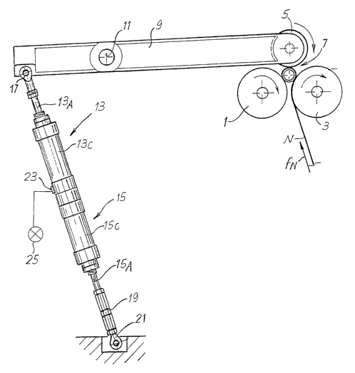
With initial reference to Figures 1 to 3, the rewinding machine comprises a
first and a second winding roller 1, 3 with parallel axes and defining, with a
third
winding roller 5, a winding cradle 7. While the winding rollers 1 and 3 have
(in this
example) a fixed axis, the third winding roller 5 is carried by a pair of
oscillating
arms 9 hinged about ari oscillafiion axis 11. Therefore, the axis of the third
winding
roller 5 is moving so that the roller 5 can move away from and towards the
rollers 1
and 3.
The oscillatory movement of the oscillating arms 9 is controlled by a pair of
piston-cylinder actuators 13 and 15, of which 13C and 15C indicate the
cylinders
and 13A and 15A indicate the rods of the respective pistons. The two piston-
cylinder actuators 13, 15 are aligned and connected rigidly with each other at
the
back ends of the respective cylinders 13C, 15C.
The rod 13A of the actuator 13 is hinged in 17 to one of the arms 9, on the
opposite side of the roller 5 in respect of the oscillation axis 11. The rod
15A is
connected, by means of a tie-rod with adjustable length 19, to a fixed point
21 of
the machine structure, not shown in detail.
A sensor 23 equipped with an indicator 25, for example a lamp, is
associated with the piston-cylinder 13. This sensor detects the stroke end
position,
that is of maximum retraction, of the actuator 13, for the purposes described
herein.
Operation of the machine described hereinbefore is as follows: Figure 1
shows the initial phase of winding of a first log R of web material N. A few
turns of
material N are wound around the winding core or spindle, the outermost of
which
CA 02492713 2005-O1-14
WO 2004/063067 PCT/IT2004/000005
_7_
is in contact with the three rollers 1, 3, 5, which may all advantageously be
motorized, although other solutions, such as one idle roller, are possible.
The roller
is pressed against the log being formed with a pressure determiried by the
pressure of the fluid inside the actuator 13. This pressure may suitably be
5 maintained more or less constant or (when the machine has a more complex
configuration) may vary during winding, for example as a function of the
angular
position of the pair of oscillating arms 9. In general, the force applied by
the
actuator 13 partly compensates the weight of the roller 5, so that the stress
applied
to the log being formed is lower than the stress that would be applied by the
overall weight of the roller 5. In any case, the assembly' 13, 15 controls
action of
the winding roller 5 on the log being formed, in the sense that through it
stress that
can be determined and adjusted according to production needs is applied to the
log.
Figure 2 shows a conclusive phase of winding. The log R has increased in
diameter and consequently the arms 9 have rotated counter-clockwise (in the
drawing) to allow lifting of the winding roller 5 with moving axis. The piston-
.cylinder
actuator 13 has retracted. to allow this movement, while the actuator 15 has
remained completely extended. Figure 2 shows the completely retracted position
of the piston cylinder actuator 13. Nonetheless, winding of the log R is still
not
complete, as the set quantity of web material has not yet been reached. The
final
turns of rnieb material N are wound maintaining the roller 5 in the position
in Figure
2 and thus effectively preventing an increase in the diameter of the log R.
These
final turns will therefore be wound with increased compactness in respect of
the
previous ones. The length of web material wound on the log may be measured in
any known way, for example by an encoder on one of the rollers around which
the
web material is driven.
In Figure 3 the log being formed R has been completed.' To allow the
exchange phase, that is unloading the finished log R and 'introducing a new
winding core into the winding cradle 7 among other things, the moving winding
roller 5 must be lifted further in respect of the position in Figure 2. The
actuator 15
is used for this purpose. As can be seen in Figure 3, retraction of the
actuator 15
causes further lifting of the roller 5, thus allowing unloading of the
completed log R
from the cradle 7. Operations to cut or sever the web material, unload the
log,
insert the new winding core and adhesion of the initial free end to the new
core to
CA 02492713 2005-O1-14
WO 2004/063067 PCT/IT2004/000005
_$_
start winding a subsequent log are not described in detail as these may take
place
in any way known to those skilled in the art.
Following the exchange phase a new log starts to be wound with the same
procedures described herein.
It may be necessary to change the quantity of web material wound on each
log R, or the density of winding, modifying the pressure applied by the roller
5 on
the log being formed with consequent variation in the compactness .of winding
the
various turns. By varying these parameters the diameter of the final log
obtained
changes. For example, if it is desired to obtain less compact logs with the
same
_ ,
length of material wound, the pressure inside the cylinder 13C of the actuator
13
will be increased, in order to reduce the weight of the roller 5 on the log
being
formed. Consequently, the final diameter of the logs will increase. On the
other
hand, it may be desirable to wind a greater quantity of web material N on each
fog
R with the same winding density, with a consequent increase in the final
diameter.
As the final diameter is set by the stroke end position of the actuator 13,
the
adjustable tie-rod 19 is provided to allow modification of these winding
parameters.
if it is desired to wind a larger quantity of web material and/or to obtain
less
compact winding and, therefore, to reach larger final winding diameters , the
tie-
rod 19 is shortened, so that the final position of the winding roller 5 when
the
actuator 13 has reached its stroke end position will be higher, that is
farther from
the winding rollers 1 and 3.
The sensor 23 and the indicator 25 are provided to facilitate setting of the
machine by adjusting the length of the tie-rod 19, with regard to the final
diameter
of the log. The sensor 23 and the indicator 25 may be . used in combination or
alternatively to modify the operating conditions of the machine with regard to
winding compactness, which is set and modified by acting on the pressure value
inside the cylinder 13C.
The sensor 23 and the indicator 25 inform the operator when the actuator
13 has reached is stroke end position and therefore when the final diameter of
the
log R has been reached (layout in Figure 2). The operator can tell, for
example by
means of a counter or a suitable interface known per se, how much web material
has been wound at the time in which this stroke end position is reached and
how
much material must still be wound in the final turns. If the operator sees
that with
the winding parameters set (thickness of the web material N, winding pressure,
CA 02492713 2005-O1-14
WO 2004/063067 PCT/IT2004/000005
length of material to be wound), the stroke end position of the actuator 13
and
hence the final diameter are reached too soon and therefore too many external
turns of the log will be wound very compactly, the operator will shorten the
tie-rod
19. An inverse lengthening operation will be performed in the opposite
situation;
that is, for example, if the quantity of web material wound is inadequate to
attain
the final diameter of the log.
When the set quantity of web material is attained without the moving roller 5
having reached the final position and therefore the completed log has not
reached
the diameter set for correct packaging, the operator will increase the
pressure
value inside the cylinder 13C.
Figure 4 shows a modified embodiment, wherein equivalent or
corresponding parts are indicated with the same reference numerals used in
Figures 1 to 3. In this case, the two actuators that control movement of the
winding
roller 5 are constituted by a single cylinder 15, inside which two pistons
13A, 15A
slide., each equipped with a respective rod. From the position in Figure 4,
the roller
5 is lifted during winding of the log and increase of its diameter, with
retraction of
the piston 13A inside the cylinder 15C. The stroke end position is defined by
the
position of the rod of the piston 15A. When this position is reached, the log
is
completed and can be unloaded by moving the roller 5 farther from the rollers
1
and 3 through simultaneous retraction of the two pistons 13A, 15A inside the
cylinder 15C.
..The arrangement of the actuators - or in general of the control member of
the roller with moving axis - may differ from the one illustrated. For
example, the
actuators may be disposed above rather than below the oscillating arm 9 and/or
can be hinged in an intermediate point between the axis of the roller 5 and
the axis
of oscillation of the arm. Consequently, the stroke end positions will differ.
It is understood that the drawing purely shows a practical embodiment of
the invention, the forms and arrangements of which may vary without however
departing from the scope of the concept underlying the invention. Any
reference
numerals in the attached claims are provided purely to facilitate reading in
the light
of the description hereinbefore and of the attached drawings and do not limit
the
scope of protection whatsoever.