Note: Descriptions are shown in the official language in which they were submitted.
CA 02492773 2005-O1-17
RING BINDER MECHANISM WITH REINFORCED HINGE PLATES
BACKGROUND OF THE INVENTION
[0001] This invention relates to a ring binder mechanism for retaining
loose-leaf pages, and in particular to an improved mechanism having hinge
plates that are reinforced.
[0002] As is known in the art, a typical ring binder mechanism retains
loose-leaf pages, such as hole-punched papers, in a file or notebook. It
generally features multiple rings, each including two half ring members that
mount on two adjacent hinge plates. The hinge plates join together about a
pivot
axis and loosely pivot within an elongate housing, allowing the ring members
mounted thereon to move between an open position where papers may be
added or removed and a closed position where papers are retained and can
move along the rings. An operator may typically open or close the ring members
by manually pulling the ring members apart or pushing them together. In
addition, in some mechanisms the operator can move levers located at ends of
the housing to open or close the ring members. In these mechanisms, the
levers often engage the hinge plates and drive them between the open and
closed position.
(0003] Conventionally, the mechanism is secured to a cover of the file or
notebook by a pair of rivets, generally located toward longitudinal ends of
the
housing. Each rivet attaches to a corresponding eyelet of the housing, spacing
the mechanism from the cover and allowing the hinge plates to pivot without
contacting the cover. The eyelets provide a surface to receive the rivet so
that
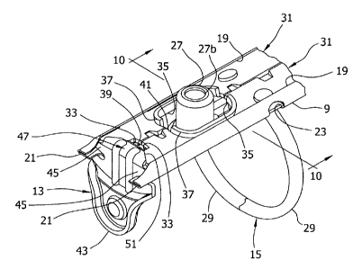
the rivet does not pull through the housing when the mechanism is secured to
the cover. Alternatively, in some mechanisms the eyelets are replaced by
barrel
bushings or other suitable mounting structure. The barrel bushings are
substantially similar to the eyelets, but are generally wider. Eyelets and
barrel
bushings are described, and further distinguished, in commonly assigned U.S.
Patent No. 5,879,097, the entire disclosure of which is hereby incorporated by
reference.
[0004] To accommodate the eyelets (or the barrel bushings), the hinge
plates usually have openings therein (toward their longitudinal ends) that
allow
the mounting structure to pass through the hinge plates without interfering
with
their operation. These openings, however, may weaken the hinge plates near
their ends. This is a particular concern in ring binder mechanisms having the
wider barrel bushings for receiving the rivets and in mechanisms having a
1
CA 02492773 2005-O1-17
relatively narrow housing. In both mechanisms, the openings generally comprise
a substantially large portion of the width of the hinge plates. Accordingly,
when
these mechanisms use levers located at the ends of the housing to pivot the
hinge plates, the driving forces imparted by the levers may cause the ends of
the
hinge plates to bend rather than pivot about their hinge axis, potentially
leaving
the hinge plates inoperable.
[0005] One solution to this problem is to keep the openings relatively
small. But with small openings, the size of the mounting structure must be
correspondingly small. Another solution is to construct the hinge plates from
larger gauge metal. But this can make fabrication of the hinge plates more
difficult and increase the cost of production. Thus, a reinforced hinge plate
that
resists bending or deforming at its ends would be desirable.
[0006] It is generally known in the art to strengthen hinge plates. In
particular, it is known to preform the hinge plates with circular indentations
around each ring member attachment hole and with linear indentations between
consecutive attachment holes. Examples of these strengthened hinge plates are
shown in U.S. Patent Nos. 5,368,407 and 5,378,073. But the indentations of
these plates are centrally located along the plates and therefore do not
effectively provide reinforcement to ends of the hinge plates, adjacent to
both the
lever and the mounting structure.
[0007] Accordingly, there is still a need for an improved ring binder
mechanism having hinge plates that are reinforced so that they do not bend or
deform adjacent the lever during operation.
SUMMARY OF THE INVENTION
[0008] The present invention provides an improved ring binder
mechanism having hinge plates that are rigidified near the lever for
preventing
the hinge plates from bending or deforming during operation. In general, a
ring
binder mechanism of the present invention retains loose-leaf pages. The
mechanism comprises an elongate housing and hinge plates supported by the
housing for relative pivoting motion. The mechanism also comprises at least
one
ring, which includes first and second ring members. The first ring member is
mounted on one of the hinge plates and moves with the pivoting motion of that
hinge plate between a closed position and an open position. In the closed
position, the two ring members of the ring form a substantially continuous,
closed
loop for allowing loose-leaf pages retained by the ring to be moved along the
ring
from one ring member to the other. In the open position, the two ring members
2
CA 02492773 2005-O1-17
of the ring form a discontinuous, open loop for adding or removing loose-leaf
pages from the ring. A lever is mounted on the housing for movement relative
to
the housing and is adapted for engaging at least one of the hinge plates for
moving the ring members from one of the open position and closed position to
the other of the open position and closed position. Moreover, at least one of
the
hinge plates of the mechanism is formed with a reinforcing structure located
generally adjacent to the lever for rigidifying the hinge plate adjacent the
lever.
[0009] Other objects and features of the present invention will be in part
apparent and in part pointed out hereinafter.
BRIEF DESCRIPTION OF THE DRAWINGS
[0010] FIG. 1 is a perspective of a notebook incorporating a ring binder
mechanism of the present invention;
[0011] FIG. 2 is a perspective of the ring binder mechanism of the
present invention with ring members at a closed position;
[0012] FIG. 3 is an inverted exploded perspective of the mechanism of
FIG. 2;
[0013] FIG. 4A is an outer longitudinal edge margin side elevation of a
hinge plate of the mechanism of FIG. 3;
[0014] FIG. 4B is a top plan of the hinge plate of FIG. 4A;
[0015] FIG. 5A is an enlarged fragmentary perspective of the hinge plate
of FIG. 4B;
[0016] FIG. 5B is a section taken on line 5B-5B of FIG. 5A;
[0017] FIG. 6 is a perspective similar to FIG. 2 with the mechanism
inverted;
[0018] FIG. 7 is the perspective of FIG. 6 but with the ring members at an
open position;
[0019] FIG. 8A is an enlarged fragmentary perspective of the mechanism
of FIG. 2 with a housing, barrel bushings, and ring members removed;
[0020] FIG. 8B is a section taken on line 8B-8B of FIG. 8A;
[0021] FIG. 9 is an enlarged fragmentary perspective of the mechanism
of FIG. 6;
[0022] FIG. 10 is an inverted section taken on line 10-10 of FIG. 9 but
with a rivet and a spine of the notebook also shown;
[0023] FIG. 11 is an enlarged fragmentary perspective similar to FIG. 9
with an eyelet attached to the mechanism; and
3
CA 02492773 2005-O1-17
[0024] FIG. 12 is an inverted section taken on line 12-12 of FIG. 11 but
with the rivet and the spine also shown.
[0025] Corresponding reference characters indicate corresponding parts
throughout the several views of the drawings.
DETAILED DESCRIPTION OF THE INVENTION
[0026] This application contains subject matter in common with co-
assigned, co-pending design patent application Serial No. filed
simultaneously herewith for A Reinforced Hinge Plate For A Ring Mechanism, the
entire disclosure of which is hereby incorporated by reference.
[0027] Referring now to the drawings, and particularly to Fig. 1, a ring
binder mechanism according to the present invention is designated generally by
reference numeral 1. The mechanism 1 is shown mounted on a spine 3 of a
notebook 4 having a front cover 5 and a back cover 7 hingedly attached to the
spine. The front and back covers 5, 7 are movable to selectively cover or
expose
pages (not shown) retained by the mechanism 1. Ring binder mechanisms
mounted on surfaces other than a notebook, however, do not depart from the
scope of the present invention.
[0028] As shown in Figs. 1 and 2, the ring binder mechanism 1 includes
an elongate housing 9 that supports two substantially similar actuating levers
(each designated generally by reference numeral 13) and three rings (each
designated generally by reference numeral 15). The housing 9 is symmetrical
with a roughly arch-shaped cross section (see Figs. 10 and 12) and includes a
longitudinal axis, two transversely opposite longitudinally extending edges,
and
two longitudinal ends. Each lever 13 pivotally mounts on the housing 9,
generally
at an opposite longitudinal end, for controlling movement of the rings 15
between
a closed position (see Figs. 1, 2, and 6) and an open position (see Fig. 7).
[0029] As best shown in Fig. 3, a bent under rim 19 is formed along each
longitudinal edge of the housing 9, extending the full length of the housing
from
one longitudinal end to the other. Each end of the two bent under rims 19 is
pinched together with a portion of an upper surface of the housing 9 to form
four
pockets (each pocket being designated by reference numeral 21). Accordingly,
there are iwo pockets 21 extending longitudinally outward from each
longitudinal
end of the housing 9. Six total slots 23 are positioned along the two bent
under
rims 19. The slots 23 are arranged in three transversely opposed pairs with
each
pair receiving one of the rings 15 therethrough, allowing each ring to move
laterally of the housing 9 for opening and closing. Two additional circular
4
CA 02492773 2005-O1-17
openings 25 are provided in the upper surface of the housing 9, near the
longitudinal ends, each receiving and attaching mounting structure to the
housing
9 (in the mechanism illustrated in Figs. 1-10, the mounting structure includes
two
barrel bushings 27), supporting the mechanism 1 above the spine 3 of the
notebook. It is envisioned that the housing of the present invention is made
of
metal, but it may be made of any other suitable material that is sufficiently
rigid to
provide a stable mount for components of the mechanism. In addition, different
shaped housings, including asymmetrical ones, do not depart from the scope of
this invention.
[0030] Referring now to Figs. 2, 3, 6, and 7, the rings 15 each include two
ring members 29 which are movable relative to one another between a closed
position and an open position. In the closed position, the ring members 29
form a
substantially continuous, closed, ring or loop for retaining loose-leaf pages
and
for allowing the pages to move along the rings 15 from one ring member 29 to
the
other. In the open position, the ring members 29 form a discontinuous, open
loop
suitable for adding or removing pages. It is envisioned that the ring members
are
formed of a conventional, cylindrical rod of suitable material, such as steel.
But it
is understood that ring members having a different cross section or ring
members
made of different material do not depart from the scope of the present
invention.
Although in the illustrated mechanism both ring members can move, mechanisms
having one movable ring member and one fixed do not depart from the scope of
the invention. In addition, mechanisms with more or less than three rings or
with
rings that form other shapes, such as slanted "D" shapes, when ring members
are closed, do not depart from the scope of this invention.
[0031] As shown in Figs. 3-5B, the two ring members 29 of each ring 15
are mounted opposite each other on one of a pair of hinge plates (each hinge
plate being designated generally by reference numeral 31). The hinge plates 31
are each thin and elongate, having an inner and an outer longitudinal edge
margin and two longitudinal ends. Each hinge plate 31 additionally includes
two
squared notches 33 and two rounded cutouts 35, each of which are located along
the inner longitudinal edge margin of the hinge plate. The two notches 33 are
each located at an opposite longitudinal end of the hinge plate 31, and the
two
cutouts 35 are each located inward from a one of the respective notches 33 but
still generally adjacent the hinge plates' ends. The cutouts 35 are each
somewhat elongated and have a relatively straight side with two rounded ends.
The side is receded into the hinge plate 31 and is roughly parallel to the
hinge
plate's inner and outer longitudinal edge margins. Reinforcing structure
extends
5
CA 02492773 2005-O1-17
substantially around a perimeter of each cutout 35 for reinforcing the hinge
plates
31 adjacent the cutouts. In the illustrated mechanism 1, this reinforcing
structure
is an upstanding rib 37, which will be discussed in more detail hereinafter.
Mechanisms having reinforcing structure with a different shape than that
described and illustrated herein do not depart from the scope of the present
invention.
[0032] Now referring to Figs. 6, 7, and 9, the hinge plates 31 attach to one
another in parallel arrangement along their inner longitudinal edge margins,
forming a central hinge having a pivot axis. The housing 9 loosely receives
the
outer longitudinal edge margins of the interconnected hinge plates 31 above
its
two bent under rims 19. Thus, the hinge plates 31 are retained on the housing
9
while the outer longitudinal edge margins are free to move within the rims 19.
Corresponding notches 33 of the adjoining hinge plates align to form two box-
shaped recesses 39 at opposite longitudinal ends of the plates 31. These
recesses 39 are sized and shaped to interact with the actuating levers 13, as
will
be described in more detail hereinafter. Similarly, corresponding cutouts 35
align
to form two roughly oval openings 41, each sized and shaped for receiving one
of
the barrel bushings 27 through the hinge plates 31. The ribs 37 of each cutout
35
align to substantially extend around a perimeter of each opening 41,
rigidifying
the interconnected hinge plates adjacent the openings and preventing them from
bending during operation. Mechanisms having reinforcing structure that does
not
substantially encompass an opening do not depart from the scope of the present
invention. Furthermore, in the illustrated mechanism 1 the box-shaped recesses
39 and the oval openings 41 are both symmetrically positioned about the pivot
axis of the interconnected hinge plates 31. However, mechanisms in which
openings and recesses are positioned differently about a pivot axis of
interconnected hinge plates do not depart from the scope of the present
invention.
[0033] In this mechanism 1, the housing 9 is slightly narrower than the
joined hinge plates 31 when the hinge plates are in a coplanar position (i.e.,
an
angle between exterior surfaces of the hinge plates is 180°). So as the
hinge
plates 31 pivot through this position, they deform the resilient housing 9 and
cause a spring force in the housing that urges the hinge plates 31 to pivot
away
from the coplanar position, either closing the ring members 29 (i.e., moving
the
pivot axis down and away from the housing's upper surface (Fig. 6)) or opening
them (i.e., moving the pivot axis up and toward the housing's upper surface
(Fig.
7)). Moreover, when the ring members 29 are closed, this spring force resists
6
CA 02492773 2005-O1-17
hinge plate movement and clamps the ring members together. When the ring
members 29 are open, the spring force holds them apart.
(0034] The two actuating levers 13 are generally shown in Figs. 2, 3, 8A-
9, and 11. Each includes a relatively flat head 43 that extends upward from
the
lever 13, generally above the housing 9, for grasping to pivot the lever. Each
additionally includes two lateral arms, each designated by reference numeral
45,
and a cam, designated generally by reference numeral 47. As best shown in
Figs. 8A-9 and 11, the lateral arms 45 extend laterally outward from opposite
sides of each lever 13 below the flat head 43. The two arms 45 of each lever
loosely fit within the two pockets 21 located at each longitudinal end of the
housing 9, allowing the levers 13 to pivot within the pockets 21 relative to
the
housing about an axis transverse to the housing. The cam 47 of each lever is
integrally attached to the lever 13 below the lateral arms 45. It extends
downward from the arms 45 and curves outward from the flat head 43, fitting
into
one of the respective box-shaped recesses 39 of the hinge plates. An enlarged
tab 49 of each cam fits loosely over the interconnected hinge plates 31 while
a
base 51 of each cam rests below the plates. Together, the tab 49 and base 51
releasably lock the hinge plates 31 therebetween for operable engagement to
control the pivoting motion of the hinge plates that close and open the ring
members 29. In operation to close the ring members 29, the levers 13 are
pivoted upward and inward. The tabs 49 engage a top surface of the hinge
plates 31 and pull the pivot axis of the plates downward. To open the ring
members 29, the levers 13 are pivoted outward and downward. The bases 51
engage a bottom surface of the hinge plates 31 and push the pivot axis of the
plates upward. Mechanisms (not shown) having levers with different shapes or
levers pivotally attached to a housing differently do not depart from the
scope of
the present invention. In addition, mechanisms having only one lever for
driving
the hinge plates do not depart from the scope of the present invention.
(0035] Referring now to Figs. 3, 6, 7, 9, and 10, the two barrel bushings
27 are located adjacent the levers 13 and space the ring binder mechanism 1
off
the notebook 4 so that the hinge plates 31 can pivot without engaging the
spine
3. In this position, the bushings 27 align with the oval openings 41 of the
interconnected hinge plates 31 and pass through the hinge plates without
interfering with their operation. Each barrel bushing 27 is tubular in shape
and
has two open ends. At a first end, the barrel bushing 27 includes a deformable
lip 27a that attaches the bushing to one of the circular openings 25 in the
upper
surface of the housing 9. At a second end, the bushing 27 includes a circular
rim
7
CA 02492773 2005-O1-17
27b that is folded inward of the bushing for supporting the bushing on the
spine 3.
As shown in Fig. 10, rivets 53 pass through each of the barrel bushings 27
(only
one of the rivets and barrel bushings is visible) for securing the ring binder
mechanism 1 to the notebook 4. One end of each rivet 53 attaches to the folded
rim 27b of the barrel bushing, and a second end of each rivet 53 attaches to
the
notebook's spine 3. Mechanisms secured to a notebook or other surface
differently than described and illustrated herein do not depart from the scope
of
the present invention.
[0036] Figures 11 and 12 show an alternative construction of the ring
binder mechanism 1, which is substantially as described above and illustrated
in
Figs. 1-10. But in this construction, the mounting structure includes two
eyelets
55 instead of two barrel bushings 27. As with the barrel bushings 27
previously
described, each eyelet 55 is located toward a longitudinal end of the housing
9
and passes through one of the oval openings 41 of the hinge plates, allowing
the
hinge plates 31 to pivot relative to the eyelets 55 without engaging them.
Together, the two eyelets support the mechanism 1 above the notebook 4 and
prevent the hinge plates 31 from engaging the spine 3 as they pivot. Each
eyelet
55 is also tubular in shape and includes two open longitudinal ends. A first
end
includes a deformable lip 55a for attaching the eyelet 55 to one of the
circular
openings 25 in the upper surface of the housing 9. A second end includes a
circular rim 55b that is folded outward of the eyelet 55 for supporting the
eyelet
on the spine 3 of the notebook. As shown in Fig. 12, a rivet 53 also passes
through each eyelet 55 for securing the mechanism 1 to the notebook 4. But the
eyelets are different from the barrel bushings 27 in that they have a smaller
diameter. Therefore, the rivets 53 generally attach to the deformable lips 55a
of
the eyelets when securing the mechanism 1 to the notebook's spine 3.
[0037] Figures 4A-6 illustrate the upstanding ribs 37 of the mechanism 1.
As previously described, they substantially encompass each oval opening 41 of
the interconnected hinge plates 31. Each rib 37 is preferably formed as one
piece with the respective hinge plate 31, and in particular, it is envisioned
that
each rib 37 is formed by bending the surface of each hinge plate 31 downward,
away from the housing 9, approximately 90° so that the rib has a height
H that is
preferably equal to or greater than the thickness of the hinge plate (Fig.
5B). It is
to be understood, however, that mechanisms having ribs or other reinforcing
structure formed by bending a surface of a hinge plate upward, toward a
housing,
or formed separately from a hinge plate do not depart from the scope of the
present invention. In addition, mechanisms having ribs with a height that is
less
8
CA 02492773 2005-O1-17
than a thickness of a hinge plate do not depart from the scope of the present
invention. In the illustrated mechanism 1, the height H of each rib is
approximately 0.03 inches (approximately 0.0762 cm), but mechanisms having
ribs with heights greater than or less than 0.03 inches (0.0762 cm) do not
depart
from the scope of the present invention.
(0038] As described and illustrated herein, it is to be understood that the
upstanding ribs 37 of the present invention provide additional thickness to
the
hinge plates 31 around the oval openings 41 therein. Accordingly, they
effectively reinforce the hinge plates 31 adjacent their longitudinal ends.
Thus, in
mechanisms having actuating levers located at ends of a housing and mounting
structure located adjacent those levers, as in the mechanism 1 described and
illustrated herein, the reinforced hinge plates of the present invention would
prevent driving forces of the levers from bending or deforming the hinge
plates
during operation. The reinforced hinge plates reliably pivot about their hinge
axis
when engaged by the levers.
(0039] The reinforced hinge plates are particularly beneficial in
mechanisms having barrel bushings (or other mounting structure) mounting the
mechanism on a notebook and in mechanisms having narrow housings for
mounting on a narrow spine. In both, openings of the hinge plates which
accommodate the barrel bushings may comprise a substantially large portion of
the width of the hinge plates. This may cause the hinge plates to fail or
deflect
substantially at the openings during operation. However, the reinforced hinge
plates prevent this from happening. They resist the bending forces imparted on
the hinge plates when driven by the levers thereby preventing the plates from
deforming. A further benefit of these reinforced hinge plates is that they may
be
constructed of smaller gauge metal because the ribs strengthen the plates at
potential weak areas adjacent the openings. Thus, production costs may be
lower for ring binder mechanisms incorporating such reinforced hinge plates.
(0040] Components of the mechanism of the present invention are made
of a suitable rigid material, such as metal (e.g. steel). But mechanisms made
of a
non-metallic material, specifically including plastic, do not depart from the
scope
of this invention.
[0041] When introducing elements of the present invention or the
preferred embodiments) thereof, the articles "a", "an", "the" and "said" are
intended to mean that there are one or more of the elements. The terms
"comprising", "including" and "having" are intended to be inclusive and mean
that
there may be additional elements other than the listed elements. Moreover, the
9
CA 02492773 2005-O1-17
use of "up" and "down" and variations thereof is made for convenience, but
does
not require any particular orientation of the components.
[0042] As various changes could be made in the above without departing
from the scope of the invention, it is intended that all matter contained in
the
above description and shown in the accompanying drawings shall be interpreted
as illustrative and not in a limiting sense.