Note: Descriptions are shown in the official language in which they were submitted.
CA 02492950 2006-09-21
77496-109D
1
TRANSVERSE MAGNETIC FIELD ANNEALED AMORPHOUS
MAGNETOMECHANICAL ELEMENTS FOR USE IN ELECTRONIC ARTICLE
SURVEILLLANCE SYSTEM AND METHOD OF MAKING SAME
FIELD OF THE INVENTION
This invention relates to magnetomechanical
markers used in electronic article surveillance (EAS)
systems, and methods of making same.
BACKGROUND OF THE INVENTION
It is well known to provide electronic article
surveillance systems to prevent or deter theft of
merchandise from retail establishments. In a typical
system, markers designed to interact with an electromagnetic
or magnetic field placed at the store exit are secured to
articles of merchandise. If a marker is brought into the
field or "interrogation zone", the presence of the marker is
detected and an alarm is generated. Some markers of this
type are intended to be removed at the checkout counter upon
payment for the merchandise. Other types of markers are
deactivated upon checkout by a deactivation device which
changes an electromagnetic or magnetic characteristic of the
marker so that the marker will no longer be detectable at
the interrogation zone.
One type of magnetic EAS system is referred to as
a harmonic system because it is based on the principle that
a magnetic material passing through an electromagnetic field
having a selected frequency disturbs the field and produces
harmonic perturbations of the selected frequency. The
detection system is tuned to recognize certain harmonic
frequencies and, if present, causes an alarm. The harmonic
frequencies generated are a
CA 02492950 1995-04-11
77496-109D
2
function of the degree of non-linearity of the hysteresis
loop of the magnetic material.
Another type of EAS system employs
magnetomechanical markers that include a magnetostrictive
element. For example, U.S. Patent No. 4,510,489, issued to
Anderson et al., discloses a marker formed of a ribbon-
shaped length of a magnetostrictive amorphous material
contained in an elongated housing in proximity to a biasing
magnetic element. The magnetostrictive element is fabricated
such that it is resonant at a predetermined frequency when
the biasing element has been magnetized to a certain level.
At the interrogation zone, a suitable oscillator provides an
ac magnetic field at the predetermined frequency, and the
marker mechanically resonates at this frequency upon
exposure to the field when the biasing element has been
magnetized to a certain level.
According to one technique disclosed in the
Anderson et al. patent, the marker has, in addition to the
aforesaid resonant frequency, an "anti-resonant frequency"
at which the stored mechanical energy resulting from
magneto-mechanical coupling is near zero. An interrogation
circuit which provides the magnetic field at the
interrogation zone is swept through a frequency range that
includes the marker's resonant and anti-resonant
frequencies, and receiving circuitry is provided at the
interrogation zone to detect the marker's characteristic
signature by detecting a peak transmitted energy level which
occurs at the resonant frequency, and a valley level at the
anti-resonant frequency.
Anderson et al. also propose that the
magnetostrictive element be subjected to annealing over a
CA 02492950 1995-04-11
77496-109D
3
period of 7-120 mins. at a temperature in the range of about
300 -450 C in the presence of a saturating transverse
magnetic field of a few hundred oersted to enhance a
magneto-mechanical coupling factor k which is related to the
difference in frequency between the resonant and anti-
resonant frequencies of the marker. According to Anderson
et al., a larger coupling factor k increases the
detectability of the marker's characteristic signature.
In still another surveillance system proposed by
Anderson et al., a magnetostrictive marker is used with an
interrogation frequency that is not swept, but rather
remains at the marker's resonant frequency. The
interrogation field at this frequency is provided in pulses
or bursts. A marker present in the interrogation field is
excited by each burst, and after each burst is over, the
marker undergoes a damped mechanical oscillation. The
resulting signal radiated by the marker is detected by
detecting circuitry which is synchronized with the
interrogation circuit and arranged to be active during the
quiet periods after bursts. EAS systems of this pulsed-field
type are sold by the assignee of this application under the
brand name "Ultra*Max" and are in widespread use.
For markers used in pulsed-interrogation systems,
the amplitude and duration of oscillations which the member
continues to exhibit after the end of each excitation pulse
are very important. The greater the amplitude and duration
of the residual oscillations (known as "ring down"), the
more unique is the signal during the quiet period in the
interrogating zone and therefore the easier it is for the
marker to be detected by the detecting circuitry.
CA 02492950 1995-04-11
77496-109D
4
Deactivation of magnetomechanical markers is
typically performed by degaussing the biasing element, so
that the magnetostrictive element ceases to be mechanically
resonant or its resonant frequency is changed. However, when
the biasing element is degaussed, although the marker is no
longer detectable in a magnetomechanical surveillance
system, the magnetostrictive element may nevertheless act as
an amorphous magnetic element which can still produce
harmonic frequencies in response to an electromagnetic
interrogating field. This is undesirable because after a
purchaser of an item bearing the magnetomechanical marker
has had the marker degaussed at the checkout counter, that
purchaser may then enter another retail shop where a
harmonic EAS system may be in use and where it would be
possible for the degaussed marker to set off an alarm
because it may generate harmonic frequencies in response to
an interrogation signal in the second retail store.
The present inventors have found that when
conventional magnetostrictive materials used in a pulsed
interrogation system are annealed in the presence of a
transverse magnetic field, the ring down characteristic of
the materials is adversely affected. The time of ring down
is substantially reduced thereby rendering the marker less
unique as a magnetomechanical marker.
U.S. Patent No. 5,252,144, issued to Martis, has
proposed that various magnetostrictive materials be annealed
to improve the ring down characteristics thereof. However,
unlike the present invention, the Martis patent does not
disclose applying a magnetic field during heating.
CA 02492950 1995-04-11
77496-109D
OBJECTS AND SUMMARY OF THE INVENTION
It is accordingly a primary object of the
invention to provide a magnetomechanical marker that is
suitable for use in a pulsed-field EAS interrogation system.
5 It is a further object to provide such a marker that, when
deactivated, does not generate harmonic signals of
substantial amplitude in response to interrogation by
harmonic detection EAS systems.
It is another object of the invention to provide a
magnetostrictive marker that is easier to manufacture than
conventional magnetomechanical markers.
It is yet another object of the invention to
provide a magnetomechanical marker that is thinner than
conventional magnetomechanical markers.
It is still another object of the invention to
provide a magnetomechanical marker with improved ring down
characteristics.
According to an aspect of the invention, an
amorphous ferromagnetic material is cut into fixed length
strips and then annealed. The annealing process applied to
the material includes applying a saturating magnetic field
in a direction transverse to
CA 02492950 1995-04-11
77496-109D
6
the longitudinal axis of a ribbon-shaped member formed of
the material, while heating the material and then cooling
the material relatively slowly while still in the transverse
magnetic field.
According to another aspect of the invention, the
material is formed of iron, cobalt, silicon and boron and
includes at least 30% cobalt by atomic percent.
According to another aspect of the invention, the
annealing process may include heating the material at a
temperature within the range of 3000 to 540 C for at least
5 minutes.
In accordance with the invention, there is
provided a method of fabricating a marker for use in a
magnetomechanical electronic article surveillance system,
the method comprising the steps of: applying a saturating
magnetic field to an amorphous magnetic element; heating
said element at a temperature in the range of 4600 to 540 C
for at least 5 minutes during application of said magnetic
field; and allowing the element to cool to room temperature.
According to another aspect the invention provides
a marker for use in a magnetomechanical electronic article
surveillance system, comprising a magnetostrictive element
formed by annealing an amorphous magnetic member by applying
a saturating magnetic field to said member while heating
said member at a temperature in the range of 460 C to 540 C
for at least 5 minutes.
In another aspect the invention provides a
magnetomechanical electronic article surveillance system
comprising: (a) generating means for generating an
electromagnetic field alternating at a selected frequency in
CA 02492950 2006-09-21
77496-109D
6a
an interrogation zone, said generating means including an
interrogation coil; (b) a marker secured to an article
appointed for passage through said interrogation zone, said
marker including an amorphous magnetostrictive element
formed by annealing an amorphous magnetic member by applying
a saturating magnetic field to said member while heating
said member at a temperature in the range of 460 C to 540 C
for at least 5 minutes, said marker also including a biasing
element located adjacent to said magnetostrictive element,
said biasing element being magnetically biased to cause said
magnetostrictive element to be mechanically resonant when
exposed to said alternating field; and (c) detecting means
for detecting said mechanical resonance of said
magnetostrictive element.
According to another aspect there is provided a
method of forming a magnetostrictive element, the method
comprising the steps of: (a) providing an amorphous magnetic
material; and (b) heat treating said material at a
temperature range of 460 C to 540 C for at least 5 minutes
in the presence of a saturating magnetic field, said heat
treating being performed so as to smooth a hysteresis
characteristic of said material.
According to another aspect there is provided a
method of making a magnetostrictive element for use as a
marker in a magnetomechanical electronic article system
comprising: (a) selecting an amorphous magnetic material;
(b) cutting the said material to a strip having a fixed
uniform length preselected to ultimately make the strip
mechanically resonant at a desired frequency; (c) annealing
the said strip at a temperature between 300 C and 540 C for
a period of time between 2 and 60 minutes in a transverse
magnetic field having a strength of at least 500 oersteds;
CA 02492950 1995-04-11
77496-109D
6b
and (d) cooling said strip to room temperature for a period
of not less than two minutes in a transverse magnetic field
having a strength of at least 500 oersteds; whereby said
strip exhibits magnetostrictive properties having the said
desired mechanical resonant frequency and has a unique
detectable signal during a ring down period.
According to another aspect there is provided a
marker for use in a magnetomechanical electronic article
surveillance system, comprising a magnetostrictive element
made by selecting an amorphous magnetic material, cutting
said material to a strip having a fixed uniform length
preselected to ultimately make the strip mechanically
resonant at a desired frequency, annealing the said strip at
a temperature between 300 C and 540 C for a period of time
between 2 and 60 minutes in a transverse magnetic field, and
cooling said strip to room temperature over a period of not
less than two minutes in a transverse magnetic field having
a strength of at least 500 oersteds; wherein said strip
exhibits magnetostrictive properties having the said desired
mechanical resonant frequency and has a unique detectable
signal during a ring down period.
According to another aspect there is provided a
magnetomechanical electronic article surveillance system
comprising: (a) generating means for generating an
electromagnetic field alternating at a selected frequency in
an interrogation zone, said generating means including an
interrogation coil; (b) a marker secured to an article
appointed for passage through said interrogation zone, said
marker including a magnetostrictive strip made by selecting
an amorphous magnetic material, cutting said material to a
strip having a fixed uniform length preselected to
CA 02492950 1995-04-11
77496-109D
6c
ultimately make the strip mechanically resonant at said
selected frequency, annealing the said strip at a
temperature between 300 C and 540 C for a period of time
between 2 and 60 minutes in a transverse magnetic field
having a strength of at least 500 oersteds and cooling said
strip to room temperature over a period of not less than two
minutes in a transverse magnetic field having a strength of
at least 500 oersteds, said marker also including a biasing
element located adjacent to said magnetostrictive strip,
said biasing element being magnetically biased to cause said
magnetostrictive strip to be mechanically resonant when
exposed to said alternating field, said magnetostrictive
strip having a unique signal during a ring down period; and
(c) detecting means for detecting said unique signal of said
magnetostrictive strip.
BRIEF DESCRIPTION OF THE DRAWINGS
Fig. 1 is an isometric view showing components of
a magnetomechanical marker provided in accordance with the
present invention.
Fig. 2 is a graph showing amounts of induced
anisotropy over a range of annealing temperatures.
Fig. 3 illustrates respective hysteresis
characteristics of a prior art magnetostrictive marker and a
marker fabricated according to the present invention.
Fig. 4 is a graph showing respective ring down
characteristics obtained over a range of annealing
temperatures.
CA 02492950 1995-04-11
77496-109D
6d
Fig. 5 is a histogram showing resonant frequencies
of a group of samples cut to a uniform length and annealed
in accordance with the invention.
CA 02492950 1995-04-11
77496-109D
7
Figs. 6A and 6B are respectively schematic
elevational views in section of a marker according to the
prior art and a marker according to the invention.
Fig. 7 is a schematic block diagram of an
electronic article surveillance system which uses the
magnetomechanical marker of Fig. 1.
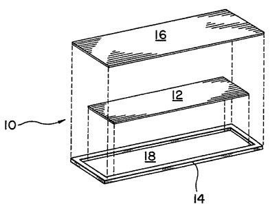
DESCRIPTION OF THE PREFERRED EMBODIMENTS
In the following description the term
"magnetostrictive element" refers to the active magnetic
component (element 12 shown in Fig. 1) that is capable, when
properly activated, of producing a unique ring down signal
in response to an interrogation signal. The term "biasing
element" refers to a control element (element 16 of Fig. 1)
comprised of a magnetic material having a relatively high
coercivity, as compared to the coercivity of the
magnetostrictive element, and which is capable of being
magnetized or demagnetized (i.e., biased or unbiased) to
control the mechanical resonant frequency of the
magnetostrictive element. The term "marker" (generally
indicated by reference numeral 10 in Fig. 1) refers to the
combination of the magnetostrictive element 12 and the
biasing element 16 usually contained within a housing
(element 14 in Fig. 1) and capable of being attached or
associated with merchandise to be protected from theft.
Conventional materials used in the prior art, such
as Metglas 2826 MB (which has a composition of
Feq0Ni38MoqB18) , are used as magnetostrictive elements in
markers without annealing. Annealing such materials tends to
reduce the ring down period, which tends to make such
CA 02492950 1995-04-11
77496-109D
8
materials, if annealed, unsuitable for use in pulsed-field
magnetomechanical EAS systems.
In accordance with the invention, a material that
is rich in cobalt is cut into strips having a uniform fixed
length. The strips are annealed to provide a
magnetostrictive element to be used in fabricating a marker
for a pulsed-field EAS system. A preferred material
according to the invention is an amorphous ribbon of Fe-Co
base alloy, for example, (Feo.5Coo.5) 79Si6B15 or
(Feo_5Coo.5) 79S12B19. It is believed that Fe-Co alloys
containing at least 30% Co by atomic percent will produce
satisfactory results. For example, alloys containing a
combined proportion of iron and cobalt of at least 70%, with
at least 30% cobalt, by atomic percent, and the balance
silicon and boron, are believed to be suitable. The combined
proportion of iron and cobalt in such suitable alloys may
exceed 90%, and it is believed that the maximum combined
proportion of iron and cobalt is only limited by the need to
include sufficient silicon and boron so that the alloy can
be cast in amorphous form.
In a preferred embodiment, the material is cast as
a ribbon that is 0.5 in. wide. The ribbon is cut before
annealing into uniform lengths of 1.56 in. to obtain a
resonant frequency of 58 KHz (corresponding to conventional
pulsed-field detection equipment) upon application of a
conventional dc magnetic biasing field.
Although it is preferred to apply the invention to
a material that has been cast as a ribbon, it is also
possible to use materials in other strip shapes, including
wires, for example. Annealing is carried out in accordance
CA 02492950 2006-09-21
77496-109D
9
with the invention using a strong (saturating) dc magnetic
field applied transversely to the longitudinal axis of the
cut ribbon strips. In the presence of this magnetic field,
the ribbon strips are heated at a temperature of 300
to 540 C for a period of 5 to 60 minutes and then allowed to
cool to room temperature, while maintaining the magnetic
field at least until the material has cooled to below 200 C.
The method by which cooling is performed is not of great
significance as long as the cooling is not too rapid. For
example, it is believed that cooling to room temperature in
less than two minutes will not produce optimum results, and
it is therefore better that cooling not take place simply by
immediate exposure to open air. According to a preferred
technique, the material is cooled by being conveyed through
an unheated but enclosed tube to permit cooling to room
temperature to take place over a period of at least two
minutes.
In some embodiments, the annealing process may
include heating the material at a temperature within the
range of 460 to 540 C for at least 5 minutes.
In further embodiments, the material is then
allowed to cool to room temperature.
Fig. 2 illustrates how the degree of anisotropy
induced by annealing varies with the annealing temperature.
Specifically, the abscissa axis in Fig. 2 is indicative of
the annealing temperature, while the ordinate axis indicates
the degree of anisotropy induced, represented by the
strength of field that would be required to overcome the
CA 02492950 2006-09-21
77496-109D
9a
anisotropy. It is within the contemplation of the present
invention to use annealing temperatures in the range 300 C
up to about 540 C A preferred temperature range would
be 390 C-500 C. Satisfactory results have been obtained with
an annealing temperature of 450 C applied for about 71-~
CA 02492950 1995-04-11
77496-109D
minutes, with cooling to room temperature over a period of
about 7% minutes.
As indicated above, the transverse saturating
magnetic field is maintained during both heating and cool
5 down. The required minimum strength of the transverse
magnetic field applied during annealing and cool down
periods depends on the particular material being treated.
The field should be strong enough to be saturating for the
particular material. For most materials discussed above, the
10 optimum field will be in excess of 500 Oe, and a field of
800 Oe or more will often be necessary to achieve
saturation. Increasing the field strength beyond that
required for saturation is contemplated by the invention but
causes no adverse or beneficial effect.
It is to be noted that the annealing temperature
should not be so high, nor the period of treatment so long,
that more than a minimal amount of crystallization occurs,
since severe crystallization tends to adversely affect ring
down characteristics and imparts an undesirable degree of
brittleness.
Magnetostrictive strips formed in accordance with
the invention can be incorporated in markers that are of
substantially the same construction as conventional
magnetomechanical markers. For example, as shown in FIG. 1,
a marker 10 may be formed in accordance with the present
invention from a magnetostrictive strip 12 which has been
fabricated and treated as described above, a rigid housing
14 formed of a polymer such as polyethylene, and a biasing
element 16. The components making up the marker 10 are
assembled so that the magnetostrictive strip 12 rests within
CA 02492950 1995-04-11
77496-109D
11
a recess 18 of the housing 14, and the biasing element 16 is
held in the housing 14 so as to form a cover for the recess
18. It will be understood that the recess 18 and the
magnetostrictive strip 12 are relatively sized so that the
mechanical resonance of the strip 12, caused by exposure to
a suitable magnetic field, is not mechanically inhibited or
damped by the housing 14 or the biasing element 16.
The length to which the strips are cut is
selected, according to a preferred practice, to produce a
marker that is resonant at 58 KHz, to provide compatibility
with existing detection equipment, while using a
conventional biasing element 16, magnetized at a level used
in conventional magnetomechanical markers.
A marker 10 fabricated in accordance with the
invention may be deactivated in a conventional manner by
degaussing the biasing element 16, so that the marker 10 is
"detuned" and therefore is no longer responsive to the
predetermined interrogation frequency.
As shown in Fig. 3, a marker 10 which incorporates
a magnetostrictive strip formed and treated in accordance
with the present application, has a hysteresis
characteristic indicated by the curve (b) in Fig. 3. It is
to be noted that this characteristic is considerably more
linear and less steep, for relatively small applied magnetic
fields (less than 10 Oe), than the characteristic
illustrated by curve (a), which is exhibited by markers
incorporating conventional magnetostrictive strips, such as
untreated (as cast) strips formed of the alloy Metglas
2826MB marketed by Allied Corporation. As a result, markers
fabricated in accordance with the present invention, when
CA 02492950 1995-04-11
77496-109D
12
deactivated in the magnetomechanical EAS system by
degaussing, generate a much lower harmonic signal in
response to interrogation fields provided by conventional
harmonic detection EAS systems, and are therefore much less
likely to occasion alarms by harmonic systems than a
conventional deactivated magnetostrictive type marker. For
example, a degaussed marker prepared according to the
present invention provides a reduction of at least about
60 dB in harmonic generation, upon exposure to an
interrogation signal, as compared to a marker used in the
conventional harmonic detection EAS system marketed by the
assignee of the present application under the trademark
"AisleKeeper". Although a preferred practice of the
invention achieved a 60 dB reduction in harmonic generation,
it is believed that a reduction in harmonic generation of
about 20 dB would be sufficient to achieve the purpose of
substantially eliminating alarms by harmonic detection EAS
systems in response to deactivated magnetomechanical
markers. It will be understood that the annealing process
serves to smooth the hysteresis characteristic of the
material by reducing nonlinearity therein.
Another advantage of the present invention is that
markers which include magnetostrictive materials formed as
described herein provide more favorable ring down
characteristics than conventional markers using the as-cast
Metglas material referred to above. In particular, Fig. 4
illustrates the superior ring down amplitudes realized with
markers constructed with magnetostrictive strips treated in
accordance with the invention using a range of annealing
temperatures. The curve AO shown in Fig. 4 is illustrative
of amplitudes of the radiated signal obtained from the
CA 02492950 1995-04-11
77496-109D
13
marker immediately after the end of the excitation pulse,
curve Al represents the amplitudes obtained 1 msec after the
end of the pulse, and curve A2 represents the amplitudes
obtained 2 msec after the end of the pulse. The results
shown in Fig. 4 reflect an annealing time of 30 minutes. The
biasing field during interrogation was 5 Oe. Fig. 4
indicates that, over the range of about 410 -510 C, higher
ring down amplitudes are obtained by using higher annealing
temperatures. In general these amplitudes are higher than
the amplitudes provided by the conventional markers using
as-cast Metglas as the magnetostrictive material.
Still another advantage provided by the treatment
disclosed herein is improved consistency in terms of the
resonant frequency of the magnetostrictive strips.
Because of variations in conventional as cast
magnetostrictive materials, cutting the material into strips
of uniform fixed length does not necessarily result in
markers that all have the desired mechanical resonant
frequency. If a marker does not have a resonant frequency
that is sufficiently close to the frequency of the
interrogation field, the marker will not be adequately
excited by the interrogation field. The variations in the
conventional magnetostrictive materials is so great that in
one process it is necessary to measure the resonant
frequency of each strip. If required, the length to which
each strip is cut, after the third strip of a batch, is
adjusted based on the measured resonant frequencies of the
previous three strips. In general, the cut length must be
adjusted often, sometimes for every strip, and generally
after no more than five or six strips. Thus, to compensate
CA 02492950 1995-04-11
77496-109D
14
for the variation in the conventional as cast material, the
conventional processes for manufacturing magnetostrictive
elements includes frequent testing of the resonant frequency
of the cut strips, and then adjusting the length to which
the strips must be cut to obtain the desired resonant
frequency.
However, this invention produces magnetostrictive
elements that exhibit quite consistent resonant frequencies
for a preselected strip length. It is believed that the
greater consistency provided by the present technique
results because the present annealing technique can be
controlled to produce a consistent degree of anisotropy,
whereas the anisotropy of the conventional as cast materials
is a product of the composition resulting from the casting
process, which is inherently subject to variation.
As shown in Fig. 5, in a sample of approximately
150 strips, which were all cut to a uniform length
(1.56 in.), heat treated in accordance with the present
invention (7.5 minutes at 450 C with a saturating transverse
dc magnetic field) and then subjected to a biasing field of
5 oersteds and tested for resonant frequency, nearly all of
the strips had a resonant frequency within a 200 Hz range
around the desired resonant frequency of 58 KHz. This high
degree of consistency provides increased yield, and makes it
unnecessary either to test for variations in resonant
frequency or to compensate for such variations by
periodically adjusting the length of the strips, as is
required when the conventional Metglas material is used.
Yet another advantage provided by the present
invention is that the annealing process disclosed herein
CA 02492950 1995-04-11
77496-109D
produces magnetostrictive strips that are relatively flat as
compared to the conventional as-cast magnetostrictive
strips. For example, Fig. 6A shows a marker 10' in
accordance with the prior art, including an as-cast
5 magnetostrictive strip 12'. As somewhat schematically
illustrated in Fig. 6A, there is a significant degree of
curling in the strip 12' believed to be due to residual
stress. Therefore, the housing 14' provided for a
conventional marker 10' must have a relatively great height
10 H' to accommodate the curled strip 12' without inhibiting
the desired magnetomechanical resonance of the strip. If the
conventional strip is annealed to relieve stress, it has
been found that the unique ring down signal is substantially
reduced.
15 However, as shown in Fig. 6B, the strip 12
prepared in accordance with the present disclosure is
essentially flat, and has only minimal curling, so that the
housing 14 provided in accordance with the present invention
can have a much lower profile than the conventional marker
10' and a height H that is much less than the height H' of
the conventional marker. For example, a housing 14' having
H'=70 to 110 mils may be needed to accommodate a
conventional 1 mil thick Metglas strip 12', but the housing
14 need only have H=5 to 30 mils to accommodate a 1 mil
thick strip 12 treated in accordance with the present
invention. This provides for a thinner marker that is more
conveniently attached to merchandise. Markers that are
thinner or less bulky are much more desirable. The overall
thickness of the housing for a marker is also dependent on
the thickness and uniformity of the material used to form
the housing.
CA 02492950 1995-04-11
77496-109D
16
It should be noted that the annealing process
described herein can also be used to form magnetostrictive
strips into desired curved shapes, rather than the flat
strip shown in Fig. 6B.
Fig. 7 illustrates a pulsed-interrogation EAS
system which uses the magneto-mechanical marker fabricated
in accordance with the invention. The system shown in Fig. 7
includes a synchronizing circuit 200 which controls the
operation of an energizing circuit 201 and a receiving
circuit 202. The synchronizing circuit 200 sends a
synchronizing gate pulse to the energizing circuit 201, and
the synchronizing gate pulse activates the energizing
circuit 201. Upon being activated, the energizing circuit
201 generates and sends an interrogation signal to
interrogating coil 206 for the duration of the synchronizing
pulse. In response to the interrogation signal, the
interrogating coil 206 generates an interrogating magnetic
field, which, in turn, excites the marker 10 into mechanical
resonance.
Upon completion of the pulsed interrogating
signal, the synchronizing circuit 200 sends a gate pulse to
the receiver circuit 202, and the latter gate pulse
activates the circuit 202. During the period that the
circuit 202 is activated, and if a marker is present in the
interrogating magnetic field, such marker will generate in
the receiver coil 207 a signal at the frequency of
mechanical resonance of the marker. This signal is sensed by
the receiver 202, which responds to the sensed signal by
generating a signal to an indicator 203 to generate an alarm
or the like. In short, the receiver circuit 202 is
synchronized with the energizing circuit 201 so that the
CA 02492950 1995-04-11
77496-109D
17
receiver circuit 202 is only active during quiet periods
between the pulses of the pulsed interrogation field.
Various other changes in the foregoing markers and
modifications in the described practices may be introduced
without departing from the invention. The particularly
preferred embodiments of the invention are thus intended in
an illustrative and not limiting sense. The true spirit and
scope of the invention is set forth in the following claims.