Note: Descriptions are shown in the official language in which they were submitted.
CA 02492969 2011-06-01
WELDED WIRE REINFORCEMENT
FOR MODULAR CONCRETE FORMS
FIELD OF THE INVENTION
This invention relates to reinforcements for concrete structures and, more
particularly, to a welded wire reinforcement for modular concrete forms.
BACKGROUND OF THE INVENTION
Insulated concrete walls constructed with pre-fabricated forms are used to
form structural walls both below and above grade. Generally, pre-fabricated
foam blocks,
which are made with two parallel foam panels held together by form ties, are
assembled to
form the desired structure. Reinforcing members, such as rebar, are positioned
inside the
blocks during assembly, and concrete is poured into the foam blocks to
complete the walls.
These walls provide superior strength and efficiency as opposed to the
traditional poured
wall construction with above grade wood frame walls. Insulated concrete walls
provide all
of the features of conventional wood frame construction including doors,
windows, and
decorative architectural features, such as ledges and further provide
additional insulating
capability and increased durability and safety.
The modular concrete forms are simple to position, but the reinforcing
members used to provide internal reinforcement can require extra work to
prepare and
install. Several rebar reinforcements may be required to achieve the desired
level of internal
strength, often necessitating placement of several vertical rebar
reinforcements in the wall.
While horizontally oriented rebar are easily positioned into rebar chairs
provided on the
form ties of the pre-fabricated forms, the vertically oriented rebar
reinforcements often must
be tied into place. For less ordinary forms, such as those used to create
ledges, the
reinforcements must be bent or angled, further increasing labor.
BRIEF SUMMARY OF THE INVENTION
There is, therefore, disclosed a novel welded wire reinforcement for quickly
and efficiently reinforcing a modular concrete form wall system. The welded
wire
reinforcement may include a base bar and several arms extending from the base
bar. The
1
CA 02492969 2011-06-01
welded wire reinforcement can be positioned in a rebar chair of a modular
concrete form to
provide enhanced strength and stability.
In an embodiment, a welded wire reinforcement can include a base bar and
several arms extending downward from the base bar. The arms may include end
pieces that
are positioned in various, selected locations along the arm.
In another embodiment, the welded wire reinforcement is bent to provide
reinforcement to concrete forms used to create ledges. The bent wire
reinforcements can
have a base bar and several arms that are bent to form approximately a 90
angle. The arms
can include end pieces that are positioned at the end of the arms.
Accordingly, it is desirable to provide an improved welded wire
reinforcement for use in modular concrete form wall systems.
It is also desirable to provide an improved bent wire reinforcement for use in
modular concrete form wall systems to enhance the strength of a concrete form
that creates a
ledge.
According to an aspect of the present invention there is provided a one-piece
reinforcement for reinforcing an insulated concrete ledge form having form
ties, the form
ties having at least one rebar chair, the one-piece reinforcement comprising:
a substantially
rigid base including a plurality of rungs for extending into a ledge of the
ledge form; a
plurality of arms connected to the respective rungs, the arms extending
downwardly into the
ledge; at least one inner rail extending transversely of the arms so that the
at least one inner
rail joins the arms; and an outer rail joining the rungs, the outer rail being
positioned
adjacent the terminal end of the rungs, the outer rail being at a different
elevation as
compared to the at least one inner rail, the at least one inner rail being
positionable within
the at least one rebar chair.
According to another aspect of the present invention there is provided an
insulated concrete ledge form in combination with a one-piece reinforcement,
the
combination including: the one-piece reinforcement comprising: a substantially
rigid base
including an inner rail, an outer rail, and a plurality of rungs for extending
into a ledge of the
ledge form; a plurality of arms extending downwardly into the ledge; the outer
rail being
positioned adjacent the terminal end of the plurality of rungs; the inner rail
extending
transversely across the plurality of arms and being positioned at an elevation
which is lower
2
CA 02492969 2011-06-01
than the elevation of the outer rail; and the ledge form comprising: a
substantially straight
concrete form wall; a sloped concrete form wall defining a longitudinal slot
for receiving the
outer rail and defining a plurality of cavities for receiving the rungs; and a
plurality of cross
ties joining the straight form wall and the sloped form wall, the cross ties
each having at
least one rebar chair, the inner rail associating with the at least one rebar
chair.
BRIEF DESCRIPTION OF THE DRAWINGS
These and other inventive features, advantages, and objects will appear from
the following Detailed Description when considered in connection with the
accompanying
drawings in which similar reference characters denote similar elements
throughout the
several views and wherein:
Fig. 1 is a front view of a welded wire reinforcement according to the present
invention;
Fig. 2 is a side view of Fig. 1;
Fig. 3 is a front view of several welded wire reinforcements;
Fig. 4 is a side view of an alternative embodiment of the present invention;
2a
CA 02492969 2005-01-13
Fig. 5 is a side view of an. alternative embodiment of the present invention;
Fig. 6 is a side view of a-bent wire reinforcement in a modular concrete form;
Fig. 7 is a top view the bent wire reinforcement shown in Fig. 6;
Fig. 8 is a side view of the bunt wire reinforcement shown in Fig. 6.
3ET.TEp 33ESCRIFT N
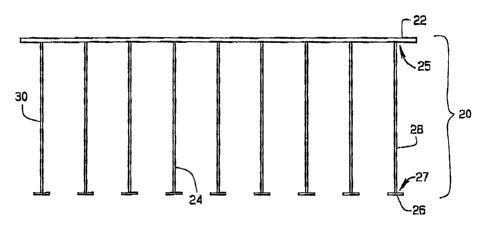
Referring to the drawings in greater detail, Fig. I shows a welded wire
reinforcement 20 constructed in accordance with a preferred embodiment of the
present
invention. The reinforcement 20 includes a substantially rigid base bar 22 and
several
substantially rigid arms 24 preferably welded to the base bar 22.
Substantially rigid means that
the members have sufficient tensile strength to reinforce an intend structure.
The reinforcement
member is operable to reinforce a concrete wall foxmed using modular concrete
form blocks,
including pre-assembled forms and field-assembled forms. While top, bottom,
vertical,
horizontal, and other orientations are referenced in the specification and
claims, it is understood
that. the struchrre of the invention could be utilized in other orientations.
In a preferred embodiment, the base bar 22, as shown in Figs. I and 2, is a
substantially straight and rigid wire having a bar length extending across the
top of the welded
wire reinforcement 20 in a substantially horizontal orientation. The arms 24,
each having a top
end 25, an arm length, and a free end 27, extend downward from the base bar
22, substantially
in the same plane as the base bar. The top ends are attached, preferably
welded, at or adjacent
the top ends. The arms 24 preferably ternainate at their free ends with
substantially
perpendicular end pieces 26, which can be positioned adjacent the free end.
Inoue
embodiment, the end pieces are substantially centered on the arms, so that
they extend an equal
distance on each side of the arms. The arms preferably each extend away from
the base bar at
an arm angle, and preferably, the arm angle is substantially ninety degrees,
so that the arms are
substantially perpendicular to the base bar. The and pieces are preferably
substantially parallel
to the base bar and thus substantially perpendicular to the arms. The arms 24
are similar in
length and shape. The arms are preferably equally spaced along the base bar
22, so that the
arms are positioned between form ties. The base bar 22 extends slightly beyond
the position of
the left most 30 and right-most arms 28. In one embodiment, the base bar 22,
arms 24, and end
KG] ]52 a-z 3
CA 02492969 2005-01-13
pieces 26 are welded together and are all made of substantially rigid wire
with similar
circumference. In another embodiment, the wire has surface texture.
The end pieces 26 are aligned in a substantially straight line to form a
segmented
or discontinuous bottom bar. In one embodiment, the end pieces are offset
relative to the arms,
so that the end pieces are longer on one side of the aims. In another
embodiment, as shown in
Fig. 4, the end piece is located on the a m closer to the base bar 22, with a
portion of the arm
extending downward frora the and piece. In another embodiment, shown in Fig.
5, the ann has
multiple end pieces or cross members positioned along the length of the arm.
The end pieces
along the arm can be evenly spaced or unevenly spaced, depending on the
reinforcement needs
of the arm,, but the end pieces are preferably spaced to align with a set of
rebar chairs defined
by form ties positioned below the base bar during wall construction. Because
some form ties
have upper and lower sets of rebar chairs, the end pieces can be spaced for
alignment with
either or both the upper and lower sets of rebar chairs.
In a preferred embodiment, the welded wire reinforcement 20 is used with
insulated concrete forms 32, sine-lar to those described in U.S. Application
No. 09/691,934,
filed on October 10, 2000, which is fully incorporated herein by reference. As
shown in Figs. 2
and 3, the insulated concrete forms 32 are positioned to form concrete walls-
The forms 32
include ties 34, which extend between opposed, substantially parallel, foam
panels or walls 35,
shown in Fig. 3. The welded wire reinforcement 20 is hung from the ties 34
between the forms
32. The base bar is held in rebar chairs 33, ofthe ties. In one embodiment,
the arms are of a
particular length so that the end pieces are aligned with rebar chairs 47 of a
lower fort' tie.
This could be the upper set 45 or lower set 47 of rebar chairs. Preferably,
the arms are at least
long enough so that the and pieces overlap the base bar of a lower
reinforcement. In one
embodiment, the end pieces would be received in the second, lower set of rebar
chairs while the
first, upper set of rebar chairs are supporting the base bar of the next lower
reinforcement.
Thus, at least the free ends of the arms and preferably the lowest
discontinuous bar are
positioned below the base bar of a lower reinforcement.
In a method of construction for a structure having more than one of the
preferred
foam block forms and more than one of the preferred reinforcements, the end
pieces can be free
between the walls of the form, or the reinforcement can slide left or right,
so that the end pieces
extend through the aligned rebar chairs of a lower tie. The end pieces have a
length that is less
K(}7~s263&-2 4
CA 02492969 2005-01-13
than or equal to the approximate distance between the form ties., so that the
reinforcement can
be inserted from the top of a form with the end pieces and arms passing
between the form ties.
In one embodiment, the welded wire reinforcement 20 is positioned to slightly
overlap, in the horizontal orientation, the position of another reinforcement.
As the desired
number of form block levels, one or more, of the wall are stacked on each
other to form layers,
the reinforcements are put in place, and the next block layer, again one or
more levels, is placed
on top. The next reinforcement is then placed into a rebar chair that is just
to one side of the
previous lower and horizontally adjacent reinforcements. In this fashion, the
reinforcements
are hanging parallel staggered so they are added to the sequentially high form
layers.
Preferably the reinforcements are alternated between sets of substantially
vertically aligned
rebar chairs. Specifically, a first set of rebar chairs support a base bar of
a reinforcement and a
second set of rebar chairs, which are substantially vertically aligned with
the fist set, support a
discontinuous bottom bar of the same reinforcement member. A next lower
reinforcement is
supported by substantially vertically aligned sets of rebar chairs, which are
horizontally offset
from the first and second sets of rebar chairs, and a horizontally adjacent
reinforcement is
supported by substantially vertically aligned sets of rebar chairs, which are
also horizontally
offset from the first and second sets of rebar chairs. When the reinforcements
are placed in the
desired position, concrete is poured into the space between the forms 32.
The reinforcement 20 serves to reinforce the concrete wall created using the
modular concrete forms 32. The positions of the reinforcement can be varied
based on level of
reinforcement necessary for each wail. If more reinforcement is necessary, the
reinforcements
can be positioned and sized to overlap other reinforcements for greater
lengths.
In another embodiment, referring now to Figs. 6 and 7, a bent wire
reinforcement 52 is disclosed. The bent wire reinforcement 52 is operable to
reinforce a
concrete wall with a perpendicular/horizontal ledge for supporting exterior
finishes, such as
bricks or stone, or interior flooring.
As shown in Figs. 6 and 7, the bent reinforcement 52 includes a substantially
horizontal base 66 with several aims 68. The horizontal base 66 is shaped like
a ladder, with
equally spaced rungs 70. The arms 68 depend at approximately a 90 angle from
one edge of
the base 66. The horizontal width of the bent reinforcement 52 is preferably
longer than the
length of the vertical arms 68. The arms are preferably continuous and equally
spaced along
KC-U52635-2 5
CA 02492969 2005-01-13
the base and are positioned similar to the rungs 70, although in an alternate
embodiment the
aims are not equally spaced. An outer side rail 71 joins the outer ends of the
rungs 70, and an
inner side rail 73 joins the arms at 68 and rungs. The two rails 71, 73 are
preferably
continuous, substantially straight, parallel to each other, and perpendicular
to the arms and
S rungs, which are preferably integral and formed by bending a straight wire
to a ledge angle. Tai
a preferred embodiment, the ledge angle is approximately ninety degrees. In an
alternate
embodiment, the arms are welded to the rungs. 7n an alternate embodiment, the
bent
reinforcement could be formed by welding the arms to the horizontal base. The
inner rail 73 is
positioned at a midpoint of the arms, so that the base stays in the desired
orientation which is
preferably horizontal. The inner rail 73 is thus lower than the outer rail and
is preferably. held
in an innermost rebar chair 74. Therefore, when positioned, the rungs are
approximately
horizontal in the form.
In a preferred embodiment, the reinforcement is galvanized or provided with
another coating for corrosion protection. Alternatively, the reinforcement may
be made of a
material other than metal, including plastic.
In a preferred embodiment, the welded wire reinforcement 20 is used with
insulated concrete ledge form 50, shown in Figs. 6 and 7. The ledge form. 50
is reinforced by
the bent wire, reinforcement 52, and includes a straight concrete form wall
62, a sloped concrete
form wall 54, and a plurality of form/cross ties 64. The substantially
straight concrete form wall
62 is substantially vertical. The sloped concrete form wall 54 has a slope 58
that extends
upward and away from the straight form wall 62. The sloped form wall forms
concrete cavities
72 at regularly spaced intervals that extend away from the plane of the sloped
form wail. The
cavities can be positioned between the intervals of the reinforcement rungs
70. The sloped
form wall has a longitudinal slot 56 in the top of the form for receiving the
outer rail 71 of the
reinforcement 52, as shown in Fig. 6. The slot is discontinuous as it
intersects the cavities 72.
The cavities are generally triangular slots open to the gap between the form
walls 62, 54, and
the segments of the slot are open to the cavities.
The cross ties 64 are positioned between, the two form walls 62, 54. The ties
are
positioned between the cavities 72, as shown in Fig. 7. The ties have rows of
equally spaced
and similarly positioned rebar chairs 74 along the tie extending between the
two form walls 62
and 54. The straight concrete form, wall 62 is positioned opposite the sloped
concrete form
xc.nss63s.2 6
CA 02492969 2012-01-12
wall 54. Several cross ties 64 are positioned between the two form walls 62
and 54. A bent
reinforcement 52 is positioned above the cross ties and the slot 56 formed in
the sloped form
wall 54.
In the construction method, the form walls 62 and 54, cross ties 64 and bent
reinforcement 52 are placed in the desired position, concrete is poured into
the space
between the form walls. The concrete fills around the cross ties and bent
reinforcement, and
also fills the slots 56, and cavities 72 formed by the sloped wail form 54.
The concrete
hardens around the rungs, which are in the cavities and the rail which is in
the slot, to form a
wall with the bent reinforcement as reinforcing rebar. Once the wall and ledge
are set, the
decorative brick, or other exterior feature, can be applied to the wall and
ledge.
The welded wire reinforcement 20 according to the present invention
provides a secure mechanism for internally increasing the strength of an
insulated concrete
wall created from modular concrete forms.
Thus, an improved welded wire reinforcement is disclosed which utilizes a
novel configuration of arms and end pieces. This invention allows for superior
reinforcement of an insulated concrete wall system. While preferred
embodiments and
particular applications of this invention have been shown and described, it is
apparent to
those skilled in the art that many other modifications and applications of
this invention are
possible. It is, therefore, to be understood that this invention may be
practiced otherwise
than as specifically described.
7