Note: Descriptions are shown in the official language in which they were submitted.
CA 02493059 2005-O1-21
-1-
METHOD AND DEVICE FOR PRETREATING VIA THE
s CENTRIFUGING OF SAMPLES
to The present invention concerns a method and a device for pretreating
via the centrifuging of blood samples contained in tubes prior to being
introduced into an automatic analysis device.
Generally speaking, so as to analyse them, the tubes of samples are
normally arranged in lines inside containers or sample racks, each containing
1 s several tubes (usually five) axed vertically in a longitudinal vertical
median
plane of the container.
These containers include a base in which a transversal prismatic cavity
is made having a T-shaped section (or round tail).
They are transported inside baskets whose bottoms are equipped with
2o rails having profiles complementary to that of said cavities.
They are introduced into these baskets by being placed side by side so
as to form a line orientated perpendicular to their longitudinal axis and by
moving them in translation in the direction of the line so as to have them
slide
inside the baskets where they are supported and guided by maen of the
2s engaging of the rail in the cavities of the containers.
The transfer of the containers of the baskets where they are located to
the analysis robot is carried out by means of a mobile thrustor in the axis of
the rail and whose step by step movements are ensured by a mechanism
comprising a backgeared motor which drives a pinion which gears with a rack
3o axed perpendicularly to the rail and on which the thrustor is rendered
integral.
CA 02493059 2005-O1-21
-2-
This thrustor is able to move the containers along the rail so as to bring
the final container of the line onto a belt conveyor axed perpendicular to the
rail which feeds the analysis robot.
In the case where it is desired to carry out certain types of analysis,
s such as hemostasis tests on blood samples, it is necessary to centrifuge
these
samples before conducting analysis in the analysis robot.
To this effect, centrifugal machines are used including a rotor with an
axis of vertical rotation to the periphery from which a plurality of boats are
mounted tilting and able to each contain one or several containers of tubes of
samples.
Once the containers are placed in the boat (in a vertical position), the
rotor is driven in rotation. Because of this, under the effect of the
centrifugal
force, the boats are placed horizontally and the samplings contained in the
tubes undergo a centrifuging.
Is Of course, this centrifuging process can only be carried out if the unit
constituted by the rotor, the boats and the containers provided with their
tubes
is correctly balanced.
In fact, if this unit is not correctly balanced, its rotation generates a
vibratory moment which is no longer able to be tolerated beyond a specific
zo threshold.
Owing to this, the centrifugal machine comprises a safety system which
stops the centrifugal machine when this vibratory moment exceeds said
threshold.
So as to take account of this problem, it is therefore necessary to
2s provide prior to each centrifuging stage a balancing stage.
This stage can be carried out manually by adding test tubes in the
incomplete containers. However, this solution involves the continuous
presence of an operator at the centrifuging station. In fact, this balancing
stage
is difficult to make automatic and usually involves access to the containers
3o already placed in the boats of the centrifugal machine which makes it
necessary to intervene concerning the design of the centrifugal machine.
CA 02493059 2005-O1-21
-3-
Thus, the object of the invention is to provide a centrifuging device in
which feeding the centrifugal machine with containers, the balancing of the
centrifugal machine and the transfer of the containers from the centrifugal
machine to the analysis robot are carried out automatically with the aid of
s relatively simple reliable and inexpensive elements.
To this effect, the invention provides a method including the following
operational phases
- the detection of the presence of tubes inside the containers at the
time the latter are transported to the centrifugal machine ;
to - the detection of a foreseeable lack of balance of the centrifugal
machine and when this detection reveals to the presence of this lack
of balance due to the presence of an incomplete container ;
- the simulation of the load of the centrifugal machine incorporating
the incomplete container ;
is - the selection of a balancing container according to the number of
tubes missing in the incomplete container or an odd number of
containers ;
- the determination of the boat of the centrifugal machine inside
which the balancing container needs to be placed so as to obtain a
2o good balancing of the load ;
- the placing of this container in said boat in the place of the samples
container which should to be already there, thus provoking a shift in
the order for introducing the sample containers in the centrifugal
machine ;
2s - the replacing of the balancing container onto its storage area during
the transfer of the sampling containers to the robot once centrifuging
has been carried out.
As regards the selection of the balancing containers, the invention
simplifies this operation by being based on the fact that the centrifugal
3o machine tolerates a lack of balance slightly exceeding the lack of balance
brought about by the absence of one tube out of five normally present in the
CA 02493059 2005-O1-21
-4-
container. Because of this, it is enough to provide only two types of
balancing
containers respectively corresponding to one container containing two tubes
and one container containing four tubes so as to compensate all the possible
lacks of balance.
s One embodiment of the invention is described hereafter and is given by
way of non-restrictive example with reference to the accompanying drawings
on which
Figure 1 is a diagrammatic perspective view of a tube container ;
Figure 2 is a diagrammatic vertical section of a centrifugal machine ;
Figures 3 to 6 are top views of a centrifuging device according to the
invention at various stages for the functioning of said device ;
Figures 7 and 8 are diagrammatic axial sections illustrating the
operating principle of the device for feeding the centrifugal machine
associated with the detector detecting the presence of tubes in the containers
;
Figures 9 and 10 are flow charts of the programme used to balance the
centrifugal machine.
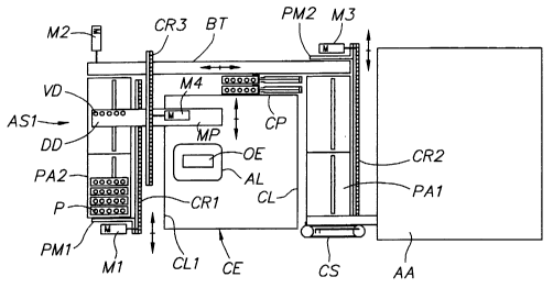
In this example, the device of the invention is intended to pretreat by
means of centrifuging the samples contained in tubes T placed in containers P,
such as the one shown on figure 1 prior to the introduction of these
containers
2o P one by one into an analysis robot AA.
This analysis robot AA may comprise, as described in the patent FR No
97 07 751 filed in the name of the Applicant, a pipetting area in which the
tubes of samples T, placed in their containers P and previously identified,
are
successively brought and above which a pipette head moves.
2s During the process preceding the phase for carrying out tests in the
analysis robot AA, the containers P containing the tubes (sealed) of samples
(for example blood samples) are placed in the boats NA of a centrifugal
machine CE, such as the one illustrated on figure 2 where they are subjected
to
centrifuging. Throughout this process, the tubes T are kept inside the
3o containers so as to avoid being handled.
CA 02493059 2005-O1-21
-$-
On leaving the centrifugal machine CE, the containers containing the
tubes are brought into specially designed baskets placed in a container
distributor DP1 which equips the feeding station PA1 of the containers P at
the
analysis robot AA.
s The containers P used may consist of the container P shown on figure 1
and having a general parallelepiped shape with bevelled vertical edges. This
container comprises a base E provided with a ribbing delimiting a transversal
prismatic cavity CP having an approximately C-shaped section or round tail
and intended to cooperate with a guiding rail RG having a complementary T-
to shaped section.
This rail RG is provided at the bottom of the baskets PA1, PAZ and in
the transfer areas in which the containers P are moved in translation
perpendicular to their axis of symmetry.
The upper portion of the container P here comprises five vertical
~5 cylindrical alveoles A1 to AS opened at the level of the upper face of the
container and intended to receive five respective tubes T.
Figures 3 to 7 show the path followed by the containers P in the
pretreating device from a station PAZ for feeding this device in which the
containers P are placed in baskets as far as the feeding station of the
analysis
2o robot where these containers are again brought together in a basket PAl
associated with a one-by-one container distributor DP1.
In these figures, the centrifugal machine CE has been shown in the
shape of a rectangular block inside which an extraction feeding area AL is
also
represented by a block in which the containers can be successively introduced
2s or extracted by means of a grasping mechanism MP.
The feeding station PAZ is placed along one lateral side CL1 of the
centrifugal machine CE situated opposite the feeding station PA1 of the robot
AA, these two stations PAI, PAZ being approximately adjacent to the front
side CA of the centrifugal machine CE.
CA 02493059 2005-O1-21
-6-
It is equipped with a mobile thrustor PM1 in translation along the lateral
side CL1 and driven by a device introducing a motor Ml which drives a pinion
geared onto a rack CRI.
The purpose of this thrustor PMl is to extract the containers P contained
s in the baskets situated in the feed station PAI, to bring them into a
storage area
AS1 adjacent to a belt conveyor BT driven by a motor M2 which runs parallel
to the rear side CP of the centrifugal machine CE and thus perpendicular to
the
displacement axis of the thrustor PM1.
This belt conveyor BT transports one by one the containers P pushed by
io the thrustor PMl to a grasping area in which the grasping mechanism MP
takes them so as to bring them to the feeding area AL of the centrifugal
machine CE where they axe placed in the boats NA. The belt conveyor BT
further allows the transportation of the thrustors P extracted from the
centrifugal machine CE by the grasping means to a transport area situated on
is the lateral side CL2 of the centrifugal machine adjacent to the feeding
station
PA2 of the robot AA. This transport area introduces a thrustor PM2 able to
move perpendicular to the direction of running off of the belt conveyor BT so
as to transfer via a translation movement the containers P brought by the belt
conveyor BT into the basket equipping the feeding station PA1. To this effect,
2o the thrustor PM2 is activated by means of a mechanism introducing a gear
driven in rotation by a motor M3 which gears with a rack CR2.
The distribution of the containers P contained in the basket of the
feeding station PA1 inside the analysis robot AA is effected with the aid of
an
endless belt CS mounted on rollers axed vertically, one of said rollers being
2s driven in rotation by a motor. This belt CS, placed at the end of the
basket
parallel to the containers P, bears a drive dog able to be geared on the
extremity of the containers P and situated opposite the intake opening of the
analysis robot AA.
As shown on figure 3, the centrifugal machine CE could
3o advantageously include a rotor RV with a vertical axis driven by an
electric
motor M4 and comprising a rotary support element PS provided with a
CA 02493059 2005-O1-21
_7_
plurality of pairs of coaxial journals TC on each of which it is possible to
suspend oscillating boats NA designed to receive the containers P at the rate
of
one or several containers per boat. In this example, the means to ensure
suspension and allow rotation of the boats NA consists of half bearing DP
s open towards the bottom in which the journals TC are engaged so that these
boats NA can be easily extracted by lifting them up.
The whole of this mechanism is housed inside a box closed at its upper
portion by a plate PL which includes at the level of said feed zone an orifice
OE used for extracting the boats NA.
To this effect, the centrifugal machine includes an extraction
mechanism consisting of a support element mounted on the rod T1 of a jack
placed below the orifice OE and intended to lift up the boats NA up to a level
situated above the plate PL so that the containers P contained in the boats NA
can be picked up by the grasping means MP, or conversely these grasping
15 means MP can be laid with new containers P.
At the time they are lifted up, the boats NA can be rendered integral
temporarily on the extremity of the support element with the aid of permanent
magnets.
As mentioned previously, the aim of the invention is to automatically
2o resolve the problems of the balancing of loads of the rotor so as to obtain
a
fully automated functioning of centrifuging, as well as the various transfers
of
the containers to the feeding station of the robot.
To this effect, the invention provides a device for detecting the presence
of tubes inside the containers during their path from the feeding station PAZ
up
2s to the belt conveyor BT.
This detection device DD here includes a row of detection jacks VD
axed perpendicular to the displacement axis of the containers P and mounted
on a structure moving in translation above the containers P from the station
PAZ as far as the belt conveyor BT. (The detection of the presence of a tube
3o being obtained when the rod of the jack stopped on the tube is unable to
carry
out a complete travel).
CA 02493059 2005-O1-21
_g_
Driven is provided by a mechanism introducing a motor M4 driving a
pinion which gears on a rack CR3.
The mechanism for picking up and transporting the containers between
the belt conveyor BT and the feeding area AL of the centrifugal machine CE is
s integral with the structure bearing the detection jacks VD.
In accordance with the invention, this device introduces a processor
which controls all the motors Ml to M4 of the belt distributor CS, as well as
the functioning of the centrifugal machine so as to obtain the following
operating sequence.
Initially, a basket containing the containers (in this instance four) is
placed in the feeding station PA2, the thrustor PMl being in a pushed back
position (fig. 3).
The thrustor PMl is then activated and pushes back the four containers
P into a storage area adjacent to the belt conveyor BT (fig. 4). The presence
15 detection device DD then moves above the containers P and, for each
container P, detects the presence or absence of the tubes T contained in this
container P. The information relating to these presences or absences is sent
to
the processor.
At the end of detection, the presence detector and accordingly the
2o grasping mechanism are arranged above the belt conveyor BT (fig. 4).
This processor conducts simulations by means of the information
originating from the device DD so as to be able to allocate each of the
thrustors PM to a boat of the centrifugal machine CE so as to balance the
latter. In the case where the processor observes a lack of balance, it is able
to
2s replace one of the thrustors with a balancing thrustor PE1, PE2.
As mentioned previously, in the case where the tolerance permitted by
the centrifugal machine CE is one tube per container, it is possible to only
use
two different types of balancing containers PE1, PE2 corresponding
respectively to one container including four tubes and one container including
3o two tubes.
CA 02493059 2005-O1-21
_9_
These two containers PE1, PE2 are placed on a storage area of the plate
of the centrifugal machine and pushed by two respective jacks to a location
accessible by the grasping mechanism MP (fig. 8).
Once the processor has allocated to each of the boats NA a container P
s (possibly a balancing container), the thrustor PMI pushes the containers P
one
by one onto the belt conveyor BT. Each container is then picked up by the
grasping mechanism MP which transports it and introduces it into the boat NA
located above the orifice OE (figs 5 and 7).
Once a thrustor PM has been introduced into a boat NA, the boat NA is
lowered again by the jack V so as to be again suspended from the journals TC
of the support element PS. The rotor RV then rotates so as to bring the next
boat NA determined by the processor (virtual rotor) to the right of the
orifice
OE. The jack V can then lift up this boat NA so as to have it pass through the
orifice OE up to a position in which it is able to receive a container P which
1s has been allocated to it by the processor.
Once all the boats NA are provided with containers P, the centrifugal
machine CE carnes out a centrifuging stage.
Via an inverse process, the centrifugal machine CE is unloaded. To this
effect, the boats NA are successively lifted up by the jack V so as to present
2o the containers) P they contain at the grasping mechanism MP. This
mechanism brings the container P back onto the conveyor belt BT or, when it
involves a balancing container, onto the storage area.
The containers P brought back onto the belt conveyor BT are brought
one by one to the right of the thrustor PM2 which pushes them back onto the
2s basket PA1 situated in the feeding area of the robot AA. These containers P
are
then moved into the robot by the belt CS.
Figures 9 and 10 show the various stages carried out by the processor
so as to determine the positioning of the containers inside the centrifugal
machine.
3o So as to determine this positioning, the processor implements the
positioning algorithm shown on figure 9 which includes first of all the
CA 02493059 2005-O1-21
-10-
construction of a virtual rotor (block B1) containing the containers P in
which
the presence of the tubes T has been detected by the presence detectors,
followed by the calculation of the optimum arrangement (block B2). The
processor next calculates the unbalance of this arrangement and determines if
s this unbalance is correct or not (for example if it is less than 20 grams)
(block
Bg).
If the unbalance is correct, the balancing treatment ends (block B4).
On the other hand, if the unbalance exceeds the fixed limit (here 20
grams), the processor determines if the centrifugal machine is full (block
BS).
If there is a place available, the processor adds a balancing container to
the virtual rotor (block B6) and then it calculates the optimum arrangement
(block B~). If the new unbalance of the rotor is correct (less than the limit)
(block Bg), the balancing treatment ends. (block B4). If the unbalance of the
rotor exceeds the limit (block Bg), the processor eliminates the balancing
~s container (block B9) and then determines if there is a container able to be
eliminated (block Blo). If this is not the case, the processor ends the
treatment
and triggers an error signal signifying that balancing is impossible (block
Bl).
If there is a container able to be eliminated (block Boo), the processor
eliminates the final container of the virtual rotor (block B12) and calculates
the
20 optimum arrangement (block B13)
If the unbalance of the rotor is outside the limit (block B14), the
processor returns to the stage for adding a balancing container (block B6). On
the other hand, if the unbalance is correct, the balancing treatment ends
(block
B4).
2s If, during finding if the centrifugal machine is full (block BS) the
virtual
rotor is full, the processor moves directly to the determination stage if
there
exists a container able to be eliminated (block Blo).
The stage for calculating the optimum arrangement provided on the
algorithm of figure 9 (blocks B2 and B~) can be carried out in accordance with
3o the algorithm of figure 10 which successively includes the calculation of
the
CA 02493059 2005-O1-21
-11-
unbalance of the rotor (block B25), the determination of the optimum rotor, as
well as the optimum unbalance (block B26).
The processor then determines if the unbalance is lower than a
predetermined threshold (block B2~) and lower than the optimum unbalance
s (block BZg).
If the unbalance is lower than the threshold, the search for the optimum
rotor ends (block B2g). If the unbalance is lower than the optimum unbalance
(block BZg), the system determines the optimum rotor and the optimum
unbalance (block B29) and if there still exists a possible permutation (block
to B3o). If the unbalance were lower than the optimum unbalance at the block
B2g, the system passes directly to the block B3o.
If no permutation is possible, this means that all the permutations have
been scanned and the search for the optimum rotor ends (block B2g). If a
permutation is possible, the system carries out the permutation (block B31)
and
is then calculates the unbalance of the rotor (bock B32~ and returns to the
block
B2~ for a new sequence.