Note: Descriptions are shown in the official language in which they were submitted.
CA 02493380 2005-O1-11
WO 2004/007906 PCT/US2003/021626
A SUBTERRANEAN DRAINAGE PATTERN AND A METHOD FOR DRILLING RAMPED WELLBORES
TECHNICAL FIELh OF THE IIV~IENTIOIyT
The present invention relates generally to the recovery of subterranean
deposits, and more particularly to a method and system for accessing
subterranean
deposits from the surface.
BACKGR~UNI~ OF THE INVENTION
Subterranean deposits of coal typically contain substantial quantities of
entrained methane gas. There are many uses for methane gas extracted from the
subterranean deposits. Substantial obstacles, however, have frustrated more
extensive
development and use of methane gas deposits in coal seams. A common problem in
producing methane gas from coal seams may be vertical separation of multiple
thin
layers of coal within a coal seam. Although coal seams may extend over large
areas
of up to several thousand acres, the depth of the multiple layers in the coal
seam may
vary from very shallow to very deep. Vertical wells drilled into the coal
deposits for
obtaining methane gas can only drain a fairly small radius around the coal
deposits.
Further, coal deposits are not amenable to pressure fracturing and other
methods often
used for increasing gas production from conventional rock formations. As a
result,
production of gas may be limited in volume. Additionally, coal seams are often
associated with subterranean water, wluch must be drained from the coal seam
in
order to produce the methane.
SUMMARY OF THE INVENTION
The present invention provides an improved method and system for accessing
subterranean deposits from the surface that substantially eliminates or
reduces the
disadvantages and problems associated with previous systems and methods. In
particular, the present invention provides an articulated well with a drainage
pattern
that provides access to a large subterranean area from the surface.
In accordance with one embodiment of the present invention, a subterranean
drainage pattern for accessing a subterranean zone includes a main well bore
CA 02493380 2005-O1-11
WO 2004/007906 PCT/US2003/021626
extending from a surface well bore, located at a first end of the area, to a
second end
of the area. A first plurality of lateral well bores extend in spaced apart
relation to
each other from the main well bore to the periphery of the area on a first
side portion
of the main well bore. A second plurality of lateral well bores extend in
spaced apart
relation to each other from the main well bore to a periphery of the area on a
second,
opposite side portion of the main well bore. A first plurality of ramping well
bores
extend in spaced apart relation to each other from the main well bore toward a
boundary of the subterranean zone.
Embodiments of the present invention may have some, all, or none of the
following advantages. In particular embodiments, an improved multi-plane
drainage
pattern may include upwardly ramping well bores and/or downwardly ramping well
bores to maximize access to a subterranean zone. Upwardly ramping well bores
may
extend upwardly from the main well bore to maximize access to the upper
portion of a
single, thick layer of subterranean deposits. Alternatively or additionally,
upwardly
ramping well bores may extend upwardly from the main well bore to maximize
access
to multiple layers of subterranean deposits. Similarly, downwardly ramping
well
bores may extend downwardly from the main well bore to maximize access to a
lower
portion of a single, thick layer of subterranean deposits andlor to maximize
access to
multiple layers of subterranean deposits separated by impermeable or
substantially
impermeable material. In particular embodiments, mufti-plane drainage pattern
may
include lateral well bores in addition to upwardly ramping well bores. Lateral
well
bores may extend from opposite sides of the main well bore in a substantially
horizontal plane to provide greater access to an area of the subterranean
zone. A
further technical advantage may include maximizing the area covered by the
drainage
pattern both horizontally and vertically while reducing the number of times a
drill
string changes direction while drilling a bore hole. Consequently,
disadvantages
arising from differences in pressure head caused by vertical curves in a well
bore may
be substantially reduced.
Other technical advantages of the present invention will be readily apparent
to
one skilled in the art from the figures, description, and claims, included
herein.
CA 02493380 2005-O1-11
WO 2004/007906 PCT/US2003/021626
J
ERIEF DESCRIPTION OF THE DRAWINGS
For a more complete understaalding of the present invention and its
advantages, reference is now made to the following description taken in
conjunction
with the accompanying drawings, wherein like numerals represent like parts, in
which:
FIGURE 1 is a cross-sectional diagram illustrating the drilling of an example
dual well system for accessing a subterranean zone from the surface;
FIGURE 2 is a cross-sectional diagram illustrating the drilling of an example
dual well system for accessing a subterranean zone from the surface;
FIGURE 3 is a cross-sectional diagram illustrating the use of an example dual
well system for the production of fluids;
FIGURE 4 is a top plan diagram illustrating an example pinnate drainage
pattern for accessing deposits in a subterranean zone;
FIGURE 5 is a top plan diagram illustrating an example pinnate drainage
pattern for accessing deposits in a subterranean zone;
FIGURE 6 is a top plan diagram illustrating an example quadrilateral piimate
drainage pattern for accessing deposits in a subterranean zone;
FIGURE 7 is a cross-sectional diagram illustrating an example mufti-plane
well bore pattern for accessing a single, thick layer of subterranean
deposits;
FIGURE 8 is a cross-sectional diagram illustrating an example mufti-plane
well bore pattern for accessing multiple layers of subterranean deposits;
FIGURE 9 is an isometric diagram illustrating an example mufti-plane well
bore pattern for accessing deposits in a subterranean zone; and
FIGURE 10 is a flow diagram illustrating an example method for producing
gas from a subterranean zone.
DETAILED DESCRIPTION OF THE INVENTION
FIGURE 1 is a cross-sectional diagram illustrating the drilling of an example
dual well system for accessing a subterranean zone from the surface. In one
embodiment, the subterranean zone may be a coal seam. It will be understood
that
other subterranean zones can be similarly accessed using the dual well system
of the
CA 02493380 2005-O1-11
WO 2004/007906 PCT/US2003/021626
n
~h
present invention to remove and/or produce water, hydrocarbons and other
fluids in
the zone and to treat nunerals in the zone prior to mining operations.
In addition to production, the dual well system rnay be used for environmental
remediation purposes to treat or recover underground contaminants posing a
danger to
the environment. Remediation may include neutralizing leaching, recovery,
dissolving, oxidation, reduction, or other suitable process. For example, the
dual well
system may be used to inject a treatment solution into a contaminated coal
seam or
surrounding area. The treatment solution may comprise either a liquid or a
gas.
Where treatment includes biological processes or biological mediated processes
(including bioremediation), the treatment solution may include bacteria,
nutrients, or
other materials which may affect the metabolism, respiration, or other
processes of
bacteria or other organisms. The dual well system may also be used to recover
byproducts from the contaminated coal seam or surrounding area or to strip
recoverable product from the coal seam.
Dual well system may also be used for the sequestration of gaseous emissions
from internal combustion engines, or other materials for which disposal by
underground sequestration may be appropriate. For example; certain underground
formations such as coal have high absorption affinities for carbon dioxide,
sulfur
oxides, nitrogen oxides, and/or other gases or other materials that may
comprise
regulated substances or pollutants. Thus, materials such as carbon dioxide may
be
sequestered in a sequestration zone such as a coal seam. Well bore patterns
may be
drilled proximate to the sequestration zone (adjacent to and/or within the
zone) and
the materials injected into the well bore patterns. In a particular
embodiment, the
materials comprise gases such as carbon dioxide that may first be entrained in
water
or another liquid. The liquid may act as a carrier medium, and the gas/carrier
medium
mixture pumped into the well bore patterns with the aid of a surface pump. The
pinnate pattern may provide for an increased surface area of the underground
injection
zone, thus providing for more efficient and effective sequestration.
Refernng to FIGURE 1, a substantially vertical well bore 12 extends from the
surface 14 to a target layer subterranean zone 15. The substantially vertical
well bore
12 intersects, penetrates and continues below the subterranean zone 15. The
CA 02493380 2005-O1-11
WO 2004/007906 PCT/US2003/021626
substantially vertical well bore may be lined with a suitable well casing 16
that
terminates at or above the level of the coal seam or other subterranean zone
15.
The substantially vertical well bore 12 may be logged either during or after
drilling W order to locate the exact vertical depth of the target subterranean
zone 15.
As a result, subterranean zone 15 is not missed in subsequent drilling
operations, and
techniques used to locate the zone 15 while drilling need not be employed. An
enlarged diameter cavity 20 may be formed in the substantially vertical well
bore 12
at a level of or in the subterranean zone 15. As described in more detail
below, the
enlarged diameter cavity 20 provides a junction for intersection of the
substantially
vertical well bore 12 by an articulated well bore 30 used to form a drainage
pattern in
the subterranean zone 15. However, drilling techniques may also be used that
eliminate the need for an enlarged cavity in order to intersect vertical well
bore 12.
The enlarged diameter cavity 20 also may provide a collection point for fluids
drained
from the subterranean zone 15 during production operations.
In one embodiment, the enlarged diameter cavity 20 has a radius of
approximately eight feet and a vertical dimension that equals or exceeds the
vertical
dimension of the subterranean zone 15; however, any appropriate radius may be
used
(and the cavity many not be cylindrical) and the vertical dimension of the
cavity many
not extend out of subterranean zone 15. The enlarged diameter cavity 20 may be
formed using suitable under-reaming techniques and equipment. A vertical
portion of
the substantially vertical well bore 12 may continue below the enlarged
diameter
cavity 20 to form a sump 22 for the cavity 20.
An articulated well bore 30 extends from the surface 14 to the enlarged
diameter cavity 20 of the substantially vertical well bore 12. The articulated
well bore
30 may include a substantially vertical portion 32, a substantially horizontal
portion
34, and a curved or radiused portion 36 interconnecting the vertical and
horizontal
portions 32 and 34. In one embodiment, the horizontal portion 34 lies
substantially in
the horizontal plane of subterranean zone 15 and intersects the large diameter
cavity
20 of the substantially vertical well bore 12. One slcilled in the art may
recognize,
however, that the substantially horizontal portion 34 need not be precisely
horizontal
where the subterranean zone itself is not precisely horizontal. Rather,
substantially
CA 02493380 2005-O1-11
WO 2004/007906 PCT/US2003/021626
horizontal portion 34: merely implies that the portion 34 is in conformance
with the
general shape of subterranean zone 15. Thus, if subterranean zone 15 is
inclined,
substantially horizontal portion 34 may also be inclined in conformance with
the
plane of the subterranean zone 15.
Articulated well bore 30 is offset a sufficient distance from the
substantially
vertical well bore 12 at the surface 14 to permit the large radius curved
section 36 and
any desired horizontal section 34 to be drilled before intersecting the
enlarged
diameter cavity 20. In one embodiment, the articulated well bore 30 is offset
a
distance of about three hundred feet from the substantially vertical well bore
12 to
provide the curved portion 36 with a radius of one hundred to one hundred and
fifty
feet. This spacing minimizes the radius of the curved portion 36 to reduce
friction in
the bore 30 during drilling operations. As a result, reach of the articulated
drill string
drilled through the articulated well bore 30 is maximized. ~ne skilled in the
art may
recognize, however, that a distance of three hundred feet and a radius of one
hundred
to one hundred and fifty feet is merely exemplary. The radius of curved
portion 36
may be any other suitable radius that allows articulated well bore to curve
and access
subterranean zone 15. Accordingly, the distance between the articulated well
bore 30
and the substantially vertical well bore 12 may be any suitable distance
allowing the
articulated well bore 30 to intersect the enlarge diameter cavity 20.
Articulated well bore 30 may be drilled using articulated drill string 40 that
includes a suitable down-hole motor and bit 42. A measurement while drilling
(MWD) device 44 may be included in the articulated drill string 40 for
controlling the
orientation and direction of the well bore drilled by the motor and bit 42.
Any portion
of the articulated well bore 30 may be lined with a suitable casing 38.
After the enlarged diameter cavity 20 has-been successfully intersected by the
articulated well bore 30, drilling is continued through the cavity 20 using
the
articulated drill string 40 and appropriate horizontal drilling apparatus to
provide a
drainage pattern in the subterranean zone 15 that initiates from cavity 20 as
main well
bore 50. Main well bore 50 and other such well bores may include sloped,
undulating, or other inclinations of the coal seam or other subterranean zone
15.
Although FIGURE 1 shows only a beginning portion of the main well bore 50,
main
CA 02493380 2005-O1-11
WO 2004/007906 PCT/US2003/021626
well bore 50 -may extend further into subterranean zone 15. Additional well
bores
may extend from the main well bore 50 to form a drainage pattern. Duw.-ing
this
operation, gamma ray logging tools and conventional le~JD devices may be
employed to control and direct the orientation of the drill bit to retain the
main well
bore 50 within the confines of the subterranean zone 15 and to provide
substantial
coverage of a desired area within the subterranean zone 15. Various types of
drainage
patterns are described in more detail below in connection with FIGURES 4-14.
During the process of drilling the drainage pattern 50, drilling fluid or
"mud"
may be pumped down the articulated drill string 40 and circulated out of the
drill
string 40 in the vicinity of the bit 42. Mud may be used to scour the
formation and to
remove formation cuttings. The cuttings are then entrained in the drilling
fluid which
circulates up through the annulus between the drill string 40 and the well
bore walls
until it reaches the surface 14. Cuttings may be removed from the drilling
fluid and
the fluid may then be recirculated. This conventional drilling operation
produces a
standard column of drilling fluid having a vertical height equal to the depth
of the
well bore 30 and produces a hydrostatic pressure on the well bore
corresponding to
the well bore depth. Because coal seams tend to be porous and fractured, they
may be
unable to sustain such hydrostatic pressure, even if formation water is also
present in
the coal seam. Accordingly, if the full hydrostatic pressure is allowed to act
on the
coal seam, the result may be loss of drilling fluid and entrained cuttings
into the
formation. Such a circumstance is referred to as an "over-balanced" drilling
operation
in which the hydrostatic fluid pressure in the well bore exceeds the ability
of the
formation to withstand the pressure. Loss of drilling fluids in cuttings into
the
formation not only is expensive in terms of the lost drilling fluids, which
must be
made up, but it tends to plug the pores in the coal seam, which are needed to
drain the
coal seam of gas and water.
To prevent over balance drilling conditions during formation of drainage
pattern that may include main well bore 50, air compressors 60 may be provided
to
circulate compressed air down the substantially vertical well bore 12 and back
up
through the articulated well bore 30. The circulated air will admix with the
drilling
fluids in the annulus around the articulated drill string 40 and create
bubbles
CA 02493380 2005-O1-11
WO 2004/007906 PCT/US2003/021626
throughout the column of drilling fluid. This has the effect of lightening the
hydrostatic pressure of the drilling fluid and reducing the down-hole pressure
sufficiently such that drilling conditions do not become over-balanced.
Aeration of
the drilling fluid may reduce down-hole pressure to approximately 150-200
pounds
per square inch (psi), in particular embodiments. Accordingly, low-pressure
coal
seams and other subterranean zones can be drilling without substantial loss of
drilling
fluid and contamination of the zone by the drilling fluid.
Foam, which may include compressed air mixed with water, may be circulated
down through the articulated drill string 40 along with the drilling mud in
order to
aerate the drilling fluid in the annulus, if desired, as the drainage pattern
is being
drilled. Drilling of the drainage pattern with the use of an air hammer bit or
an air-
powered down-hole motor will also supply compressed air or foam to the
drilling
fluid. In this case, the compressed air or foam, which is used to power the
bit or
down-hole motor, exits in the vicinity of the drill bit 42. However, the
larger volume
of air which can be circulated down the substantially vertical well bore 12,
permits
greater aeration of the drilling fluid than generally is possible by air
supplied through
the articulated drill string 40.
FIGURE 2 is a cross-sectional diagram illustrating the drilling of an example
dual well system for accessing a subterranean zone from the surface. In this
embodiment, the substantially vertical well bore 12, enlarged diameter cavity
20 and
articulated well bore 32 may be positioned and formed as previously described
in
connection with the FIGURE 1.
Referring to FIGURE 2, after intersection of the enlarged diameter cavity 20
by the articulated well bore 30, a pump 52 is installed in the enlarged
diameter cavity
20 to pump drilling fluid and cuttings to the surface 14 through the
substantially
vertical well bore 12. This eliminates the variable friction of air and fluid
returning
up the articulated well bore 30 and reduces down-hole pressure to any desired
value.
Accordingly, coal seams and other subterranean zones having ultra low
pressures
below 150 psi can be accessed from the surface 14. Additionally, the risk of
combining air and methane in the well is eliminated.
CA 02493380 2005-O1-11
WO 2004/007906 PCT/US2003/021626
r,
FIGURE 3 is a cross-sectional diagram illustrating the use of an example dual
well system for the production of fluids. W this embodiment, after the
substantially
veutical and articulated well bores 12 and 30 as well as desired drainage
pattern have
been drilled, the articulated drill string 40 is removed from the auticulated
well bore
30 and the articulated well bore is capped. A down hole pump 80 is disposed in
the
substantially vertical well bore 12 in the enlarged diameter cavity 20. The
enlarged
cavity 20 provides a reservoir for accumulated fluids allowing intermittent
pumping
without adverse effects of a hydrostatic head caused by accumulated fluids in
the
vertical well bore 12.
The down hole pump 140 is connected to the surface 14 via a tubing string 82
and may be powered by sucker rods 84 extending down through the well bore 12
of
the tubing. The sucker rods 84 are reciprocated by a suitable surface mounted
apparatus, such as a powered walking beam 86 to operate the down hole pump 80.
The down hole pump 80 may be used to remove water and entrained fines from the
subterranean zone 15 via the drainage pattern. Alternatively or additionally,
down
hole pump 80 may be used in remediation processes to inject treatment solution
into a
contaminated area or in sequestration processes to inject gaseous emissions
entrained
in a carrier medium. Once the water is removed to the surface, it may be
treated to
remove methane or other gas dissolved in the water and entrained fines. After
sufficient water has been removed from the subterranean, gas may be allowed to
flow
to the surface 14 through the annulus of the substantially vertical well bore
12 around
the tubing string 82 and removed via piping attached to a wellhead apparatus.
At the
surface 14, the gas may be treated, compressed and pumped through a pipeline
for use
as a fuel in a conventional manner. The down hole pump 80 may be operated
continuously or as needed to remove water drained from the coal seam into the
enlarged diameter cavity 20.
FIGURES 4-6 are top plan diagrams illustrating example pinnate drainage
patterns for accessing deposits in a subterranean zone. In the example
embodiments,
the drainage patterns may comprise pinnate patterns that have a main drainage
well
bore 104 with generally symmetrically arranged and appropriately spaced
lateral well
bores 110 extending from each side of the main drainage well bore. The pinnate
CA 02493380 2005-O1-11
WO 2004/007906 PCT/US2003/021626
pattern approximates the pattern of veins in a leaf or the design of a feather
in that it
has similar, substantially parallel, lateral drainage bores 110 arranged in
substantially
equal and parallel spacing on opposite sides of an axis. The pinnate drainage
pattern
with its main drainage well bore 104 and generally symmetrically arranged and
5 appropriately spaced lateral drainage bores 110 on each side provides a
uniform
pattern for draining fluids from a coal seam or other subterranean formation.
As
described in more detail below, the pinnate pattern may provide substantially
uniform
coverage of a square, other quadrilateral, or grid area and may be alig~led
with
longwall mining panels for preparing the subterranean 15 for mining
operations. It
10 will be understood that other suitable drainage patterns may be used in
accordance
with the present invention.
The pinnate and other suitable drainage patterns drilled from the surface
provide surface access to subterranean formations. The drainage pattern may be
used
to uniformly remove and/or insert fluids or otherwise manipulate a
subterranean
deposit. In non-coal applications, the drainage pattern may be used initiating
in-situ
burns, "huff puff' steam operations for heavy crude oil, and the removal of
hydrocarbons from low porosity reservoirs.
FIGURE 4 is a top plan diagram illustrating an example pinnate drainage
pattern 100 for accessing deposits in a subterranean zone 15 in accordance
with one
embodiment of the present invention. In this embodiment, the pinnate drainage
pattern 100 provides access to a substantially square area 102 of a
subterranean zone.
A number of the pinnate patterns 100 may be used together to provide uniform
access
to a large subterranean region.
The enlarged diameter cavity 20 defines a first corner of the area 102. The
pinnate pattern 100 includes a substantially horizontal main drainage well
bore 104
extending diagonally across the area 102 to a distant corner 106 of the area
102. One
skilled in the art may recognize, however, that the substantially horizontal
main
drainage well bore 104 need not be precisely horizontal where the subterranean
zone
itself is not precisely horizontal. Rather, substantially horizontal merely
means that
well bore 104 is in conformance with the shape of subterranean zone 15. If
subterranean zone 15 is inclined, the substantially horizontal main drainage
well bore
CA 02493380 2005-O1-11
WO 2004/007906 PCT/US2003/021626
11
104 may also be inclined in conformance with the plane of the subterranean
zone 15.
In particular embodiments, the substantially vertical and articulated well
bores 12 and
30 may be positioned over the area 102 such that the main drainage well bore
104 is
drilled up the slope of the subterranean zone 15. This may facilitate
collection of
water, gas from the area 102. The main drainage well bore 104 is drilled using
the
articulated drill string 40 and extends from the enlarged cavity 20 in
alignment with
the articulated well bore 30.
A plurality of lateral well bores 110 may extend from opposite sides of main
drainage well bore 104 to a periphery 112 of the area 102. The lateral bores
110 may
mirror each other on opposite sides of the main drainage well bore 104 or may
be
offset from each other along the main drainage well bore 104. Each of the
lateral
bores 110 includes a radiused portion 114 coming off of the main drainage well
bore
104 and an elongated portion 116 formed after the curved portion 114 has
reached a
desired orientation. For uniform coverage of the square area 102, pairs of
lateral
bores 110 may be substantially evenly spaced on each side of the main drainage
well
bore 104 and extend from the main drainage well bore 104 at an angle of
approximately 45 degrees. The lateral bores 110 may shorten in length based on
progression away from the enlarged diameter cavity 20 in order to facilitate
drilling of
the lateral bores 110.
In a particular embodiment, a pinnate drainage pattern 100 including a main
drainage well bore 104 and five pairs of lateral bores 110 may drain a
subterranean
zone 15 of approximately 150 acres in size. Where a smaller area is to be
drained, or
where the subterranean zone 15 has a different shape, such as a long, narrow
shape or
due to surface or subterranean topography, alternate pinnate drainage patterns
may be
employed by varying the angle of the lateral bores 110 to the main drainage
well bore
104 and the orientation of the lateral bores 110. Alternatively, lateral bores
120 can
be drilled from only one side of the main drainage well bore 104 to form a one-
half
pinnate pattern.
The main drainage well bore 104 and the lateral bores 110 are formed by
drilling through the enlarged diameter cavity 20 using the articulated drill
string 40
and appropriate horizontal drilling apparatus. During this operation, gamma
ray
CA 02493380 2005-O1-11
WO 2004/007906 PCT/US2003/021626
v ~r
s~
logging tools and conventional technologies may be employed to control the
direction and orientation of the drill bit so as to retain the drainage
pattern within the
confines of the subterranean zone 15 and to maintain proper spacing and
orientation
of the main drainage well bore and lateral bores 104 and 110.
FIGURE 5 is a top plan diagram illustrating an example pinnate drainage
pattern 120 for accessing deposits in a subterranean zone. In this embodiment,
pinnate drainage pattern 120 drains a substantially rectangular area 122 of
the
subterranean zone 15. Pinnate drainage pattern 120 includes a main drainage
well
bore 124 and a plurality of lateral bores 126 that are formed as described in
connection with main drainage well bore 104 and lateral bores 110 of FIGURE 4.
For
the substantially rectangular area 122, however, the lateral bores 126 on a
first side of
the main drainage well bore 124 include a shallow angle while the lateral
bores 126
on the opposite side of the main drainage well bore 124 include a steeper
angle to
together provide uilifonn coverage of the area 12.
FIGURE 6 is a top plan diagram illustrating an example quadrilateral pinnate
drainage pattern 140 for accessing deposits in a subterranean zone. The
quadrilateral
drainage pattern 140 includes four discrete pinnate drainage patterns 100 each
draining a quadrant of a region 142 covered by the pinnate drainage pattern
140.
Each of the pinnate drainage patterns 100 may include a main drainage well
bore 104 and a plurality of lateral well bores 110 extending from the main
drainage
well bore 104. In the quadrilateral embodiment, each of the main drainage well
bore
and lateral bores 104 and 110 are drilled from a common articulated well bore
141.
This allows tighter spacing of the surface production equipment, wider
coverage of a
drainage pattern and reduces drilling equipment and operations.
FIGURE 7 is a cross-sectional diagram illustrating an example multi-plane
well bore pattern 300 for accessing deposits in a single, thick layer 302 of
subterranean deposits. The multi-plane well bore pattern 300 may include one
or
more ramping well bores 304 that may be used to remove and/or produce water,
hydrocarbons, and other fluids in layer 302. Ramping well bores 304 may also
be
used in remediation processes to treat or remove contaminants in a coal seam
or the
surrounding area or in sequestration processes to dispose of gaseous
pollutants and
CA 02493380 2005-O1-11
WO 2004/007906 PCT/US2003/021626
s~
emissions. In one example embodiment, layer 302 of subterranean deposits may
comprise a coal seam or other subterranean zone. Additionally or
alternatively, layer
302 of subterranean deposits may comprise a thick, single layer of
hydrocarbons or
other extractable substances. For example, the single, thick layer 302 may be
approximately fifty feet thick as measured from an upper boundary 310 closest
to the
earth's surface to a lower boundary 312 furthest from the earth's surface.
Fifty feet is,
however, merely exemplary; one skilled in the art may recognized that layer
302 may
be of any thiclmess appropriate for drainage by multi-plane well bore pattern
300.
One skilled in the art may also recognize that the layer 302 may include any
impurities that may be separated from the subterranean deposits before or
after
extraction. Additionally or alternatively, layer 302 of subterranean deposits
may also
include partings of shale or other impermeable or substantially impernzeable
material.
Each ramping well bore 304 may include a radiused portion 314 and an
elongated portion 316. The radiused,portion 314 may connect the ramping well
bore
304 to a substantially horizontal well bore 308 at a predetermined radius of
curvature.
The appropriate radius of curvature may be dictated by drilling apparatus
capabilities
andlor by the dimensions of the area to be drained by the multi-plane drainage
pattern
300. Radiused portion 314 may then transition to an elongated portion 316.
Elongated portion 316 may extend in a substantially vertical, inclined, or
declined
direction to a distant point within layer 302. One skilled in the art may
recognize that
elongated portion 316 may not necessarily include a perfectly straight well
bore. It
may be appreciated that the path of elongated portion 316 may include normal
inaccuracies of drilling. Because operation of a drill string 40 through a
subterranean
zone may not be visually monitored, inaccuracies may result in the positioning
of the
drill bit. As a result, drill string 40 may vary slightly from the operator's
intended
path. Such minor variations and deviations do not change the substantially
vertical
characteristics of elongated portion 316. Rather, minor variations and
deviations are
within the intended scope of the invention. In other particular embodiments,
ramping
well bore 304 may extend from the substantially horizontal well bore 308 such
that
elongated portion 316 is offset at any appropriate angle from the
substantially
horizontal well bore 308.
CA 02493380 2005-O1-11
WO 2004/007906 PCT/US2003/021626
9
t'-e
Damping well bores 304 may extend upwardly from the substantially
horizontal well bore 308 toward the upper boundary 310 of the layer 302.
Alternatively or additionally, ramping well bores 304 may extend downwardly
from
the substantially horizontal well bore 308 toward the lower boundary 312 of
the layer
302. Damping well bores 304 may extend in a substantially vertical direction
to a
distant point within layer 302. Thus, in one embodiment, multi-plane drainage
pattern
300 may include a first set of ramping well bores 304a extending from an upper
portion of the substantially horizontal well bore 308 and a second set of
ramping well
bores 304b extending from a lower portion of the substantially horizontal well
bore
308. The first and second sets of ramping well bores 304 may mirror each other
on
opposite sides of the substantially horizontal well bore 308 or may be offset
from each
other along the substantially horizontal well bore 308. Thus, upwardly ramping
well
bores 304a and downwardly ramping well bores 304b need not necessarily extend
from similar points along the substantially horizontal well bore 308.
Further, ramping well bores 304 may be substantially evenly spaced along the
upper and lower portions of the substantially horizontal portion 308. For
example,
ramping well bores 304a may extend upwardly from substantially horizontal well
bore 308 at evenly spaced intervals of one hundred feet. Similarly, ramping
well
bores 304b may extend downwardly from the substantially horizontal well bore
308 at
evenly spaced intervals of one hundred feet. hl other embodiments, the spacing
between ramping well bores 304 may vary. Thus, the interval spacing between
the
first ramping well bore 304 and the second ramping well bore 304 may
approximate
one hundred feet; the interval spacing between the second ramping well bore
304 and
the third ramping well bore 304 may approximate instead two hundred feet. One
skilled in the art may recognize that the above described interval spacings
are merely
provided as an example. The interval spacings may include any appropriate
interval
spacing for effectively drilling ramping well bores 304.
In particular embodiments, substantially horizontal well bore 308 may be the
main well bore 104 of a drainage pattern. Substantially horizontal well bore
308 may
lie in the substantially horizontal plane of layer 302 and intersect the large
diameter
cavity 20 of the substantially vertical well bore 12. Although well bore 308
is
CA 02493380 2005-O1-11
WO 2004/007906 PCT/US2003/021626
1~
described as substantially horizontal, one spilled in the art may recognize
that
substantially horizontal well bore 308 need not necessarily be perfectly
horizontal
where the layer is not perfectly horizontal. Father, substantially horizontal
merely
implies that the well bore 308 is in conformance with the shape of the layer
302.
Thus, if layer 302 inclines upward toward the earth's surface, substantially
horizontal
well bore 308 may also incline toward the earth's surface in conformance with
the
plane of the layer 302.
W other embodiments, substantially horizontal well bore 308 may alternatively
or additionally be lateral well bore 110 extending from a main drainage well
bore 104,
as was also described with regard to FIGURE 4. For example, substantially
horizontal portion 308 may replace all or a part of the elongated portion 116
of the
lateral well bore 110. Multi-plane well bore pattern 300 may merely include a
main
drainage well bore 104 with ramping well bores 304. Alternatively, mufti-plane
well
bore pattern 300 may include a main drainage well bore 104, lateral well bores
110,
and ramping well bores 304 extending from the main drainage well bore 104
and/or
the lateral well bores 110 or any other combination thereof. Because ramping
well
bores 304 may extend from lateral well bores 110 or main drainage well bores
104,
mufti-plane drainage pattern may be modified as appropriate to adequately
drain layer
302.
Other variations and modifications may also be made to mufti-plane well bore
pattern 300. Although FIGURE 7 depicts a plurality of upwardly ramping well
bores
304a and downwardly ramping well bores 304b extending from opposite sides of
the
substantially horizontal well bore 308, mufti-plane well bore pattern 300 may
include
only upwardly ramping well bores 304a or only downwardly ramping well bores
304b. Additionally, upwardly ramping well bores 304a and downwardly ramping
well bores 304b may mirror one another from opposite sides of the
substantially
horizontal portion 308 or may be offset from one another. These modifications
and
others may be made to mufti-plane well bore pattern 300 as appropriate to
allow for
the removal and production of hydrocarbons and other mineral deposits from
layer
302. Gamma ray logging tools and conventional MWD technologies may be used to
control the direction and orientation of the drill bit 42 so as to retain the
mufti-plane
CA 02493380 2005-O1-11
WO 2004/007906 PCT/US2003/021626
16
drainage pattern 300 within the c~nfmes of the upper boundary 310 and lower
bomdary 312, if appropriate, and to maintain proper spacing and orientation of
ramping well bores 304 and lateral well bores 110.
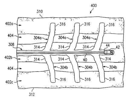
FIGURE ~ is a cross-sectional diagram illustrating an example multi-plane
drainage pattern 400 for accessing deposits in multiple layers 402 of
subterranean
deposits. Multi-plane drainage pattern 400 may provide access to multiple
layers 402
of subterranean deposits that may be separated by impermeable or substantially
impermeable material 404 such as sandstone, shale, or limestone. In this
embodiment, substantially horizontal portion 308, upwardly ramping well bore
304a,
and downwardly ramping well bore 304b may be formed as previously described in
connection with FIGURE 7.
Elongated portion 316 of upwardly ramping well bores 304a and downwardly
ramping well bores 304b may be of sufficient length to allow multi-plane
drainage
pattern 400 to intersect multiple coal seams or multiple layers 402 of any
other
subterranean zone. For example, ramping well bores 304 may extend in a
substantially vertical plane to provide access to an upper layer 402a and a
lower layer
402c. Although only three subterranean layers 402a-c are shown in FIGURE 7,
multi-plane drainage pattern 400 may intersect any appropriate number of
subterranean layers 402 to effectively drain the subterranean zone. For
example,
upwardly ramping well bores 304a and downwardly ramping well bores 304b may
travel through a number of subterranean layers 402 separated by multiple
layers of
impermeable or substantially impermeable material 404.
As was described with regard to FIGURE 7, mufti-plane drainage pattern 400
may also include ramping well bores 304 that extend from opposite portions of
elongated portion 116 of lateral well bores 110. Because ramping well bores
304 may
extend from lateral well bores 110 or main drainage well bore 104, mufti-plane
drainage pattern 400 may be modified as appropriate to adequately drain
multiple
layers 402 of subterranean deposits. Thus, mufti-plane well bore pattern 400
may
merely include a main drainage well bore 104 with ramping well bores 304. As
alternative embodiments, mufti-plane well bore pattern 400 may include a main
drainage well bore 104, lateral well bores 110, ramping well bores 304
extending
CA 02493380 2005-O1-11
WO 2004/007906 PCT/US2003/021626
1 ~7
A,
from the main drainage well bore 104 and/or the lateral well bores 110, or any
combination thereof. ~ther modifications and variations described with regard
to
FIGURE 7 may be made to mufti-plane drainage pattern 400 as appropriate.
FIGURE 9 is an isometric diagram illustrating an example mufti-plane
drainage pattern 500 for accessing deposits in a subterranean zone. In this
embodiment, the substantially horizontal portions of both the main drainage
well bore
104 and the elongated portions 116 of lateral well bores 110, which are
illustrated in
FIGURE 4, are replaced with the substantially horizontal well bore 308
described
with regard to FIGURES 8 and 9. Thus, as illustrated, drainage pattenl 500
includes
ramping well bores 504 extending from the main drainage well bore 508 and
extending from each lateral well bore 510. Alternatively, however, drainage
pattern
500 may include a main drainage well bore 508 with ramping well bores 504,
lateral
well bores 510 extending from a main drainage well bore 508 with ramping well
bores 504, or any combination thereof for producing entrained water,
hydrocarbons,
and other fluids from one or more layers. As was previously described, the
multi-
plane drainage pattern 500 may provide access to a single, thick layer 302 of
subterranean deposits as was described with regard to FIGURE 7. Alternatively,
mufti-plane drainage pattern 500 may provide access to multiple layers 402 of
subterranean deposits separated by impermeable or substantially impermeable
material such as sandstone, shale, or limestone, as was described with regard
to
FIGURE 8.
In particular embodiments of the present invention, lateral well bores 510 may
extend from opposite sides of main drainage well bore 508 to a periphery of
the area
being drained. Thus, a first set of lateral well bores S l0a may extend in
spaced apart
relation to each other from one side of main drainage well bore 508.
Similarly, a
second set of lateral well bores 510 may extend in spaced apart relation to
each other
from a second, opposite side of main drainage well bore 508. The first and
second
sets of lateral well bores 510 may mirror each other or may be offset from
each other
along the main drainage well bore 508. In particular embodiments, pairs of
lateral
well bores 510 may be substantially evenly spaced on each side of the main
drainage
CA 02493380 2005-O1-11
WO 2004/007906 PCT/US2003/021626
,~
z ~.~
well bore 508 and extend fiom the main drainage well bore 508 at an angle of
approximately 45 degrees.
The interval spacing between ramping well bores 504. may correspond to the
spacing interval between lateral well bores 510. If, for example, lateral well
bores
510 extend from the main drainage well bore 508 at three hundred foot
intervals,
ramping well bores 504 may also extend from the same point at three hundred
foot
intervals. In the illustrated embodiment of the present invention, a pair of
lateral well
bores 510 and at least one ramping well bore 504 intersect the main drainage
well
bore 508 at a single location. The at least one ramping well bore 304 may
comprise
an upwardly ramping well bore 504a, a downwardly ramping well bore 504b, or
both.
h1 an alternate embodiment, the at least one ramping well bore 504 and pair of
lateral
well bores 510 may not intersect the main drainage well bore 508 at a single
location.
Additionally, the spacing between ramping well bores 504 may not correspond to
the
spacing between lateral well bores 510. For example, the interval spacing
between
ramping well bores 504 may approximate three hundred feet, while the interval
spacing between lateral well bores 510 may approximate one hundred feet. One
skilled in the art may recognize that the spacings described are merely
exemplary.
Any appropriate interval spacing may be used to adequately cover the area to
be
drained.
Further, the interval spacing between ramping well bores 504 and/or lateral
well bores 510 may vary along main drainage well bore 508. For example, the
interval spacing between the first ramping well bore 504 and the second
ramping well
bore 504 may be approximately three hundred feet and the interval spacing
between
the second ramping well bore 504 and the third ramping well bore 504 may be
approximately two hundred feet. Similarly, the interval spacing between the
first
lateral 510 and the second lateral 510 may be approximately one hundred feet,
and the
interval spacing between the second lateral 510 and the third lateral 510 may
be
approximately fifty feet. The interval spacings given above are also only
exemplary.
One skilled in the art may recognize that the interval spacings separating
ramping
well bores 504 and/or lateral well bores 510 may be any appropriate interval
to
provide access to the one or more layers of subterranean deposits.
CA 02493380 2005-O1-11
WO 2004/007906 PCT/US2003/021626
1~
As gas described in greater detail with regard to FIGURE 4, each lateral well
bore 510 rnay also include a radiused portion S 14~ and an elongated portion
516. The
radiused portion 514 may connect the lateral well bore 510 to the main
drainage well
byre 508 at a predetermined radius of curvature. The appropriate radius of
curvature
may be dictated by drilling apparatus capabilities and/or by the dimensions of
the area
to be drained by the multi-plane well bore pattern 500. As previously
described, each
ramping well bore 504 may include a radiused portion 518 and an elongated
portion
520.
In particular embodiments, the radius of curvature of the radiused portion 518
of the ramping well bore 504 may be substantially equal to the radius of
curvature of
the radiused portion 514 of the lateral well bores 510. For example, if the
radius of
curvature for radiused portion 514 is three hundred feet, the radius of
curvature for
radiused portion 518 may also be three hundred feet. Alternatively, the radius
of
curvature of the radius portion 518 of the ramping well bore 504 may not
correspond
with the radius of curvature of the radiused portion 514 of the lateral well
bore 510.
Thus, while the radius of curvature for radiused portion 514 may be
approximately
three hundred feet, the radius of curvature of radiused portion 518 may be
approximately two hundred feet. Accordingly, the mufti-plane drainage pattern
500
may be customized as is necessary to optimize the draining of the one or more
layers
of subterranean deposits. The invention is not limited to the radius of
curvature
dimensions given above. Rather, the radius of curvature dimensions are merely
exemplary. It may be recognized by one spilled in the art that the radius of
curvature
of either radiused portion 514 or 518 may be any appropriate radius of
curvature to
provide access to the layer or layers of subterranean deposits.
A number of other variations and modifications may also be made to multi-
plane well bore pattern 500 as appropriate to allow for the rerrioval and
production of
hydrocarbons and other mineral deposits from one or more layers of
subterranean
deposits. For example, although FIGURE 9 depicts a plurality of upwardly
ramping
well bores 504a and downwardly ramping well bores 504b extending from opposite
sides of the main drainage well bore 508, mufti-plane well bore pattern 500
may
include only upwardly ramping well bores 504a or only one downwardly ramping
CA 02493380 2005-O1-11
WO 2004/007906 PCT/US2003/021626
well bores 504.b. ~ther suggested modifications were described with regards to
FICaIJRES 7 and 8 and may be appropriately applied to the embodiment of
FICIIJRE
9.
FICaURE 10 is a flow diagram illustrating an example method for producing
gas from a subterranean zone. In this embodiment, the method begins at step
600 in
which areas to be drained and drainage patterns to be used in the areas are
identified.
For example, drainage patterns 300, 400, or 500 may be used to provide
optimized
coverage for the region. It will be understood that any other suitable
patterns may
also or alternatively be used to degasify one or more layers of subterranean
deposits.
Proceeding to step 602, the substantially vertical well 12 is drilled from the
surface 14 through the subterranean zone. Next, at step 604, down hole logging
equipment is used to exactly identify the location of the target layer of
subterranean
deposits in the substantially vertical well bore 12. At step 606, the enlarged
diameter
cavity 20 may be formed in the substantially vertical well bore 12 at a
location within
the target layer of subterranean deposits. As previously discussed, the
enlarged
diameter cavity 20 may be formed by under reaming and other conventional
techniques. Next, at step 608, the articulated well bore 30 is drilled to
intersect the
enlarged diameter cavity 20. It should be understood that although the
drilling of a
dual well system is described in steps 602-608, any other appropriate
technique for
drilling into subterranean deposits may be used. After the subterranean
deposits are
reached, a drainage pattern may then be drilled in the deposits, as described
below.
At decisional step 610, it is determined whether ramping well bores 504
should be drilled. Ramping well bores 504 may extend upwardly or downwardly
from a main drainage well bore 508. In deciding whether to drill ramping well
bores
504, the size and accessibility of the layer or layers of subterranean
deposits may be
considered. In one embodiment of the present invention, it may be desirable to
drill
ramping well bores 504 to access minerals, gas, and water within a single,
thick layer
302 of subterranean deposits. Alternatively, ramping well bores 504 may
provide
access to multiple layers 402 of subterranean deposits that may be separated
by
impermeable or substantially impermeable material 404 such as shale,
limestone, or
sandstone. If at decisional step 610 it is determined that ramping well bores
504
CA 02493380 2005-O1-11
WO 2004/007906 PCT/US2003/021626
''~ i
.:. Z
should not be drilled, steps 612 through 614 are skipped and the method
proeeeds
directly to step 616. If instead, however, it is determined at decisional step
610 that
that ramping v~ell bores 504 should be chilled, any secondary subterranean
layers 402
of subterranean deposits, if any, may be identified at step 612. damping well
bores
504 are drilled at step 614.
At step 616, the articulated well bore 30 may be capped. Next, at step 61 ~,
the
enlarged cavity 20 is cleaned in preparation for installation of downhole
production
equipment. The enlarged diameter cavity 20 may be cleaned by pumping
compressed
air down the substantially vertical well bore 12 or by other suitable
techniques. At
step 620, production equipment is installed in the substantially vertical well
bore 12.
The production equipment may include a sucker rod pump extending down into the
cavity 20. The sucker rod pump may be used to remove water from the layer or
layers
of subterranean deposits. The removal of water will drop the pressure of the
subterranean layers and allow gas to diffuse and be produced up the annulus of
the
substantially vertical well bore 12.
Proceeding to step 622, water that drains from the drainage pattern into the
cavity 20 is pumped to the surface with the rod pumping unit. Water may be
continuously or intermittently pumped as needed to remove it from the cavity
20.
Additionally or alternatively, the drainage pattern may be used for
environmental
remediation purposes to treat or recover underground contaminants posing a
danger to
the environment. For example, the drainage pattern and cavity 20 may be used
to
inject a treatment solution into a contaminated coal seam or surrounding area,
recover
byproducts from the contaminated coal seam or surrounding area, or strip
recoverable
product from the coal seam. The drainage pattern may also be used for the
sequestration of gaseous emissions. For example, gaseous emissions such as
carbon
dioxide entrained in a Garner medium may be injected into the pattern with the
aid of
a surface pump. At step 624, gas diffused from the subterranean zone is
continuously
collected at the surface 14. Upon completion of production, the method is
completed.
Although the present invention has been described with several embodiments,
numerous changes, substitutions, variations, alterations, transformations, and
modifications may be suggested to one skilled in the art, and it is intended
that the
CA 02493380 2005-O1-11
WO 2004/007906 PCT/US2003/021626
~a
LL
present iri~enti~n enc~mpass all such ehanges, substitutions, ~raniatiens,
alterations,
transformations, and modifications as fall ~itlun the spirit and scope of the
appended
claims.