Note: Descriptions are shown in the official language in which they were submitted.
CA 02493481 2005-O1-21
TITLE: RECEPTACLE ASSEMBLY FOR A BOTTLED WATER DISPENSER
Field of the Invention
This invention relates to liquid dispensers, and in particular, to devices for
transferring water from a bottled water source to an internal reservoir in a
bottled
water dispenser.
Background of the Invention
For a number of reasons, it has become popular in offices and homes to have
bottled drinking or potable water. Dispensers are provided for the bottled
water.
The water normally comes in plastic bottles containing 5 US gallons or
approximately 19 litres of water. Early water dispensers had an internal
reservoir
and an open top, which allowed the water supply bottle to be mounted on top of
the dispenser in an inverted position with the neck of the water bottle
extending
into the reservoir. When the water level in the reservoir reaches the neck of
the
bottle, air can no longer enter the bottle, so water stops flowing from the
bottle.
When water is taken from the dispenser lowering the water level in the
reservoir,
the bottle neck is exposed allowing air again to enter the bottle. Water then
flows
again from the bottle to replenish the reservoir. A difficulty with these
early water
dispensers, however, is that water was often spilled while trying to invert
and
mount the somewhat heavy water supply bottle on the dispenser.
In order to try to overcome this spillage problem, attempts were made to put
closures or caps on the necks of the water supply bottles wherein these
closures
had spring-loaded plunger-type valves in them. When the water supply bottle
was
inverted and placed on top of the dispenser, the plunger would be depressed,
opening the valve allowing water to come out of the supply bottle. While this
reduced the spillage, the plunger-type valves were problematic and these types
of
caps were expensive.
1
CA 02493481 2005-O1-21
A similar approach, as shown in U.S. patent No. 4,699,188 issued to Henry
E. Baker et al, was to provide a water supply bottle with a plastic cap. The
cap had
a central, axial recess, and the dispenser was provided with an inlet tube
with a
sharpened upper end, so that when the water supply bottle was inverted and
mounted on the dispenser, the sharpened tube would enter the cap recess and
pierce the cap at the inner end of the recess allowing water to flow through
the
inlet tube into the dispenser reservoir. If there is a good seal between the
water
supply bottle cap and the piercing inlet tube of the dispenser, this Baker
system
works fine. However, this is usually not the case, so some water leaks out
around
the inlet tube and surrounds the supply bottle cap. This leaked water
accumulates
and stagnates and can be a source of bacteria that gets into the water supply.
Summaryr of the Invention
In the present invention, a receptacle is provided that has a funnel portion
that accepts the neck of a water supply bottle. The funnel portion has a
bottom
wall portion with an opening therethrough, so that any water that surrounds
the
supply bottle cap can drain out of the funnel portion and not stagnate
therein.
According to the invention, there is provided a receptacle for delivering
liquid
from an inverted supply bottle to a reservoir in a dispenser. The receptacle
is used
with water supply bottles having a narrow neck closed by a cap having a
central,
axial recess with a frangible bottom. The receptacle comprises a bottle
support
member having an annular rim for supporting a supply bottle in an inverted
mounted position. The support member also has a downwardly depending funnel
portion extending below the rim which is adapted to receive the bottle neck.
The
funnel portion has a bottom wall portion defining at least one opening for the
passage of liquid from the funnel portion to the dispenser reservoir. The
bottle wall
portion is spaced below the neck of a mounted supply water bottle. An elongate
piercing probe extends upwardly from the bottom wall portion a sufficient
distance
to break the cap frangible bottom of a mounted supply bottle. Also, the
piercing
2
CA 02493481 2005-O1-21
probe has at least one longitudinal exterior groove adapted to extend through
a
broken cap frangible bottom of a mounted supply bottle for the passage of
liquid
from inside the supply bottle into the funnel portion.
Brief Description of the Drawings
Preferred embodiments of the invention will now be described, by way of
example, with reference to the accompanying drawings, in which:
Figure 1 is a diagrammatic partial elevational view, partly in section,
showing
a prior art receptacle assembly;
Figure 2 is a diagrammatic elevational view similar to Figure 1, but showing a
preferred embodiment of a receptacle assembly according to the present
invention;
Figure 3 is a exploded view of the embodiment of Figure 1 showing a water
supply bottle about to be mounted on a receptacle assembly;
Figure 4 is a cross-sectional view taken along lines 4-4 of Figure 3;
Figure 5 is a cross-sectional view of the piercing probe and probe support
used in the embodiment of Figures 2 to 4, as viewed in the direction of arrows
5-5
of Figure 4;
Figure 6 is a diagrammatic cross-sectional view of another preferred
embodiment of a receptacle assembly according to the present invention;
Figure 7 is a plan view of the embodiment shown in Figure 6;
3
CA 02493481 2005-O1-21
Figure 8 is a cross-sectional view of the probe and probe support of the
embodiment shown in Figures 6 and 7 as viewed in the direction of arrows 8-8
of
Figure 7;
Figure 9 is a bottom view of the filter canister used in some of the preferred
embodiments of the invention;
Figure 10 is a cross-sectional view, partly broken away, showing some
possible modifications to the preferred embodiments of the present invention;
Figure 11 is an enlarged elevational view of the upper end of another
preferred embodiment of the piercing probe according to the present invention;
Figure 12 is another preferred embodiment of a receptacle assembly
according to the present invention;
Figure 13 is a cross-sectional view taken along lines 13-13 of Figure 12;
Figure 14 is an elevational view of another preferred embodiment of a probe
and probe support according to the present invention;
Figure 15 is a top plan view of the embodiment shown in Figure 14;
Figures 16 to 19 are cross-sectional views of yet further preferred
embodiments of the piercing probes according to the present invention;
Figure 20 is an elevational view of yet another preferred embodiment of a
piercing probe and probe support according to the present invention;
4
CA 02493481 2005-O1-21
Figure 21 is a vertical cross-sectional view of the embodiment shown in
Figure 20;
Figure 22 is an elevational view of yet a further preferred embodiment of a
probe and probe support according to the present invention; and
Figure 23 is a vertical cross-sectional view of the embodiment shown in
Figure 22.
Detailed Descria~tion of the Preferred Embodiments
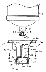
Referring firstly to Figure 1, a prior art receptacle 10 for a bottled water
dispenser is shown with a water bottle 12 mounted thereon. Water bottle 12 has
a
narrow neck 14 that extends downwardly into a cup-like member 16. Bottle 12
comes with a plastic cap 18 that has a central axial recess 20. The receptacle
10
includes a tubular probe 22 having an upper inlet hole 24, so that when the
bottle
12 is mounted on receptacle 10, probe 22 enters the axial recess 20 in cap 18,
pierces the cap, and allows inlet opening 24 to receive the water inside
bottle 12
and deliver it downwardly into a reservoir (not shown) of the bottled water
dispenser.
Ideally, the probe 22 in axial recess 20 is dimensioned to provide a seal
therebetween, so that all of the water inside the bottle is eventually
delivered to the
dispenser reservoir. However, the seal often leaks, or sometimes the bottle 12
is
removed from receptacle 10 before all of the water is emptied from it, in
which case
some residual water 26 collects in the bottom of the cup-like member 16. There
is
no way for this residual water to escape, so it stagnates and offers a
breeding
ground for bacteria which can eventually migrate to the water inside bottle
12.
Turning now to the present invention, a preferred embodiment of a
receptacle assembly for a bottled water dispenser is generally indicated in
Figures 2
5
CA 02493481 2005-O1-21
and 3 by reference numeral 30. Receptacle assembly 30 includes a bottle
support
member 32 having an annular rim for supporting a water supply bottle 12
thereon
in an inverted mounted position, as indicated in Figure 2. Support member 32
has
a downwardly depending funnel portion 36 extending below rim 34. The funnel
portion has an upright sidewall 38 including a curved upper portion 40
extending
downwardly and inwardly from annular rim 34. Sidewall 38 is adapted to receive
the bottle neck 14. Funnel portion 36 has a bottom wall portion 42 which
defines at
least one opening 44 for the passage of liquid, such as water, from the funnel
portion 36 downwardly to a reservoir (not shown) in the dispenser located
below
receptacle assembly 30.
It will be noted that bottom wall portion 44 is spaced below the bottle neck
14, so that any water in funnel portion 36 can drain out through openings 44.
Actually, in use, the water rises to the bottom edge of cap 18 and cannot rise
any
higher, because air cannot then enter bottle 12 allowing more water to come
out of
the bottle. The water in funnel portion 36 may completely drain out of
openings 44
when an empty bottle 12 is removed, but at least the water in funnel portion
36 is
constantly being removed and replenished, so that it cannot stagnate and
become a
breeding ground for bacteria.
Referring next to Figures 4 and 5, a probe assembly 46 is shown, which
includes an elongate piercing probe 48 and a probe support portion 50. In the
receptacle assembly 30 shown in Figures 2 to 6, the probe support portion 50
actually forms part of bottom wall portion 42, and the outlet or drain
openings 44
are actually located in probe support 50.
As seen best in Figures 2 and 3, piercing probe 48 extends upwardly from
bottom wall portion 42 a sufficient distance to enter cap recess 20 and pierce
or
spread open the inner end or frangible bottom 52 (see Figure 3) of the portion
of
cap 18 that forms recess 20.
6
CA 02493481 2005-O1-21
Piercing probe 48 has at least one longitudinal exterior groove 54 which
extends through or passes the broken bottle cap frangible bottom 52 when
bottle
12 is mounted on receptacle assembly 30, as indicated in Figure 2. This allows
water to flow from inside bottle 12 along the probe and into the funnel
portion 36.
As.best seen in Figures 4 and 5, the longitudinal grooves 54 in probe 48 are
defined by longitudinal flanges or ribs 56. Radially disposed support gussets
51 are
provided to strengthen the base of probe 48.
Probe 48 has a non-tubular, solid cross-section. Probe 48 has a rounded
upper or distal end portion 58 that actually does the piercing or splitting or
breaking
of the supply bottle cap frangible bottom 52. Some water supply bottles have
caps
18 that are provided with cup-like members or plugs (not shown) that form the
frangible bottom 52 of recess 20. These cup-like members are made so that they
can break off when the piercing probe enters recess 20, and there are
interlocking
annular flanges that allow these cup-like members to be reattached as the
piercing
probe is withdrawn from the water bottle or the water bottle is lifted off the
probe.
This type of water bottle is referred to as a resealable water bottle, so that
it can be
removed from the water dispenser before it is empty. In order to reseal the
cup-
like members, the piercing probe usually has a transverse groove or notches 60
in
the distal end portion 58, which grabs and retains an annular flange on the
cup-like
members and pulls the cup-like member back into position to re-seal the cap
when
the water bottle is lifted off the dispenser.
As seen best in Figures 3 to 5, the probe support 50 is releasably mounted
in the bottom wall portion 42. One way that this is done, as seen best in
Figure 4,
is to provide a probe support 50 with radially outwardly disposed tabs 62, and
the
bottom edge of sidewall 38 with circumferential recesses 64. Probe support 50
can
then be rotated until tabs 62 line up with recesses 64 to allow the probe
support 50
7
CA 02493481 2005-O1-21
and funnel portion 36 to be axially separated. The reverse procedure is used
to
attach probe support 50 to funnel portion 36, and this releasable mount or
connection is referred to herein as a twist lock. Another way to provide this
releasable mounting is to threadably attach probe support 50 to the sidewall
38, as
seen best in Figure 6. The probe support 50 has male threads 66 (see Figure 8)
and the lower end of sidewall 38 as mating female threads 68.
Referring again to Figures 2, 3 and 6, probe support 50 has an optional
demountable canister 70 threadably mounted thereon. Canister 70 has a
foraminous lower wall as seen best in Figure 9 where the bottom wall 72 has a
plurality of holes 74 formed therein. Canister 70 may be filled with a filter
medium
76, such as a suitable foam impregnated with activated charcoal.
Alternatively,
canister 70 could simply be filled with activated charcoal if holes 74 are
made small
enough to prevent the charcoal from escaping or a suitable filter medium is
placed
between the activated charcoal and bottom wall 72. Either way, canister 70 is
in
communication with bottom wall portion openings 44 and openings 74 to allow
water to pass from funnel portion 36 through canister 70 to the reservoir in
the
bottled water dispenser.
Figures 6 and 7 illustrate that probe 48 could have a truncated conical upper
or distal end portion 78. The probe distal end portion could also be
hemispherical
or it could have other configurations as well, as discussed further below, as
long as
it has a transverse width sufficient to split open the frangible bottom 52 of
the
supply bottle cap central axial recess 20 where this frangible bottom is of
the
simple non-reseaiable type mentioned above.
Figure 10 shows a modification where the funnel wall bottom portion 42 has
side openings 80 as well as or instead of the bottom openings 44 in probe
support
50. In this embodiment, the canister 70 would not be used, although the lower
portion 82 of probe support 50 could still be provided with threads 84 to
permit the
8
CA 02493481 2005-O1-21
addition of a filtering canister at a later date, if desired. In this latter
event, a
funnel portion 36 not having openings 80 would be used.
Figure 11 shows an alternate embodiment for piercing probe 48 where the
upper or distal end portion 86 has a plurality of transverse projections 88
arranged
in a horizontal ring. These projections 88 would be used with releasable type
supply water bottle caps where cup-like members or detachable plugs are formed
on the inner end of the axial recess 20 in the bottle caps 18. These
projections 88
would releasably engage the releasable cap plugs to allow the plugs to be
reattached as the water bottle is pulled off probe 48.
Figures 12 and 13 show another preferred embodiment of a receptacle
assembly 90 where the bottle support member 92 and the piercing probe 94 are
formed as one integral unit. As seen best in Figure 13, four sector-like
openings
are provided in the bottom wall portion 98 to allow the water to pass
downwardly
out of funnel portion 100. Receptacle assembly 90 also has a downwardly
disposed
lower tubular portion 102. This allows for a lower water level in the
reservoir of a
water bottle dispenser, because lower opening 104 now provides the gateway for
air passing upwardly into a supply water bottle.
Figures 14 and 15 show a modified probe assembly 104 which is similar to
the probe assembly shown in Figure 8, but where the probe ribs 106 extend all
the
way to the top of the probe. Upper or distal end portion 108 also has a ring
of
radial projections 110 that perform the same function as the projections 88 in
the
embodiment of Figure 11 in connection with the resealable-type of supply water
bottle caps.
Figure 16 to 19 show various other possible preferred configurations for the
piercing probe of the present invention. In Figure 16, there are three
transversely
9
CA 02493481 2005-O1-21
disposed longitudinal ribs 112. The longitudinal grooves 114 for the flow of
water
along the probe are provided between adjacent ones of the ribs 112.
Figure 17 illustrate that the probe longitudinal ribs 116 can have laterally
disposed, outer, longitudinal flanges 118. Again, the longitudinal grooves 120
are
defined between adjacent ones of the ribs and flanges 116, 118.
Figures 18 and 19 show probes having arcuate elongate wall portions. In
Figure 18, a single arcuate elongate wall portion 120 defines a single
longitudinal
groove 122. Longitudinal groove 122 appears to be in the inside of arcuate
wall
portion 120 but for the purposes of the present invention it is considered to
be a
longitudinal exterior groove, because it is open to the exterior of the probe,
as
opposed to being of the enclosed tubular-type of probe found in the prior art.
Figure 19 has a pair of opposed arcuate elongate wall portions 124 joined by
a central flange 126, again to provide two longitudinal outwardly exposed
exterior
grooves 128 for the flow of water along the probe.
Figures 20 and 21 show a probe assembly 130 having a helical or spiral rib
132 defining the longitudinal exterior groove 134 between adjacent revolutions
of
the helical ribs.
Figures 22 and 23 show a probe assembly 136 in the form of a helical coil
138. The longitudinal exterior groove 140 is formed between adjacent turns of
helical coil 138.
It will be appreciated that the features described in the various embodiments
discussed could be mixed and matched as desired.
CA 02493481 2005-O1-21
As will be apparent to those skilled in the art in light of the foregoing
disclosure, many alterations and modifications are possible in the practice of
this
invention without departing from the spirit or scope thereof. Accordingly, the
scope
of the invention is to be construed in accordance with the substance defined
by the
following claims.
11