Note: Descriptions are shown in the official language in which they were submitted.
CA 02493552 2009-07-22
TITLE OF THE INVENTION
DEVICE FOR SIMULTANEOUSLY CASING A HOLE WHILE DRILLING
TECHNICAL FIELD OF THE INVENTION
This invention relates generally to installation of pipes into a formation, or
crust of the earth, while constructing a borehole. More particularly, the
invention may
be used with different types of rotary drill rigs and rotary devices to
install a casing in
a hole while the hole is being drilled.
BACKGROUND OF THE INVENTION
Drilling a well hole typically involves drilling to a certain depth with a
drill bit
mounted on a drill string, then removing the drill string from the hole in
order to case
the hole. The pipe or casing is driven into the hole by repeated impact.
Generally it is
not desirable to drill too far down before casing the hole, as the sides of an
uncased
hole may be susceptible to collapse and to leaks from the surrounding
formation. The
drill-then-case process has to be repeated several times to produce a deep
hole.
Drilling a hole can therefore be a time-consuming process. To maximize
production
and profits, it is necessary to minimize the time spent completing a hole.
Advancing a pipe into the earth usually requires costly, heavy and cumbersome
equipment, including a massive driving device to either develop the impact
energy or
to transmit impact energy to the pipe or casing. The device must be securely
mounted
on a drill rig, necessitating modifications to the drill rig to be able to
handle the
driving device. Existing driving devices are generally large and require
additional
1
CA 02493552 2009-07-22
equipment for their operation, such as hydraulic pumps or air compressors.
Once
installed on a rig, a driving device is usually difficult to remove.
U.S. Patent No. 3,895,680 to Cook discloses a hammer by which a pipe may be
driven into the ground, without any type of drilling mechanism. A heavy,
hollow ram
is raised by a pair of air cylinders mounted on the outside of the ram. The
ram travels
downward transmitting a blow to the pipe being installed. The force of the
blow is
determined by the weight of the ram. The system requires an external source of
compressed air and a complex control system. The force of the impact is not
adjustable, as might be desired when casing in softer or less dense strata.
Drilling equipment or drilling rigs come in various sizes, with different
hoisting systems and various tower configurations. A common approach is to
modify
the tower and equipment to adapt to the driving device. Due to the size and
operational methods, several drilling rigs have towers and hoisting
capabilities, which
are too small to adapt to the installation of conventional casing driving
equipment.
It is known in the art to case the hole while drilling as a means of improving
the speed and efficiency of the drilling process. The present invention relies
on a
simple casing driver which is small, easy to handle and adaptable for various
drilling
rigs, in contrast to many of the other prior art devices, which rely on heavy,
cumbersome machinery and require special handling procedures. Further, the
prior
art devices, generally being controlled by hydraulic or pneumatic means,
require an
independent source of power, and controls for that power.
U.S. Patent No. 3,833,072 to Back illustrates a drilling machine including a
casing-driving element. While the device is intended to be relatively low
weight and
portable, it still requires an external source of hydraulic pressure, and a
complex
intermittent pressure regulation system to operate the driver.
2
CA 02493552 2009-07-22
U.S. Patent No. 4,232,752 to Hauk et al. employs a lightweight, short stroke
annular piston, while increasing the rate of impact on the casing. Each
individual
impact is low energy, which is compensated by the increased frequency of the
impacts. As in Cook, the piston is pneumatically driven. The driver further
includes
a complex set of valve chambers and passages to maximize the efficiency of
pneumatic system.
In U.S. Patent No. 6,029,757, Anderson et al. disclose a casing hammer
assembly containing a central aperture surrounding a drill string. To drive
the casing,
a reciprocating hammer strikes an impact anvil surrounding the central
aperture.
Anderson et al. manage to avoid the use of pneumatic or hydraulic means to
operate
the hammer, instead reciprocating the hammer by use of an eccentric
arrangement.
This arrangement involves sprockets and chains driven by a rotating shaft and
sleeve.
The shaft itself is driven by a motor, which requires its own power source.
However,
the relatively complex arrangement of chains and sprockets between the shaft
and the
hammer leaves the entire assembly more vulnerable to failure. The use of a
separate
motor results in an additional part that could fail or need maintenance.
Further, the
entire assembly is suspended from the drilling rig above the casing pipe by a
set of
cable pulleys and cables, which could cause problems with the storage of the
driver
when not in use.
U.S. Patent No. 6,371,209 to Allyn et al. discloses a device for the removal
of
casing. The device disclosed by Allyn et al. relies upon an existing pneumatic
hammer drill for it to operate, and a source of power. Allyn et al. rotates
the pipe or
casing to install it, which requires that the ends of the each pipe be
threaded.
It is one object of the invention to provide a new method of advancing pipe
into the earth.
3
CA 02493552 2009-07-22
It is a further object of the invention to provide a method of advancing pipe
without the need for air or hydraulics to operate the device.
It is an object of the invention to provide a driving device which is
versatile, in
that it may be used on virtually any existing drill rigs without modification
to the drill
rigs in order to use the driver.
It is a further object of the invention to provide a driving device which is
easily
attached to a string of drilling tools being rotated by a drilling rig or
rotating device.
It is a further object of the invention to provide a driving device which,
once
attached to the drill string, can be selectively operated, allowing the drill
crew to drill
without hammering, yet without physically removing the driver from the drill
string.
These and other objects of the invention will be appreciated by reference to
the
summary of the invention and to the detailed description of the preferred
embodiment
that follow. It will be appreciated that all of the foregoing objectives may
not be
satisfied simultaneously by the preferred embodiment or by each of the claims.
SUMMARY OF THE INVENTION
The invention is a driving device for driving pipes or casing into the ground
while a hole is being drilled. The driving device is placed on a rotary drill
stem,
above the casing. If the driving device is not attached directly to the drill
stem, the
stem may be rotated, advanced or retracted freely. However, once the driver is
clamped to the drill stem, it harnesses the rotational force of the drill stem
to provide a
vertical impact force to the pipe or casing. Because the driver impacts the
casing
4
CA 02493552 2009-07-22
twice for every rotation of the drill stem, the frequency of the impacts
varies with the
speed of the drill stem.
The driving device uses the existing rotary drill string and its controls to
enable
handling and operation functions and to simultaneously install a casing as the
hole is
drilled. Because the driving device makes contact with the drill string, and
uses the
downward pressure and rotation of the string to install a casing, there is no
need for
external hydraulic or pneumatic equipment to operate the driving device.
Because of its simplicity, the driving device is relatively small, and can be
transported in a light service truck. The driving device can be used with many
types
of rotary drilling equipment, or rotating devices, without modifying them.
The device is easily operated by a technician versed in installation of casing
while drilling a hole. A machinist, qualified in the operation of milling and
lathe
equipment, can manufacture the device in a machine shop from available metals.
In one aspect the invention comprises a method of installing a pipe or casing,
comprising the steps of capturing rotational force supplied by an external
driver,
storing energy derived from the rotational force, converting the energy to an
impact
force, and transmitting the impact force to the pipe or casing. The invention
may
further comprise capturing a downward force applied to the external driver and
transmitting the downward force to the pipe or casing.
In one embodiment, the invention relates to a device, using an external
driver,
to install a pipe or casing, comprising a first portion adapted to capture an
axial
rotational force supplied by the external driver along a central axis, a
second portion
adapted to store energy derived from the external driver's rotational force
and to
convert the stored energy to an impact force, and a third portion adapted to
transmit
5
CA 02493552 2009-07-22
the impact force to the pipe or casing. The invention may further comprise a
fourth
portion, namely a shaft shaped to encircle the external driver while fitting
within the
first, second and third portions along the central axis.
In one aspect of the first embodiment of the invention, the first portion of
the
invention may comprise a carrier device surrounding a section of the external
driver,
and means, such as slips or clamps, to connect the carrier device to the
external driver.
The carrier device may comprise a generally hollow cylinder, adapted to
accommodate a section of the external driver through an axially central
aperture and
to accommodate part of the second portion of the device.
In a further aspect, the second portion may comprise an upper portion, which
rotates about a central axis under the rotational force of the driver, and a
lower
portion. The upper and lower portions may further comprise facing inclined
surfaces
which cooperate to move the upper portion away from the lower portion along
the
central axis upon partial rotation of the upper and lower portions, and
further
cooperate to allow the upper portion to move back towards the lower portion
along
the central axis upon further relative rotation of the upper and lower
portions. The
further cooperation may comprise a sudden cessation of direct contact between
the
inclined surfaces.
In another aspect, the invention may include at least one spring, which
compresses and expands as the upper portion and lower portion move away from
and
toward each other.
In a further aspect, the third portion may comprise an upper surface, adapted
to
receive an impact force from the second portion, and a lower surface in direct
contact
with an uppermost part of the pipe or casing. The third portion may further
comprise
an outlet to allow air to escape from the third portion.
6
CA 02493552 2009-07-22
In another embodiment, the invention comprises a device for installing a pipe
or casing using an external rotary driver which produces a rotational force,
comprising means to directly connect the device to the external rotary driver,
a central
shaft encircling a portion of the external rotary driver, a hammer, an anvil,
one or
more springs and a generally cylindrical carrier device. The carrier device
and
hammer may be operatively connected to rotate in concert under the rotational
force,
such that the rotational force causes the hammer to provide a first impact
force to the
anvil, and the first impact force causes the anvil to provide a second impact
force to
the pipe or casing.
In another embodiment, the invention comprises a device for installing a pipe
or casing, using an external driver, comprising a first portion adapted to
capture an
axial rotational force supplied by the external driver along a central axis,
and a second
portion adapted to store energy derived from the rotational force, to convert
the
energy to an impact force and to transmit the impact force to the pipe or
casing.
In one aspect, the first portion of this embodiment of the invention may
comprise a carrier device surrounding a section of the external driver and
means, such
as slips or clamps, to connect the carrier device to the external driver. In
another
aspect, the carrier device may be a generally hollow cylinder, with an axially
central
aperture to accommodate a section of the external driver and adapted to
accommodate
part of the second portion of the device.
In a further aspect, the second portion may comprise an upper portion, which
rotates about a central axis under the rotational force of the driver, and a
lower
portion. The upper and lower portions may further comprise facing inclined
surfaces
which cooperate to move the upper portion away from the lower portion along
the
central axis upon partial rotation of the upper and lower portions, and
further
7
CA 02493552 2009-07-22
cooperate to allow the upper portion to move back towards the lower portion
along
the central axis upon further relative rotation of the upper and lower
portions. The
further cooperation may comprise a sudden cessation of direct contact between
the
inclined surfaces. The second portion may further comprise an outlet to allow
air to
escape from the second portion.
In another aspect, the invention may include at least one spring, which
compresses and expands as the upper portion and lower portion move away from
and
toward each other.
In another aspect, this embodiment of the invention may further comprise a
third portion, namely a shaft shaped to encircle the external driver while
fitting within
the first and second portions along the central axis.
In another aspect, each embodiment may further comprise means to capture a
downward force applied to the external driver, to store the captured downward
force,
and to transmit the stored downward force to the pipe or casing. One or more
springs
may be used to capture, store and transmit the downward force, and the
transmittal
may be essentially constant through the installation procedure.
The foregoing was intended as a broad summary only and of only some of the
aspects of the invention. It was not intended to define the limits or
requirements of
the invention. Other aspects of the invention will be appreciated by reference
to the
detailed description of the preferred embodiment and to the claims.
S
CA 02493552 2009-07-22
BRIEF DESCRIPTION OF THE DRAWINGS
The preferred embodiment of the invention will be described by reference to
the drawings in which:
Fig. 1 is a sectional view of the driver, clamped into place on a drill stem
above
a pipe or casing.
Fig. 2 is an exploded view of the driver.
Fig. 3 is a partial sectional view of the driver of Fig. 1, in an extended, or
loaded, position.
Fig. 3A is a perspective cutaway view of the carrier component of the driver.
Fig. 3B is a perspective view of the driver of Fig. 1, in an extended, or
loaded,
position.
Fig. 4 is a partial sectional view of the driver of Fig. 1, in an impact
position.
Fig. 4A is a perspective cutaway view of the hammer component of the driver.
Fig. 4B is a perspective view of the driver of Fig. 1, in an impact position.
Fig. 5 is a partial sectional view of the driver of Fig.. 1, in a partially
loaded
position.
Fig. 5A is a perspective cutaway view of the sub anvil component of the
driver.
9
CA 02493552 2009-07-22
Fig. 5B is a perspective view of the driver of Fig. 1, in a partially loaded
position.
DETAILED DESCRIPTION OF THE PREFERRED EMBODIMENT
OF THE INVENTION
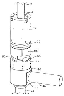
Referring to Fig. 1, the invention relates to a driving device which may be
installed directly on a drill stem 2 to assist in driving a pipe or casing 42
into the
ground. In operation, the driver is attached directly to drill stem 2 via any
suitable
mechanism, such as clamps or slips 4. Anvil 40, at the lowermost end of the
driving
device, rests on the top edge of pipe or casing 42. When the drill stem 2 is
to be
operated without hammering a pipe or casing 42, clamps or slips 4 may be
released,
allowing free rotation, advancement or retraction of the drill stem 2 without
affecting
the driving device.
The individual components of the preferred embodiment of the invention are
best shown in Figs. 1 and 2. Clamps or slips 4 rest on top of carrier 6.
Carrier 6 (best
illustrated in Fig. 3A) is a generally cylindrical piece with a central
aperture 46
through which the drill stem 2 (shown in Fig. 1 only) extends. In the
preferred
embodiment of the invention, the topside of carrier 6 is formed to securely
hold
clamps or slips 4, though it will be understood that clamps or slips 4 may be
attached
to carrier 6 in any appropriately secure manner. The underside 48 of carrier 6
is
hollow, the purpose of which is explained below.
Typically, a downward force is applied to drill stem 2, via pull down chains
or
like equipment. Inner advance spring 12 captures the downward force applied to
drill
stem 2, as explained below. Inner advance spring 12 may be encased, for
example, in
a spring carrier, which may comprise a top section 10 and bottom section 14.
The
CA 02493552 2009-07-22
spring carrier is intended to hold inner advance spring 12 in an optimum
vertical
position, allowing for the most efficient energy transfer during operation of
the
driving device.
Dust seals, such as those illustrated at 8 and 34, may be employed to seal the
assembly and prevent damage that may be caused by flying debris during
drilling and
driving operations.
Thrust bearing 16 and sub anvil receiver plate 18 between inner advance spring
12 and outer hammer spring 22 distribute all vertical forces evenly around the
circumference of the driving device, ensuring all forces are properly
vertically
directed. This ensures that pipe or casing 42 is being driven or pulled
exactly in the
desired direction, without wasting energy by dissipating it laterally from the
driving
device.
Hammer 26 comprises a generally cylindrical piece, with a central aperture.
The diameter of the upper portion of hammer 26, which shall be referred to as
the
upper cam surface, is such that it fits inside the hollow underside 48 of
carrier 6, with
the central aperture 46 of carrier 6 and the central aperture of hammer 26
being
generally aligned. A partial view of hammer 26 is shown in Fig. 4A.
Outer hammer spring 22 is sized to fit around the outside of the upper cam
surface of hammer 26. A diametrically larger portion of the hammer 26 creates
a
shoulder 50 around the circumference of hammer 26. The shoulder 50 prevents
outer
hammer spring 22 from completely sliding down around hammer 26. Outer hammer
spring 22 is thereby kept in place between the shoulder 50 and the lowermost
edge of
carrier 6.
11
CA 02493552 2009-07-22
Figure 1 best illustrates the interconnection of carrier 6 and hammer 26 to
contain the upper dust seal 8, inner advance spring 12, inner spring carrier
10, 14,
thrust bearing 16 and sub anvil receiver plate 18 in the hollow underside 48
of carrier
6, as well as the placement of outer hammer spring 22.
When assembling the driving device, sub anvil 24 is threaded through the
central aperture of hammer 26, such that hammer 26 rests on a lower impact
plate 28
at the bottom of the sub anvil. The lower impact plate 28 may be used to hold
the
hammer 26 in the proper position relative to sub anvil 24, as well as to
evenly
distribute any downward impact of the hammer 26. Sub anvil receiver plate 18,
thrust
bearing 16, inner spring carrier 10, 14, inner advance spring 12 and upper
dust seal 8
are likewise threaded onto sub anvil 24. The assembly is topped with carrier
6, with
sub anvil 24 partially extending through the central aperture 46 of carrier 6.
Sub anvil 24 provides a stable central shaft for the driving device, which
allows the driving device to surround drill stem 2 without interference unless
slips or
clamps 4 are engaged to fasten the driving device to the drill stem 2. While
Fig. 1
shows sub anvil 24 with an inner diameter just larger than the outer diameter
of drill
stem 2, sub anvil 24 also allows the use of the driving device on a drill stem
2 with a
narrower diameter. The inner diameter of sub anvil 24 is preferably
sufficiently large
that drill stem 2 does not interfere with sub anvil 24, or cause it to rotate.
Means such as splines 20 (best shown in Figs. 1 and 2) may be used to
interlock the upper cam surface of hammer 26 with grooves 44 in the underside
48 of
carrier 6 (as shown in Fig. 3A), thereby ensuring that rotation of drill stem
2 is
properly transmitted to hammer 26. Hammer 26 and carrier 6 therefore move in
concert.
12
CA 02493552 2009-07-22
The lower edge of the diametrically enlarged portion of hammer 26 comprises
an inclined surface 52. The inclined surface 52 interacts with the upper
surface 54 of
cam 30, which is likewise inclined. Inclined surfaces 52254 culminate in one
or more
points or tips. Wheel or roller devices may be placed at the points or tips,
to ensure
smooth interaction of inclined surfaces 52, 54. The interaction of the
inclined
surfaces 52, 54 is explained in more detail below.
The bottom surface of lower impact plate 28 rests on the anvil face 32. Cam
30 encircles the joint between lower impact plate 28 and anvil 40 and may be
bolted
in place to ensure close contact between anvil face 32 and lower impact plate
28.
The lower end of anvil 40 is designed to accommodate the end of pipe or
casing 42. As shown in Fig. 1, pipe or casing 42 may fit inside the lower end
of anvil
40, where pipe or casing 42 abuts a shoulder. The lower end of anvil 40 may
also fit
inside pipe or casing 42, such that the driving device is capable of driving
pipes or
casing 42 of varying diameters. Impact forces from the hammer 26 are
transmitted
through the anvil 40 to the uppermost edge of pipe or casing 42, thereby
driving pipe
or casing 42 into the ground.
For clarity, all parts of the driving device from the lower impact plate 28
and
below will be referred to as the lower portion of the driving device. The
lower
portion of the driving device does not rotate. Friction between the lower
surface of
the anvil 40 and the pipe or casing 42 prevents anvil. 40 from moving with the
rotation
of drill stem 2.
The driving device further comprises anvil outlet 36, which may be connected
to anvil 40 via any suitable means, such as anvil outlet retainer 38. Anvil
outlet 36
prevents air inside the pipe or casing 42 from absorbing the impact energy of
hammer
26 striking anvil 40. Anvil outlet 36 may also be oriented such that it abuts
a portion
13
CA 02493552 2009-07-22
of the supporting drilling rig, further preventing rotation of the lower
portion of the
driving device.
The operation of the dristing device to install a pipe or casing 42 may be
described by reference to Figs. 3, 3B, 4, 4B, 5 and 5B. In operation, a
constant
downward force is applied to drill stem 2, in addition to any rotational
force. Such
downward force is applied through use of pull down chains or like equipment.
For
example, a weight, which may be on the order of 50,000 pounds, may be attached
to
drill stem 2. The downward force compresses inner advance spring 12, as shown
in
Figs. 3 and 3B, and pre-loads outer hammer spring 22.
Drill stem 2 rotates and advances, causing a similar rotation in carrier 6.
Because splines 20 (shown only in Figs. 3, 4 and 5) connect hammer 26 to
carrier 6,
carrier 6 rotation causes hammer 26 to rotate in concert. As cam 30 is bolted
to the
immovable lower portion of the driving device, the inclined upper surface 54
of cam
30 does not rotate. The inclined lower surface 52 at the lower edge of the
diametrically enlarged portion of hammer 26 therefore interacts with the
inclined
upper edge 54 of cam 30 as hammer 26 rotates. The interaction of the two
inclined
surfaces 52, 54 forces hammer 26 up towards its extended or loaded position
and
further compresses spring 22, storing energy. The rotation of hammer 26
continues,
until eventually the interacting inclined surfaces 52, 54 reach the point
illustrated in
Figs. 3 and 3B, where only small points on the inclined surfaces 52, 54 are in
contact
with one another. At this point, the driving device is in its fully extended
or loaded
position.
Further rotation of the drill stem 2 and the hammer 26 causes the points that
were in contact in Figs. 3 and 3B to slip past each other, as shown in Figs. 4
and 4B.
Upon the sudden release of upward pressure, the lower portion of hammer 26
moves
downward rapidly, impacting anvil 40 (through lower impact plate 28, if
present) and
14
CA 02493552 2009-07-22
driving pipe or casing 42 down. Springs 12, 22 are released from compression,
adding stored energy to the downward force exerted on pipe or casing 42. The
driving device is thus in an impact position.
Continued rotation of the drill stem 2 and hammer 26 resets the driving device
for another blow. The inclined surface 52 of the hammer 26 slides over the
inclined
surface 54 of cam 30, again compressing the spring 22 and storing energy for
the next
driving impact. The interaction of the inclined surfaces 52, 54 between blows
of the
hammer 26, when the device is in a partially loaded position, is best shown in
Figs. 5
and 5B. Because the inclined surface 54 of cam 30 contains two points, the
hammer
26 strikes two blows for each rotation of drill stem 2.
During rotation of drill stem 2 between blows, inner advance spring 12
provides a constant downward force on pipe or casing 42, arising from the
downward
force applied to the drill stem 2. The constant downward force keeps the
driving
device in constant contact with pipe or casing 42, preventing recoil of the
driving
device immediately after impact. Recoil prevention is important in order to
ensure
maximum energy transfer through the driving device, as well as to ensure the
lower
end of the anvil 40 and the upper end of pipe or casing 42 remain aligned,
which
could damage both the driving device and pipe or casing 42. The constant
downward
pressure also keeps pipe or casing 42 moving downward, increasing the
efficiency of
the driving device and preventing recoil of pipe or casing 42. This is
particularly
important immediately following impact, when pipe or casing 42 would normally
tend
to rebound out of the ground.
It will be appreciated by those skilled in the art that other variations to
the
preferred embodiment described herein may be practised without departing from
the
scope of the invention, such scope being properly defined by the following
claims.