Note: Descriptions are shown in the official language in which they were submitted.
CA 02493566 2010-08-09
-1-
PATCH CORD CONNECTOR
Field of the Invention
This invention relates to an electrical connector, an electrical connector
element and to a deflector
element that forms part of or for use with an electrical connector.
Background of the Invention
United States Patent No. 6,159,020 describes an electrical connector having a
hinged portion which
is moveable from a position at which access to electrical contacts of the
connector may be had and
another position which it facilitates pulling of the connector and an attached
flexible cable through
a space occupied by numerous wires. When in the latter position, the hinged
portion presents a
sloping surface which deflects wiring as the connector is pulled through the
space to prevent fouling
of the wiring by the connector. While this arrangement is reasonably effective
in use, it is relatively
complex to manufacture products with hinged parts.
Summary of the Invention
In one aspect, the invention provides a deflector element for use with an
electrical connector
attachable to an electrical cable, the deflector element having a deflector
surface and being
attachable to the cable when used with said connector, so as to be slidable on
the cable to a first
position adjacent the connector such that the deflector surface is angularly
disposed with respect
to the direction of extent of the cable so as to converge towards the cable
away from the connector,
for deflecting electric cabling around the connector when the connector is by
pulling of the lead
moved through interstices in electric cabling, and being slidable to a second
position on the cable
so as to be spaced away from the connector. At the second position, the
deflector element may
allow access to electrical contacts of the connector.
The invention also provides an electrical connector having a deflector element
as above-described.
Electrical contacts of an electrical connector for making'external connections
to the connector may
be carried by an insulative body of the connector. Internal connections
between the electrical
contacts and electric conductors to the contacts may be made in any
CA 02493566 2011-04-26
-2-
suitable way, such as crimping the conductors to the connectors. Particularly
where the
external contacts are internal of the connector, but remote from the location
at which
conductors extend into the connector, separate internal conductive elements
may be
provided in the connector to provide connections between the conductors and
the contacts.
Positioning of these elements, and the conductors, in the connector, during
manufacture,
may be difficult, particularly where the contacts are in a relatively
inaccessible part of the
connector interior.
In one aspect, there is provided an electrical connector element having a
plurality of
insulation displacement contacts and a plurality of electrical contacts, the
insulation
displacement contacts and the electrical contacts being interconnected by
electrical
conductors, the connector element is to be received in a socket structure of a
connector body
of an electrical connector such that the insulation displacement contacts
displace the
electrical insulation of insulated wires received by the connector body so as
to establish an
electrical connection between electrical conductors of the wires and the
insulation
displacement contacts, the connector element being formed by a laminar,
insulating
substrate which carries said insulation displacement contacts. This connector
element may
simplify coupling of the electrical contacts to wires leading to the
connector.
The connector element may be formed by a laminar insulative substrate which
carries the
insulation displacement contacts.
The connector element is particularly useful in forming a connector where the
externally
accessible contacts are positioned in a part of the connector which is remote
from and
generally parallel to a part of the incoming electrical cable when receiving
the connector.
Thus, in a particular form, the invention provides an electrical connector
having a first
portion which has a cable receiving portion, for receiving an end portion of
an electrical
cable, so that the cable extends away from the first portion, at a first side
thereof, in a
direction transverse to the first portion, and insulated wires of the cable
are received by the
first portion, said first portion having, at a location spaced from the cable
receiving portion,
mounting structure which receives a first end portion of a connector element,
such that
CA 02493566 2011-04-26
-3-
insulation displacement contacts of the connector element receive and make
electrical
contact with said wires, said connector element having, at a second end
portion opposite
said first end portion, electrical contacts for making electrical connection
to electrical
contact members of a mating connector device, said connector element extending
from said
first portion of the connector at said first side thereof, so as to be
generally parallel to said
transverse direction.
In one form, the connector is arranged for mating assembly to a said connector
device in the
form of a connector module having openings for receiving said electrical
contacts; said
electrical connector, when assembled to the connector module, being arranged
with said side
of the first portion adjacent to and extending transversely over part of the
module adjacent
said openings, and with the connector element extending therefrom into the
module so that
said electrical contacts of the connector engage with the contact members of
the module,
and with said cable receiving portion positioned for receiving the cable such
that it extends
from the first portion adjacent a side of the module.
The invention also provides an electrical connector having a first part which
has a cable
receiving part for receiving an end part of an electrical cable such that the
cable extends
away from the first part, at a first side thereof, in a direction transverse
to the first part, and
insulated wires of the cable are received by the first part, said first part
having, at a location
spaced apart from the cable receiving part, a mounting structure which
receives a first end
part of a connector element as defined herein such that the insulation
displacement contacts
of the connector element receive and make electrical contact with said wires,
said connector
element having, at a second end part opposite said first end part, electrical
contacts for
making electrical connection to electrical contact members of a mating
connector device,
said connector element extending from said first part of the connector at said
first side
thereof so as to be generally parallel to said transverse direction.
The invention still further provides an insulation displacement contact having
a structure
defining a slot, formed between two spaced apart, opposing parts of the
structure, for
receiving an insulated wire, by lateral movement of the wire so that the wire
is gripped
CA 02493566 2011-04-26
-4-
between the opposing parts and the insulation of the wire is displaced by
engagement with
at least one of the opposing parts so that an electrical connection is
established between an
inner conductor of the insulated wire and said at least one opposing part,
wherein the
opposing parts are formed from an insulating material, a conductive edge part
being
disposed on the insulating material at said at least one opposing part at a
location thereof
for making said electrical connection.
Preferably, said conductive edge portion is disposed on the insulative
material at said at
least one opposed portion at an edge surface thereof defining a side of the
slot.
Preferably, the insulation displacement contact is arranged for displacement
of the wire
insulation by engagement with both of the opposed portions, a conductive edge
portion
being disposed on the insulative material at the other of said opposed
portions, for
establishing electrical connection between said inner conductor and the other
said opposed
portion.
Preferably, the conductive edge portion is disposed on said at least one
opposed portion at
least one opposed portion at an edge surface thereof defining a side of the
slot.
Preferably, the conductive edge portions on the insulative material, at each
said opposed
portion are disposed at edge surfaces of the opposed portions which surfaces
define
respective sides of the slot.
Preferably, the structure is formed from a laminar insulative substrate to
which the or each
said conductive edge portion is applied.
The insulation displacement contact may be in the form of a printed circuit
board,
conductive tracks being formed on the printed circuit board and electrically
coupled to the
or each said conductive edge portion.
The invention also provides a method of forming an electrical conductor from a
hollow
CA 02493566 2011-04-26
-5-
body and a part for receiving a connector element as defined herein having
insulation
displacement contacts at one end which are electrically coupled to contacts on
fingers at an
other end, the fingers extending from openings in the hollow body, the body
being in two
parts, one having said openings and an entry passageway for an electrical
cable having
insulated wires, and the other having a socket structure for receiving said
one end of said
connector element, and said wires, the method including the steps of: (a)
passing said wires
through said entry passageway and arranging them such that they are received
at said socket
structure, (b) assembling said connector element so that said one end is
received and
retained in said socket structure such that the insulation of the wires is
displaced by said
insulation displacement contacts so as to establish an electrical connection
to conductors of
the wires and thus to the finger contacts, (c) assembling the body parts so
that the connector
element is retained in said body with said fingers extending externally
thereof, and said
finger contacts are positioned externally.
The invention further provides an electrical connector having a hollow body
receiving a
connector element having insulation displacement contacts at one end
electrically coupled
to contacts on fingers at the other end, the fingers extending from openings
in the hollow
body, the body being in two parts, one having said openings and an entry
passageway for
an electrical cable having insulated wires and the other having a socket
structure, said wires
passing through said entry passageway and being received at said socket
structure, said
connector element at said one end being received and retained in said socket
structure such
that insulation of the wires is displaced by said insulation displacement
contacts to establish
electrical connection to conductors of the wires and to the finger contacts,
the connector
element being retained in said body with said fingers extending externally
thereof, so that
said finger contacts are positioned externally.
Brief Description of the Drawings
The invention is further described, by way of example only, with reference to
the
accompanying drawings, in which:
Figure. 1 is an upper side perspective view of an electrical connector
constructed in
CA 02493566 2005-01-21
-6-
accordance with the invention, a deflector element of the connector being
shown in a
position for use of the connector in making electrical connection to a mating
component;
Figure 2 is an underside view of an upper casing part of the connector of
Figure 1, an
internal connector element of the connector, and an attached cable, the
connector element
being shown disassembled from the upper casing part;
Figure 3 is a view like Figure 2, but showing the connector element assembled
on the
upper casing part;
Figure 4 is a perspective view like Figure 1 but showing a deflector element
of the
connector in a position for use in which it facilitates pulling of the
connector through
interstices in a cable wiring space;
Figure 5 is an opposite perspective view of the connector of Figure 1 with a
modified
deflector element, in condition for use;
Figure 6 is a side view of the connector and deflector element of Figure 5;
Figure 7 is a front view of the deflector element shown in Figure 5;
Figure 8 is a rear view of the deflector element of Figure 5;
Figure 9 is a side view of the deflector element of Figure 5;
Figure 10 is a cross-section substantially on the line 10-10 in Figure 9;
Figure 11 is a front view of connector element incorporated into the connector
of Figure 1;
Figure 12 is a cross-section on the line 12-12 in Figure 11;
CA 02493566 2010-08-09
-7-
Figure 13 is a cross-section substantially on the line 13-13 in Figure 6;
Figure .14 is a fragmentary view of an end portion of the connector element of
Figures 11
and 12, in position as shown in Figure 2, in the region where it engages
internal wires,
viewed the direction rearwardly from a front major surface of the connector
element as
viewed in Figure 2;
Figure 15 is a fragmentary cross-section substantially on the line 15-15 in
Figure 14;
Figure 16 is a perspective view of a connector formed in accordance with the
invention,
coupled to a connector module;
Figure 17 is a transverse cross-section of the module and connector of Figure
16, in the
region where the connector interengages with the module; and
Figure 18 is a vertical section of the connector of Figure 1, and cooperating
deflector
element.
Detailed Description of the Preferred Embodiments
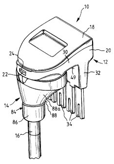
The connector 10 shown in Figures 1 to 4 is designed to mate, in a manner
described later,
with connector module 100, shown in Figures 16 and 17.
Connector 10 has a hollow electrically insulative connector body 12, and a
separately
formed deflector element 14. The deflector element 14 is slidably retained on
an electric
cable 16 which is connected to the connector body 12.
Connector body 12 is formed in two parts, an upper part 18 and a lower part
20. These are
coupled together by three snap fasteners 22, each comprising an aperture 24
and on body
part 18, and a cooperating latching post 26 on body part 20. Posts 26 each
have an
inclined leading cam surface 26a for deflecting the post by camming action
against edges
of the aperture as the posts are passed into the apertures, after which the
cam surfaces pass
through the apertures to allow the posts to return to a substantially
undeflected position at
CA 02493566 2005-01-21
-8-
which release of the two parts 18, 20 is prevented by engagement of transverse
locking
surfaces 26b on the posts 26 with edges of the apertures 24.
The connector body 12 generally defines a first bridging portion 30 having
towards one
end a downwardly depending portion 32 from which project contact portions 34
of
connector 10. As best shown in Figure 4, towards the end of the first portion
30 opposite
portion 32, body 12 has a cable receiving portion 36 (Figure 4) which is
formed on lower
body part 20 and which receives an end portion of cable 16 so that the cable
extends into
the interior of the connector body. Cable receiving portion 36 is in the form
of a
downwardly projecting spigot having a generally cylindrical passageway 38
therethrough
(Figure 18).
The lower body part 20 defines the depending portion 32, a lower part of the
first portion
30 as well as the cable receiving portion 36 and the passageway 38. The body
part 18
forms an upper closure for the connector body 12.
At an underside location, on part 18, there is an internal depending spigot 40
which fits
into the upper part of the passageway 38. The cable 16 passes into the
connector 10 at the
underside, through the spigot 40. Insulated wires 70 of the cable 16 extend
out of the
spigot via a side slot 42 in the spigot and into the interior of body 12.
As best shown in Figure 3, the underside of part 18 has, at an end thereof
opposite the
spigot 40, a side-to-side extending socket structure 44. This depends
downwardly from the
underside of the part 18, and is formed as a rectangular wall 46 which defines
therewithin
an elongate rectangular socket 48. In the assembled connector 10, socket 48
extends
internally across the connector body 12 immediately above the depending
portion 32 of the
connector body part 20.
As viewed from the side, connector body 12 has the cable 16 extending from a
first side 49
adjacent one end and the portion 32 extending generally in parallel at the
same side, but
adjacent the opposite end of the body 12. The cable receiving portion 36 also
extends from
CA 02493566 2010-08-09
-9-
side 49 generally parallel to portion 32.
A connector element 50 of generally rectangular planar form has one end
thereof
accommodated within socket 48 and is frictionally retained therein. The
connector
element 50 is shown in more detail in Figures 11 and 12. It is formed as a
printed circuit
board having an insulative substrate 52 of generally rectangular configuration
with
conductive material thereon arranged to form components as next described.
Particularly,
at a first end portion 55 of the substrate which is received in the socket 48,
the substrate
has formed thereon insulation displacement contacts (IDCs) 54, arranged at the
end edge of
of the substrate 52. At the opposite second end portion 57, the substrate 52
is formed with an
array of fingers 56 which extend in spaced parallel relationship.
The IDCs 54 are formed by opposed portions 60 at the end of the substrate 52,
adjacent
pairs of which form separate ones of the IDCs. These portions 60 are in the
form of
outstanding tongues. Each IDC'has an outwardly open slot 58 defined between
the pair of
opposed portions 60 which'form that IDC. This forms a gap between portions 60.
Edge
surfaces of the slots 58 have electrically conductive edge portions 62. These
are formed by
any suitable way, such as used in forming printed circuit boards by
conventional
techniques. By pressing of an individual wire 70 of the cable 16 into an IDC
slot 58, the
insulation 72 surrounding the inner conductor 74 of the wire is cut by the
edges of the IDC
formed by the conductive edge portions 62 such that electrical connection is
made between
the conductive edge portions 62 and the inner conductor 74 (Figures 14 and
15). To
facilitate entry of the wire into the IDCs, the slots 58 have outwardly
tapered entry portions
58a which are wider at the edge of the substrate than at inner ends of the
sloth.
The socket structure 44 is configured to receive the wires 70 so that
electrical connection is
made between these and the IDCs 54, as at the end of the connector element 50
at which
the IDCs are located is positioned in the socket 48 of the socket structure
44. In particular,
the wall 46 has, in portions thereof at opposite sides of the connector
element 50, notches
76 which are arranged at an angle of 45 with respect to the lengthwise
direction of the
socket structure 44. With the connector element 50 removed from the socket,
the wires 70
CA 02493566 2005-01-21
- 10-
are led from the cable 16, after this is passed into the connector 10 via
cable receiving
portion 36, so as to lie across the socket 48. Each wire 70 is thus received
in two opposed
notches 76 in the manner shown most particularly in Figure 15. Pursuant to the
angled
alignment of the notches 76, the wires 70 thus lie at an angle to the
direction of extent of
socket 48. After this, the connector element 50 is placed in position and
pressed
downwardly into the socket 48 so that the IDCs 54 make connection with the
wires 70 in
the manner described above. The wires are then held in electrically conductive
engagement with the insulation displacement contacts 54 by virtue of the
connector
element 50 being frictionally retained within the socket 48.
The fingers 56 of the connector element 50 have bifurcated free ends, each
forming two
spaced prongs 80. The prongs 80 have electrical contacts 82 therein, formed as
conductive
layers on opposite faces of the insulative substrate 52. Circuit tracks 78 on
the printed
circuit board, at either face, interconnect ones of the contacts 82 with ones
of the insulation
displacement contacts 54.
Contacts 82 are disposed two on each prong 80, one on the face of the
substrate 52 shown
in Figure 11, and one on the obverse face. On the substrate 52, however, only
one of each
pair on a single prong 80 is connected to a track 78, in each case being the
contact on the
face shown in Figure 11. The conductive tracks 78 are partly formed on the
face of the
substrate 52 shown in Figure 11 and partly on the face. Parts of the tracks on
the obverse
face are shown in broken lines. Connections between parts of the tracks at
either side are
made by annular conductive portions 81 on the surfaces of through holes
through the
substrate. The arrangement results in crossings of tracks 78, between adjacent
pairs
thereof. This may assist in reduction of crosstalk in signals passing on the
tracks 78.
In the assembled connector 10, the connector element 50 extends downwardly
within
connector body 12 from socket structure 44 into downwardly depending portion
32 of
body 12 so that the fingers 56 project downwardly through openings 95 in a
lower end wall
97 of body portion 32 (Figures 13 and 18). The so projecting portions of the
fingers 56
form the contact portions 34 of connector 10.
CA 02493566 2005-01-21
-ll-
As best shown in Figure 18, the connector element 50 is retained in position
by
engagement at end portion 55 by the socket structure 44 and by engagement of
inward
steps 52a on substrate 52 with ledges 93 formed on the internal side walls of
the connector
body 12. By this arrangement, assembly of the connector 10 is relatively
simple. For
example, cable 16 may first be passed through deflector element 14, thence
through
passageway 38 in cable receiving portion 36 of body part 20, and into spigot
40. End
portions of wires 70 from the cable 16 may then be laid into the notches 76 on
socket
structure 44, as shown in Figure 3, Then, the connector element 50 may be
assembled to
the socket structure and upper body part 18. After that, assembly may be
completed by
passing the fingers 56 through the openings 95 of body part 20, and the body
parts 18, 20
snapped together by pressing towards each other such as to engage the snap
fasteners 22.
The assembly may be performed with the upper wall portion 99 of body part 18
(Figure
13) facing downwards as shown in Figure 3.
The deflector element 14 has a body 84 formed for example of plastics
material. At one
end, it has an entry portion 86 with a central passageway 94 therethrough, by
which the
cable 16 extends through the deflector element 14. From the portion 86, the
body 84
extends upwardly as viewed in Figures 1 and 4 at an outwardly and upwardly
divergent
hollow portion 88. Portion 88 is of a somewhat conical form, but flat at one
side.
Referring to Figure 18, the passageway 94 is arranged to frictionally grip the
cable 16 so
that the deflector element 14 may be moved lengthwise on the cable, but still
maintain a
set position along the length of the cable due to frictional engagement
therewith. In a
position where the deflector element 14 is moved on the cable 16 so as to be
close to the
connector body 12, and the deflector element 14 is appropriately rotated on
cable 16
(Figures 1 and 18) the cable receiving portion 36 is received in an enlarged
upper end of
passageway 94. In this condition, the portion 88 of the deflector element 14
encompasses
the underside of the connector body 12 and a generally planar side surface 98
of the body
84 is in spaced parallel relationship to an inner planar surface 28 of body
portion 32. The
deflector element can however be moved away from this position downwardly on
the cable
CA 02493566 2005-01-21
- 12-
as viewed in Figure 1, and thence sidewardly, to the right as viewed in Figure
1, under
bending of the cable 16, so to pass below the lower end of the contact
portions 34. It can
then be moved upwardly to the position shown in Figure 4 so that the contact
portions 34
of the connector 10 are captured in upwardly open pockets 92 formed adjacent
but inside
the side surface 98 of the deflector element 14. By this, the portion 88
presents a sloping,
somewhat conical deflector surface 88a around the contact portions 34.
With the element 14 positioned as shown in Figure 4, the cable 16 may be used
to pull the
connector 10 through a space having numerous electrical wires without the
connector
being caught by the wires. As described, the portion 88 presents a smooth
conical
deflector surface 88a and, by this, as the cable and connector are so pulled
through, wiring
to either side of the connector 10 is either laterally pushed outwardly by
camming action
against surface 88a of the deflector element 14 or else, by similar camming
action, the
connector 10 itself and deflector element 14 are so moved sidewardly to enable
the
connector 10 and deflector element 14 to pass easily. It will be appreciated
that, because
the connector 10 and attached cable 16 otherwise, present a somewhat U-shaped
configuration from one leg of which extends the cable 16, the connector may
otherwise be
easily fouled on surrounding wiring by being captured between the portion 32,
or
projecting contact portions 34, and the cable 16 or cable receiving portion
36. The
deflector element 14 effectively bridges portion 32 and the cable and cable
receiving
portion 36.
Referring particularly to Figures 16 and 17, the connector 10 is used to make
connections
to the module 100 by positioning it so that the portion 30 and projecting
contact portions
34 extend to a central lengthwise extending trough 104 of the connector
module, with the
portion 30 extending sidewardly from the trough over the top of the module at
one side,
and with the cable 16 and deflector element 14 positioned adjacent an outer
upright surface
106 of the module.
The trough 104 is defined between two opposed rows of upstanding posts 108
extending
lengthwise along the upper part of the module. Between adjacent pairs of these
are
CA 02493566 2005-01-21
-13-
positioned insulation displacement contacts 112 (Figure 17). These enable
external
connections to be made to the module by positioning wires (not shown) in
these. The
IDCs 112 are formed as parts of respective single contact members 120 which
have, at
locations underneath the trough 104, upstanding spring contact portions 114.
Opposed
associated IDCs 112 in each of the rows of these have contact portions 114 in
adjacent
relationship immediately below the trough 104. The associated pairs of the
contact
portions 114 may, for example, be normally engaged so as to interconnect
associated
contact members 120 across the rows or may be normally disconnected that is,
not
touching each other so as to isolate the associated contact members 120. In
any event, the
trough 104 has, in a lower portion thereof, openings 122 into which the
contact portions 34
project when the connector 10 is positioned on the module 100 in the manner
shown in
Figures 16 and 17. The upper ends of the contact portions 114 are positioned
so that these
are displaced outwardly as a contact portion 34 enters between them, and such
that they
interconnect with respective ones of the contacts 82 of contact portions 34,
across the
module. Accordingly, when the connector 10 is so assembled onto the module
100,
electrical connections are made from wires 70 of the cable 16 via the
connector contact
portions 34 to the contact members 120 of the module, via the contacts 82 and
contact
portions 114.
Figures 5 to 10 illustrate an alternative form of deflector element 140 formed
in
accordance with the invention. In these Figures, like reference numerals
denote like parts
in Figures 1 to 4 and 11 to 18 and the following description is confined to
differences
between the deflector elements 14 and 140. In particular, the body 142 of the
deflector
element 140 has an extended generally flat portion 144 at one side, the other
side being
generally part-conical with an outer surface similar to surface 88a of the
deflector element
14 (Figures 1 and 4). Portion 144 has, at its inner side, pockets 92 for
receiving the contact
portions 34. Portion 144 is positioned immediately outside the contact
portions 34 of
connector 10, when the deflector element is positioned for use in pulling
through. In this
configuration, an outer generally flat surface 146 on portion 144 lies
substantially flush
with an adjacent generally planar surface 150 (Figure 5) of connector body 12,
and the
fingers 56 of the connector element 50 are, as in the case of the deflector
element 14,
CA 02493566 2005-01-21
- 14-
received in pockets 92. Figure 10 illustrates the manner in which fingers 56
of the
connector element 50 fit into the pockets 92. In this figure, the connector
element 50 is
shown by phantom lines in the pockets 92. The deflector element 140 can,
however, be
moved to the position shown in Figure 6, where generally flat portion 144, and
surface
146, are in spaced generally parallel relationship to portion 34 of connector
body 12.
Embodiments of the invention are useful as patch cord connectors, where the
cable 16 is in
the form of a patch cord. The patch cord may have connectors 10 at each end,
for
example.
Throughout this specification and the claims which follow, unless the context
requires
otherwise, the word "comprise", and variations such as "comprises" and
"comprising", will
be understood to imply the inclusion of a stated integer or step or group of
integers or steps
but not the exclusion of any other integer or step or group of integers or
steps.
The reference to any prior art in this specification is not, and should not be
taken as, an
acknowledgment or any form of suggestion that that prior art forms part of the
common
general knowledge in Australia.
The reference numerals in the claims are provided for ease of reference to the
drawings
and are not to be taken as limiting the claims to constructions where integers
are identified
by such reference numerals in the claims are necessarily limited to being
formed as shown
or described with reference to the drawings.
CA 02493566 2005-01-21
- 15-
LIST OF COMPONENTS:
Electrical Connector
5 12 Body (connector 10)
14 Deflector element
16 Electric cable
18 Upper part (of connector body 12)
Lower part (of connector body 12)
15 22 Snap fasteners with apertures and co-operating posts
24 Apertures (of snap fasteners 22)
26 Latching posts (of snap fasteners 22)
26a Cam surfaces (on latching posts 26)
26b Locking surfaces (on posts 24)
28 Inner planar surface (of portion 32 of connector body 12)
First bridging portion (of connector body 12)
32 Downwardly depending portion (of connector body 12)
34 Contact portions (of connector 10).
36 Cable receiving portion (of connector body 12)
38 Passageway (through cable receiving portion 36).
Spigot 40
42 Slot (in spigot 40)
44 Socket structure (on part 18)
46 Rectangular wall (of socket structure 44)
48 Socket (of socket structure 44)
CA 02493566 2005-01-21
-16-
49 Side (of connector 10)
50 Connector element
52 Insulative substrate (of connector element 50)
52a Inward steps (on substrate 52)
54 Insulation displacement contacts (of connector element 50)
55 First end portion (of connector element 50)
56 Fingers (on substrate 52)
57 Second end portion (of connector element 50)
58 Slots 58 (of insulation displacement contacts 54)
58a Entry portion (of slot 58)
60 Opposed portions (of IDCs 54 on connector element 50)
62 Conductive edge portions (on slots 58)
70 Insulated wires
72 Insulation (of wires 70)
74 Conductors (of wires 70)
76 Notches
78 Circuit tracks (on substrate 52)
80 Prongs
81 Annular conductive portions
82 Contacts
84 Body (of deflector element 14)
86 Entry portion (of body 84)
88 Upwardly divergent hollow portion (of body 84)
CA 02493566 2005-01-21
-17-
88a Deflector surface
92 Pockets (in deflector element 14)
93 Ledges (on inner side surfaces of casing part 20)
94 Central passageway (of deflector element 14)
95 Openings (in body portion 32)
97 Wall (of depending portion 32)
98 Planar side surface
99 Upper wall (of connector body part 12)
100 Connector module
104 Trough (module 100)
106 Side surface (module 100)
108 Upstanding posts (module 100)
112 IDCs
114 Contact portions
120 Contact members
122 Openings (in module 100)
140 Deflector element
142 Body (of deflector element 140)
144 Generally flat portion (of deflector element 140)
146 Outer generally flat surface (of portion 144)
150 Surface (on connector body 12)