Note: Descriptions are shown in the official language in which they were submitted.
CA 02493742 2005-O1-26
WO 2004/012374 PCT/US2003/022728
METHOD AND APPARATUS FOR WLAN-UMTS
INTERWORKING EMPLOYING UMTS AIR INTERFACE
FIELD OF INVENTION
The present invention relates to wireless communications. More
particularly the invention deals with WLAN-UMTS interworking.
BACKGROUND
Subscribers, such as mobile stations (UEs), to a universal mobile
telecommunication system (UNITS) which are operating under a wireless local
area network (WLAN) environment and desire to access the UMTS, can incur
a significant increase in costs when accessing UMTSs in those areas where the
UMTS system access would be of substantial cost.
[0006] The present invention provides a less expensive alternative for
accessing a UMTS without incurring such substantial costs. The composite
systems of the present invention comprises a UMTS system underlayed by a
WLAN system. The UMTS is provided with a transceiver acting as a UMTS
radio front-end for a UMTS subscriber operating in a WLAN environment.
The interface between the UMTS system and the end user (UE) is obtained
through the WLAN interface.
[0007] The WLAN system converts received UMTS messages and/or
traffic for pre-registered users into a format suitable for WLAN transmission
to be delivered to users operating in WLAN environments. In addition, the
WLAN converts transmitted messages and traffic flows into UMTS formats
which is then transmitted to the UMTS system by way of the UMTS
transceiver supporting the WLAN system. The WLAN users gain access to
the UMTS system through a UMTS air interface employing a translator.
BRIEF DESCRIPTION OF THE FIGURES
The present invention will be understood from a consideration of
the accompanying description and drawings in which like elements are
-1-
CA 02493742 2005-O1-26
WO 2004/012374 PCT/US2003/022728
designated by like numerals and, wherein:
Figure 1 is a diagram of a UMTS system underlayed by a WLAN
system.
Figures 2 and 3 are diagrams showing the message utilized for
the WLAN-UMTS interworking in accordance with the apparatus and
methods of the present invention.
DETAILED DESCRIPTION OF THE PREFERRED EMBODIMENTS
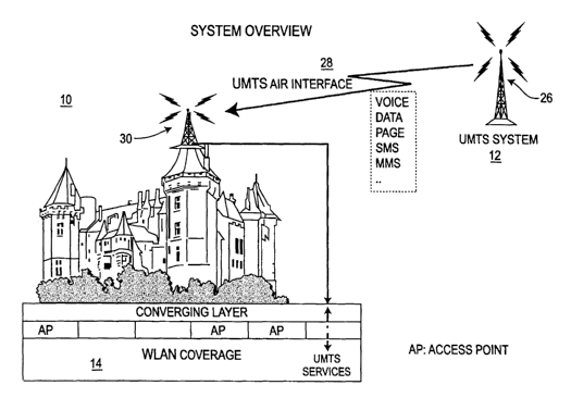
Figure 1 shows an arrangement 10 useful in explaining the
interworking between a UMTS system 12 and WLAN system 14. The
arrangement of Figure 1 will be described in conjunction with the technique
for delivery of UMTS based services when a mobile station such as a remote
terminal is served by the WLAN system.
[0014] Making reference to Figure 2, and, where appropriate, Figure 1,
there is shown an arrangement similar to that of Fig. 1.
[0015] Only one mobile station 24 is shown for purposes of simplicity, it
being understood that a plurality of such mobile terminals are serviced by the
WLAN 14. Although the mobile station remote terminal (UE) 24 may also be
a dual-mode terminal capable of communicating with a WLAN and a UMTS,
for purposes the present invention, a WLAN-capable terminal 24 is utilized.
[0016] User terminal (UE) 24, through its WLAN capability 24A,
registers with WLAN 14, at step S1. WLAN 14, at step S2, then registers the
user identification (ID) for the UMTS service watch, communicating with
UMTS transceiver 18. UMTS transceiver 18 is tuned for any services
addressed to registered users' identifications (IDs). When a UMTS service,
such as a page, short message service (SMS), multimedia message service
(MMS) or the like is to be delivered, UMTS 12 transfers such a service, in the
example given a page message, at step S3, the page message being delivered
to UMTS transceiver 18. UMTS transceiver 18, a step S4, typically from a
radio tower 26, transmits the page message over UMTS air interface 28 to a
-2-
CA 02493742 2005-O1-26
WO 2004/012374 PCT/US2003/022728
receiving radio tower 30, to format converter 16 which, at step S5, converts
the present (UMTS) format into a WLAN message format and, at step S6,
communicates the page message, in WLAN message format, to WLAN 14.
WLAN 14, at step S7, delivers the page message to mobile terminal 24. An
acknowledgement is relayed from terminal 24, at step S8, to WLAN 14, the
acknowledgement being transferred to format converter 16 at step S9 and
from there to UMTS transceiver 18, at step 510, and finally to UMTS 12, at
step 511.
Figure 3 shows a terminal 24 similar to that shown in Fig. 2,
which, through its WLAN capability 24A, registers with WLAN 14, at step S1.
The WLAN 14, at step S2, forwards the user registration to format converter
16 which, at step S3, changes the format into a UMTS message format and, at
step S4, provides a UMTS package switched (PS) UMTS attachment directed
to the UMTS transceiver 18. UMTS transceiver 18 transfers the UMTS PS
attached to UMTS 12, at step S5.
The PS attach completed message is transferred from UMTS 12
to UMTS transceiver 18, at step S6, and from UMTS transceiver 18 to format
converter 16, at step S7. Format converter 16, at step S8, changes the format
of the PS attach into a WLAN message format and, at step S9, conveys the
message to WLAN 14 which, at step 510, provides the message to mobile
terminal 24. Acknowledgement from terminal 24 to WLAN 14 occurs at step
511, from WLAN 14 to format converter 16, at step 512, from format converter
16 to UMTS transceiver 18, at step S13 and the UMTS transceiver 18 to
UMTS 12, at step 514, thereby completing the acknowledgment.
* *
-3-